
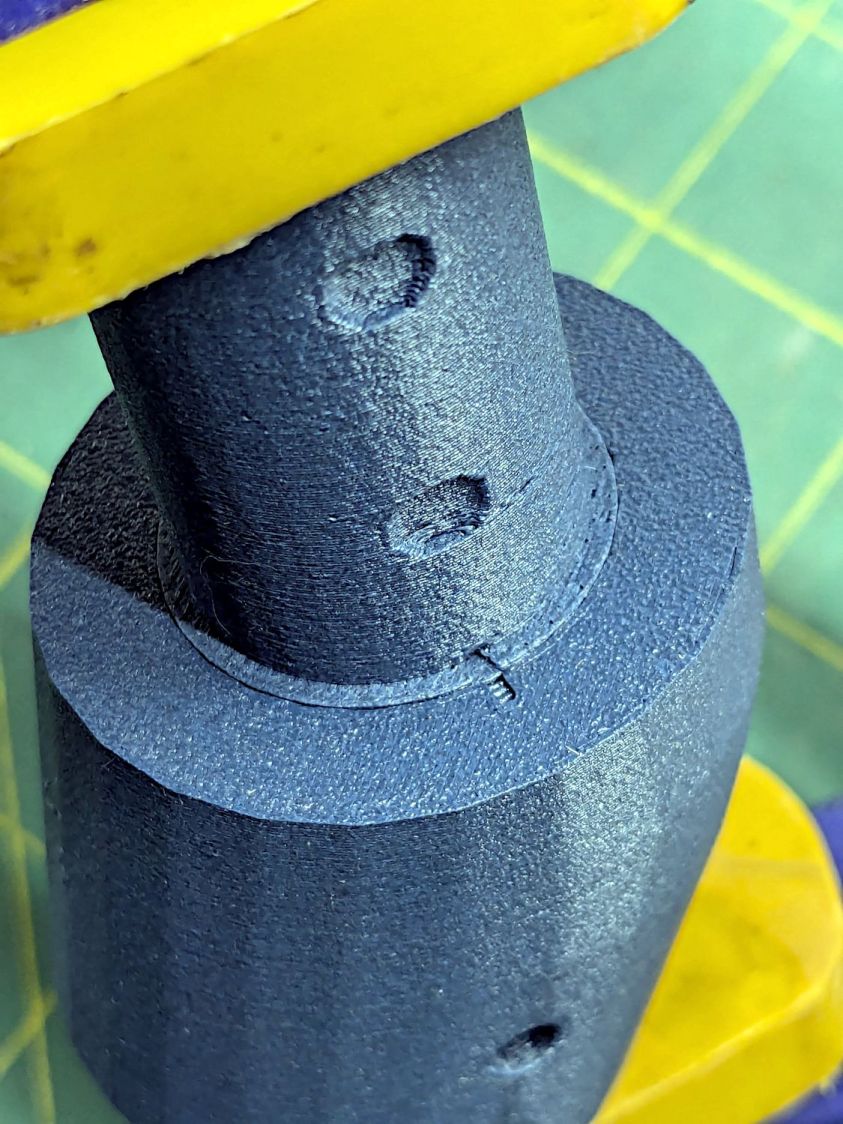
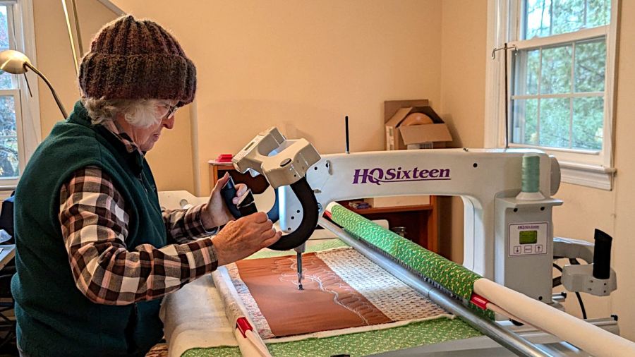
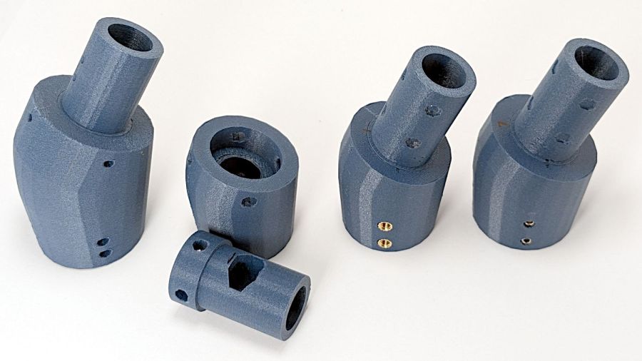
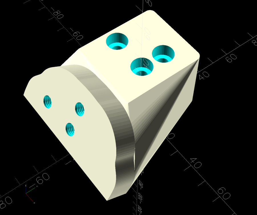
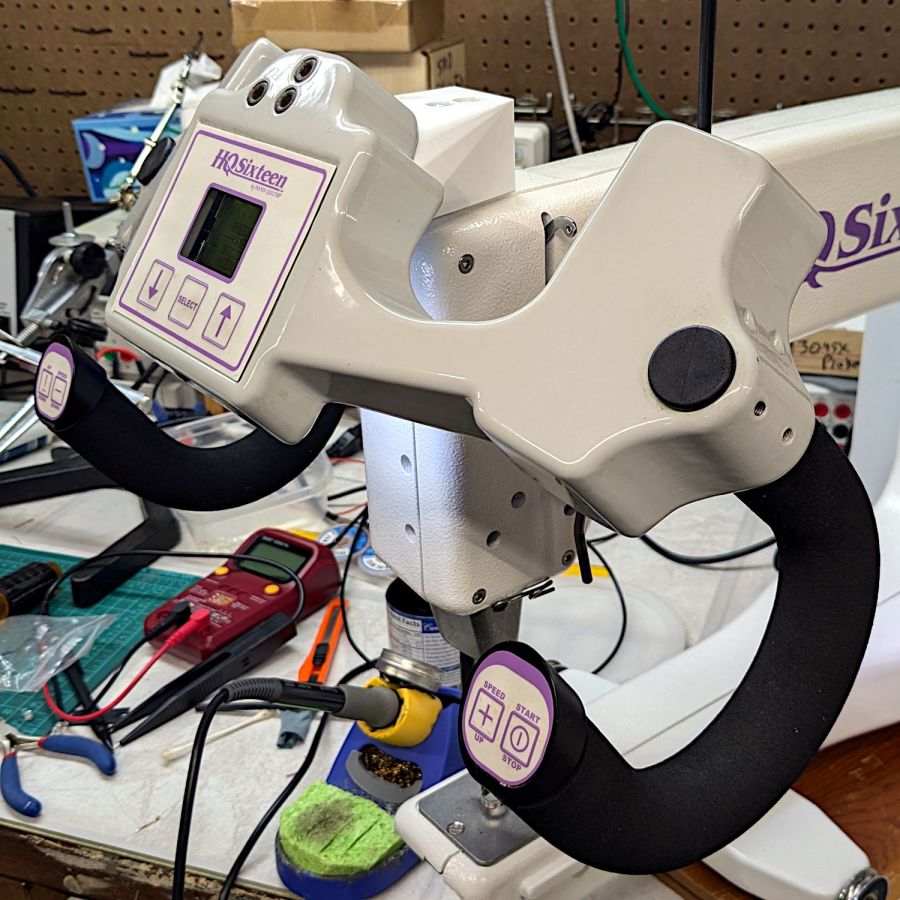
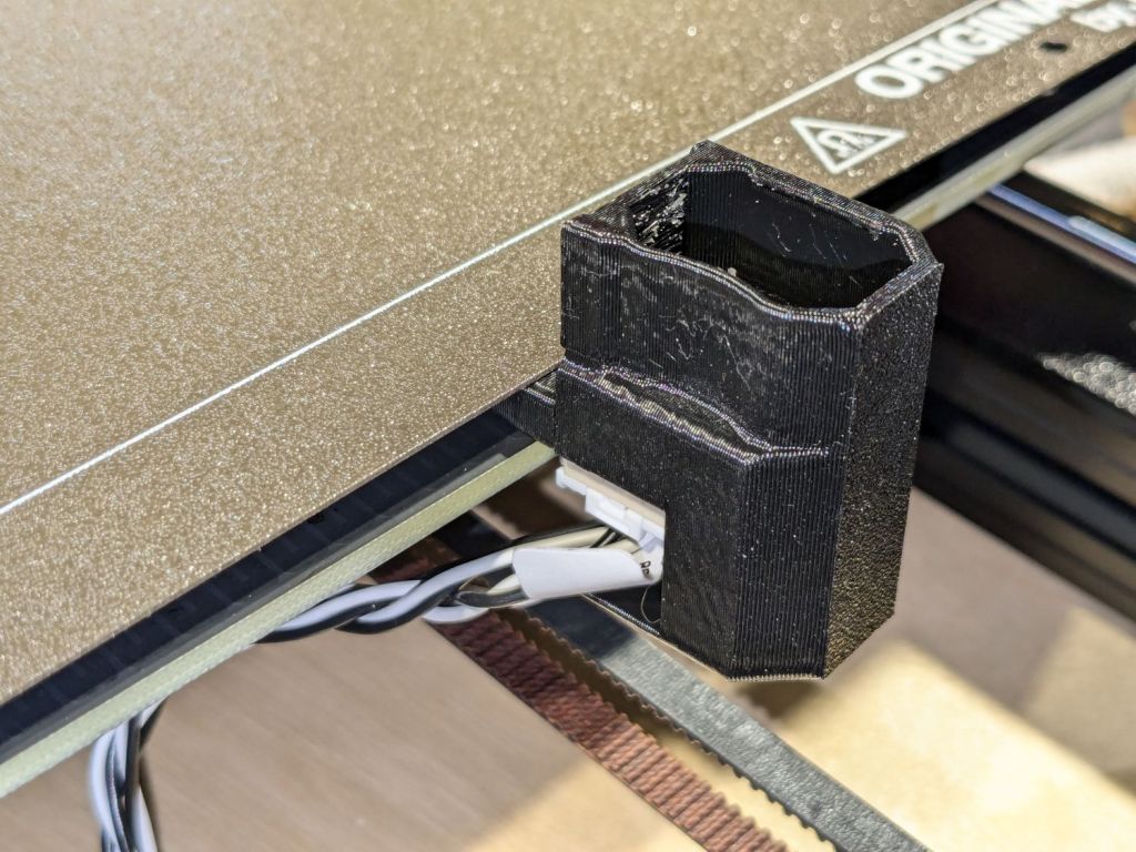
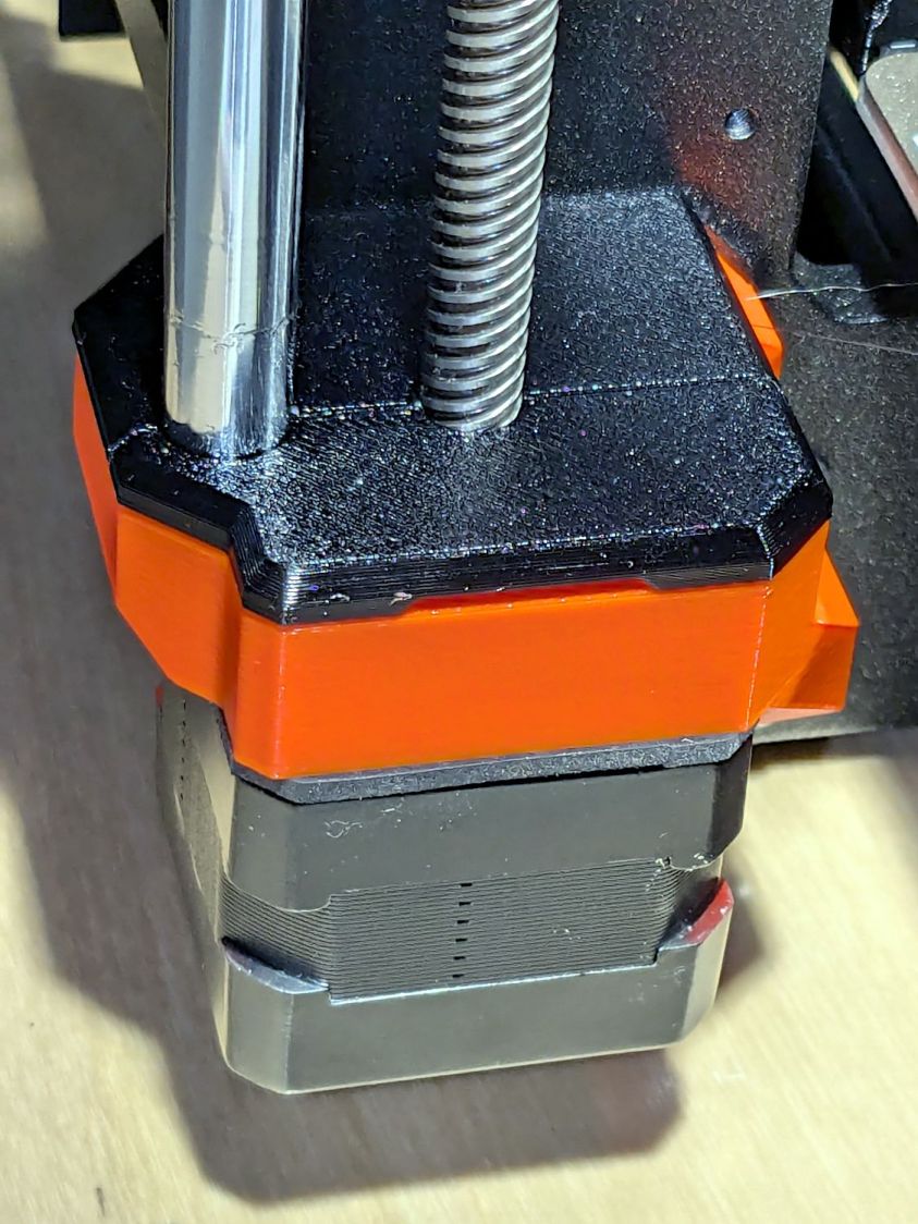
The grip plug is the upper part of the assembly changing the angle of the HQ Sixteen’s front grips:
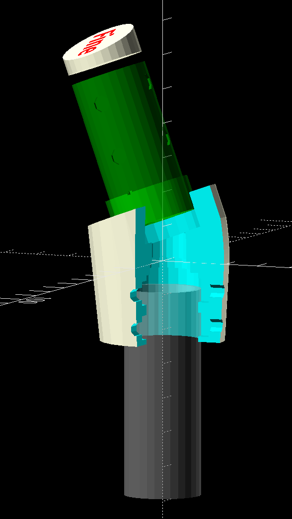
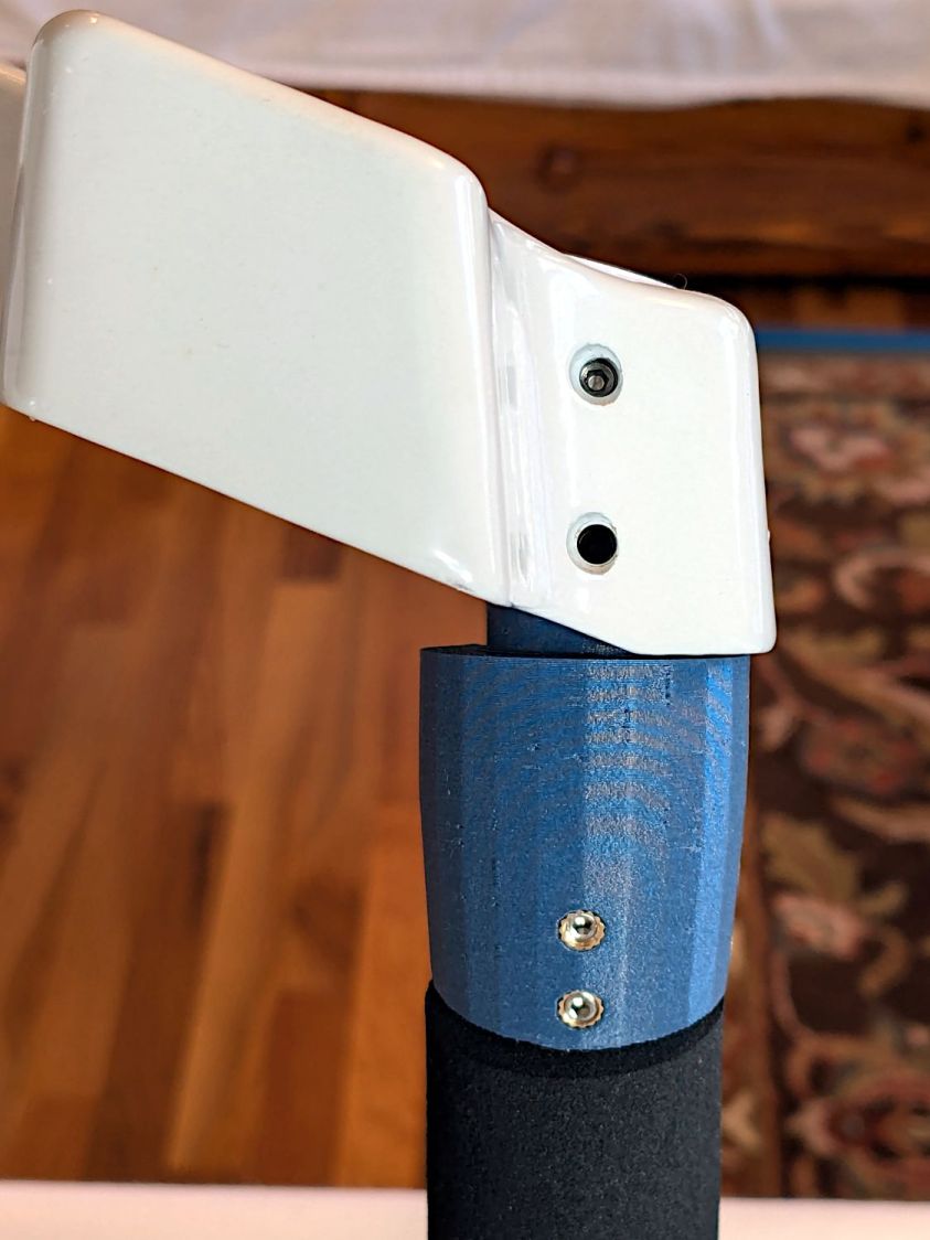
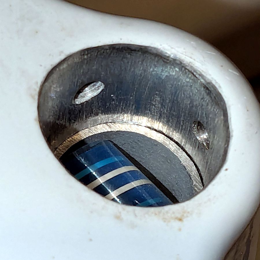
It sticks into the machine’s handlebar control base in place of the original aluminum tube grips:
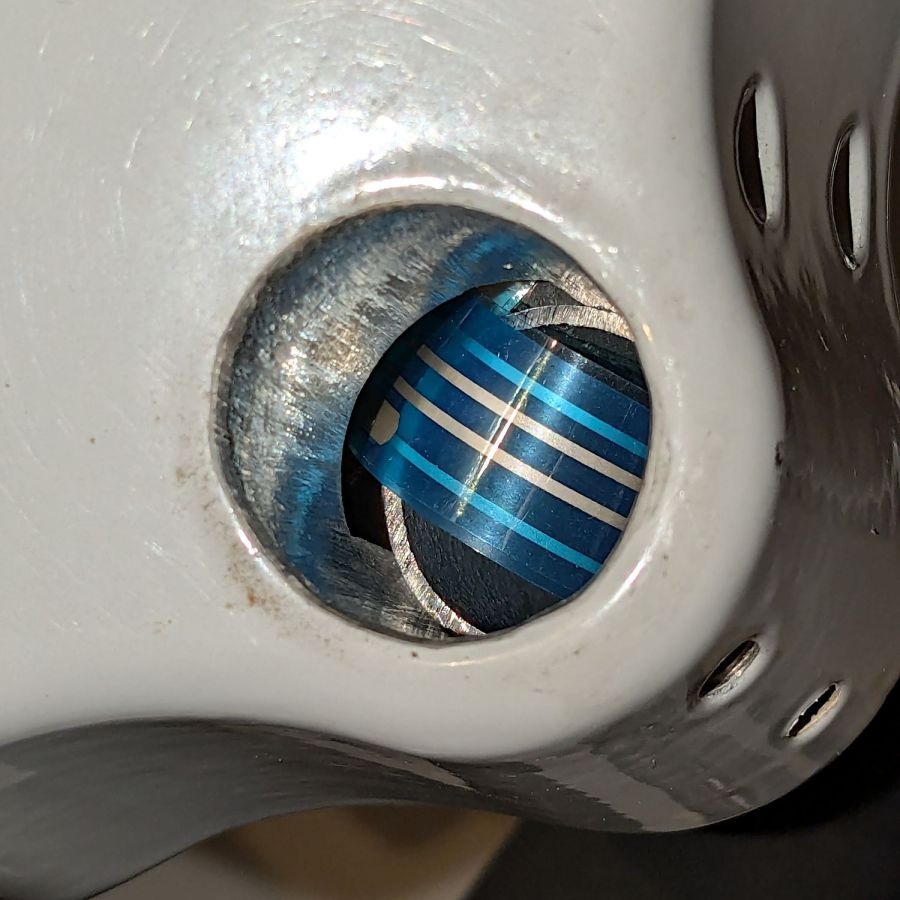
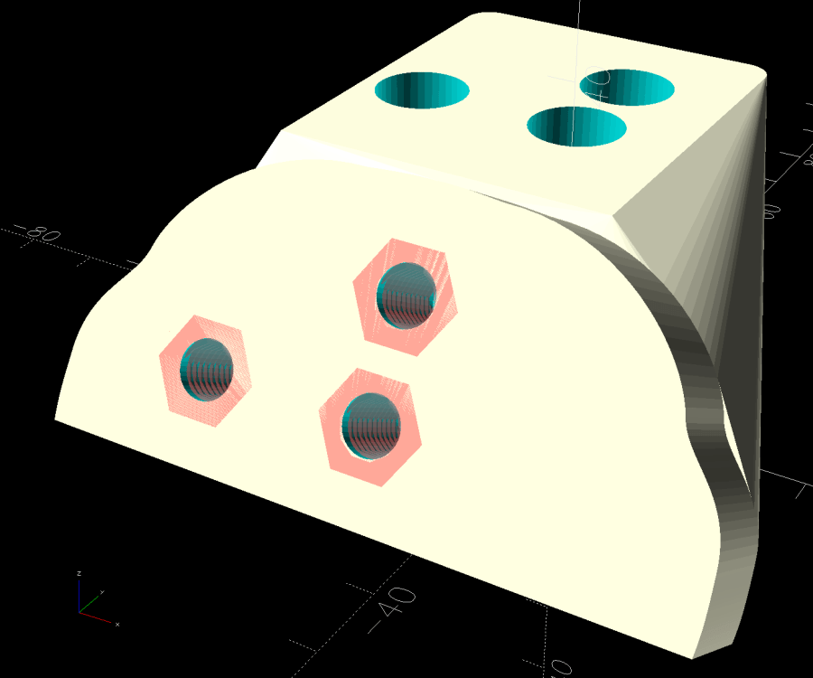
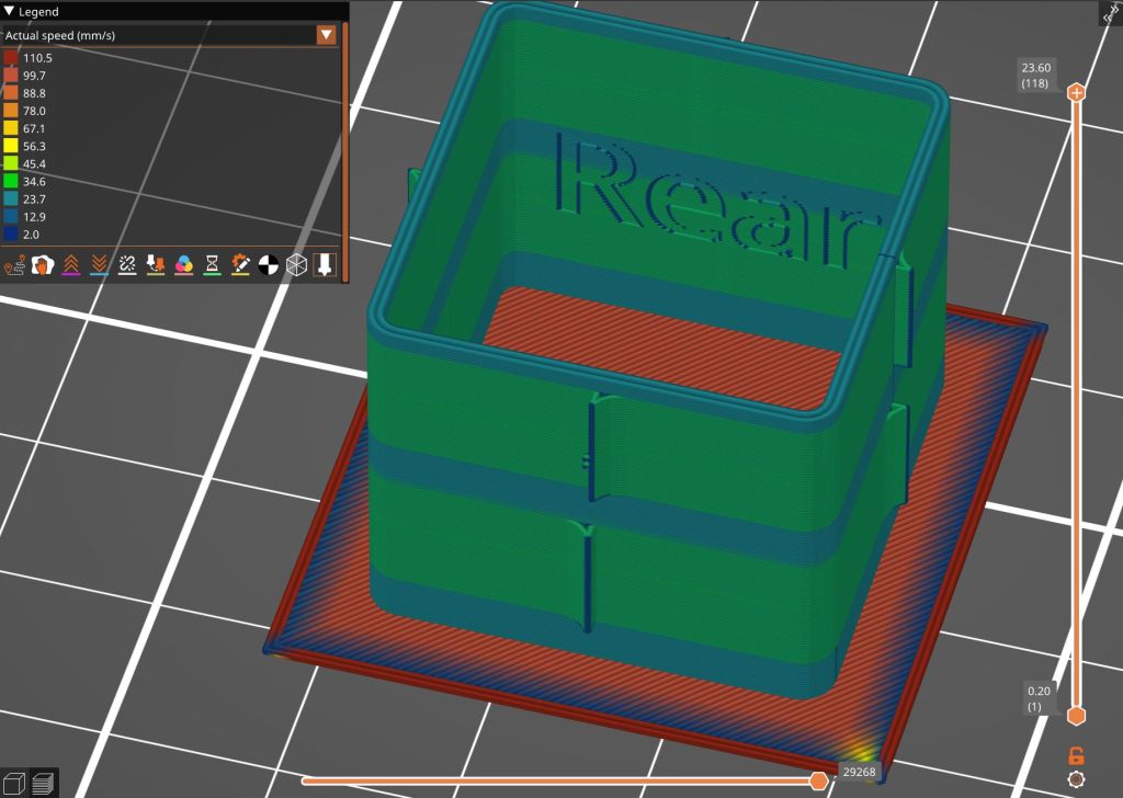
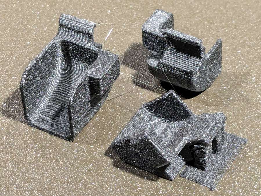
Only the two lower setscrews held the original grip in place, but I made the plug tall enough to engage all four, which meant it needed a side port to ease the ribbon cable through on its way to the PCB inside:
The plastic tube is obviously thicker than the aluminum tube, with four dents capturing the 10-32 setscrews (using a 3/32 inch wrench) to align it within the hole; the bore juuust passes the original connector.
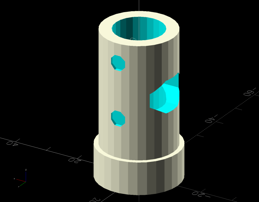
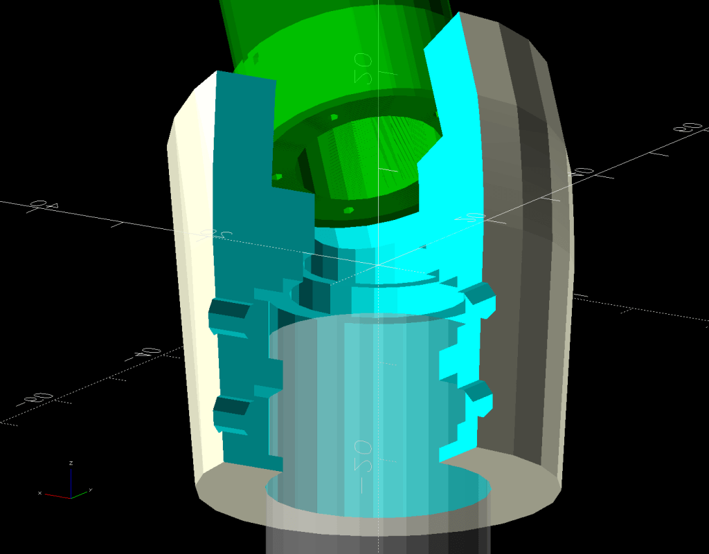
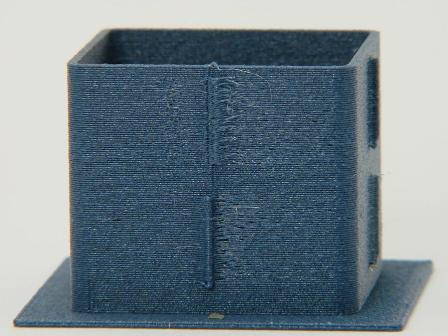
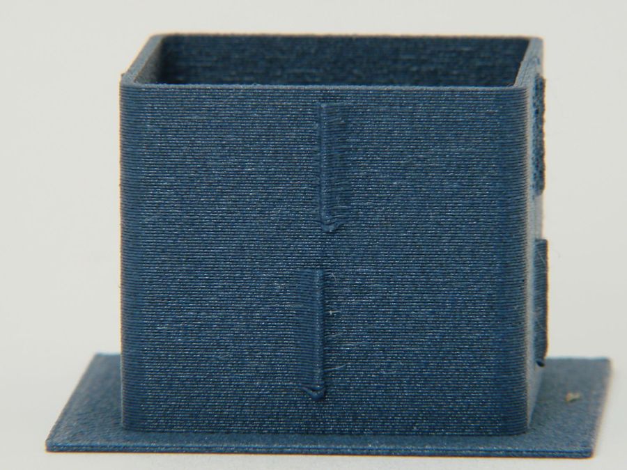
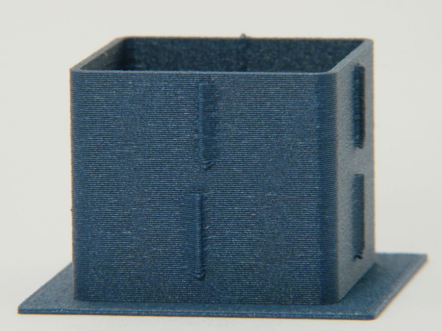
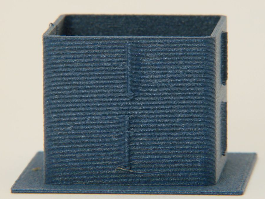
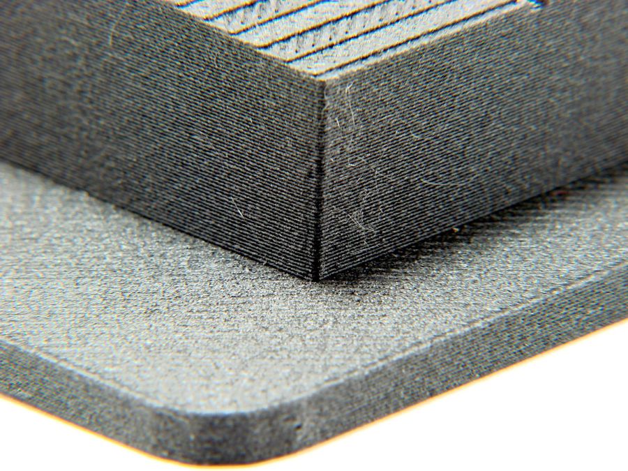
The plug glues into the angle block, which means all the stress from the grips passes through a thin ring of plastic just above the joint. So I added five 1.2 mm OD hard steel wires about 20 mm long:
Five wires, because four didn’t seem like quite enough and six seemed like crowding too much steel into too little plastic. The holes are offset to avoid the setscrew dents, with one lined up directly under the cable port.
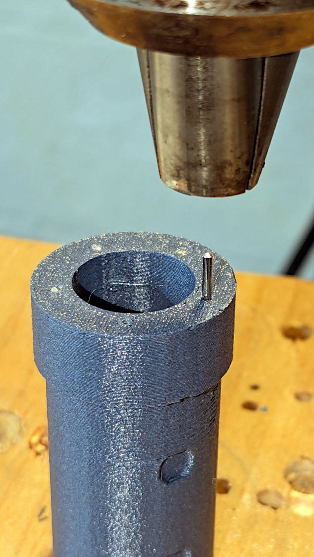
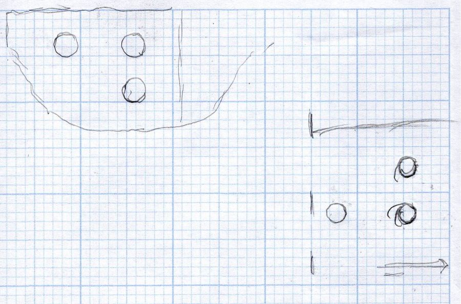
A pair of alignment marks help get the orientation right while gluing:
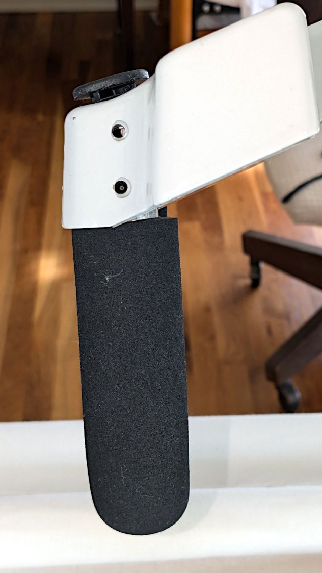
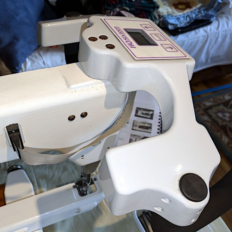
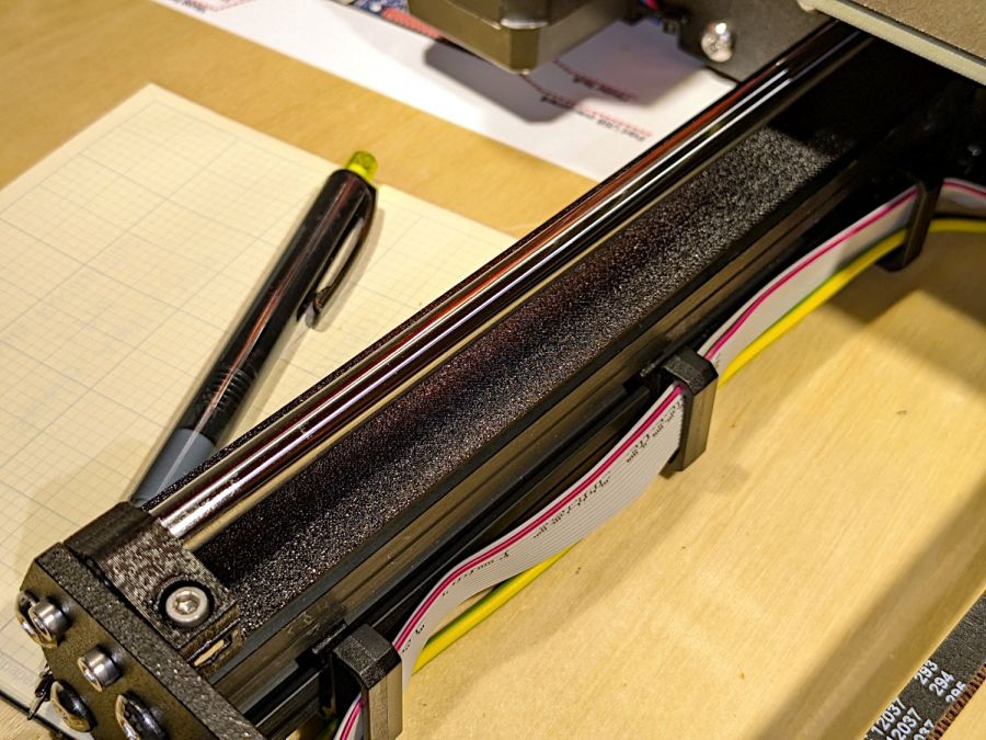
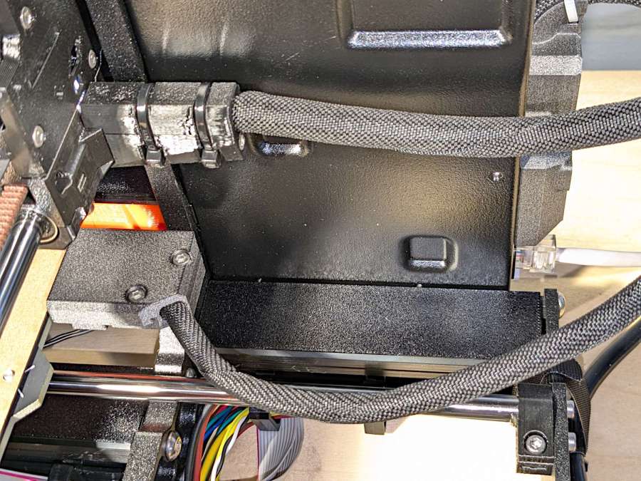
The control base angles away from the grip, leaving a little more than half unsupported:
Pondering that picture suggested adding those steel wires.
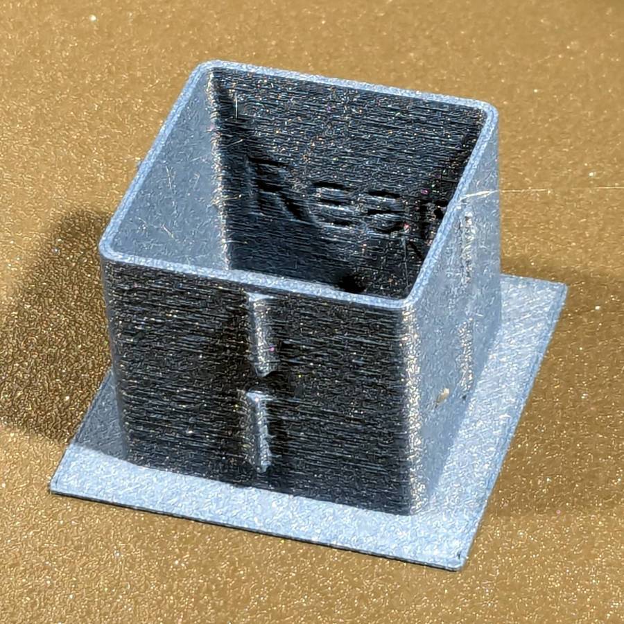
The angle block prints with its upper surface against the MK4’s platform to get good dimensions inside the recess for the plug, so I can’t add a wedge to that surface, nor can it go on the plug. Maybe a separate wedge glued around the plug?
However, the pin header for that cable sits directly inside the base and a transparent cover (not shown here) extends outward over the casting against the grip:
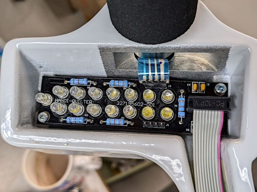
So maybe it’s like that and that’s the way it is.
The OpenSCAD source code as a GitHub Gist:
| // Handiquilter HQ Sixteen front handlebar grip angle mount | |
| // Ed Nisley – KE4ZNU | |
| // 2024-11-29 | |
| include <BOSL2/std.scad> | |
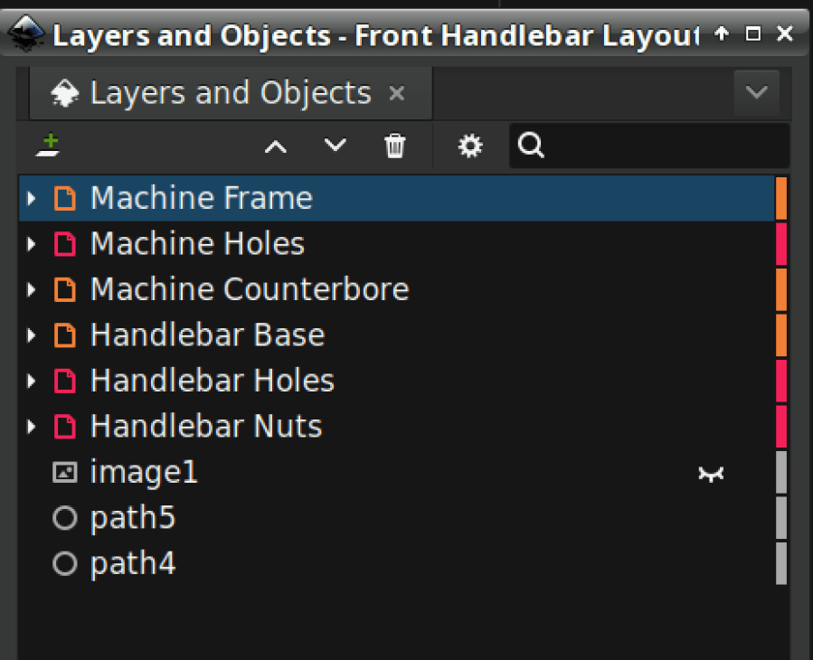
| Layout = "Show"; // [Show,Build,Plug,Block,Covers,Cover] | |
| Material = "All"; // [All,Cover,Text] | |
| // Angle w.r.t. base | |
| GripAngle = 20; // [10:30] | |
| // Plug glued, not screwed | |
| PlugGlue = true; | |
| // Square nuts, not inserts | |
| SquareNuts = true; | |
| // Additional length of bottom | |
| AddLength = 0; // [0:20] | |
| // Separation in Show display | |
| Gap = 5; // [0:20] | |
| /* [Hidden] */ | |
| HoleWindage = 0.1; | |
| Protrusion = 0.1; | |
| NumSides = 2*3*4; | |
| ID = 0; | |
| OD = 1; | |
| LENGTH = 2; | |
| Grip = [19.7,22.4,20.0]; // (7/8)*INCH = 22.2 mm + roughness, LENGTH=OEM insertion depth | |
| GripRadius = Grip[OD]/2; // used everywhere | |
| Plug = [15.0,Grip[OD],45.0]; // inserts into handlebar base | |
| PlugRim = [Plug[ID],25.0,10.0]; // … sits against handlebar base | |
| BaseScrewPositions = [[11.0,12.0],[27.0,29.0]]; // setscrew offsets from rim top: side,rear | |
| BaseCutout = [Plug[OD]/2,Plug[ID],10]; // cable cutout into base | |
| BaseCutoutOffset = 18.0; // … centerline position w.r.t. rim | |
| WallThick = 7.0; // should at least fit insert length | |
| SupportSag = 0.4; // vertical sag over support structure | |
| MidLength = AddLength + 3.0; // total length allowing for grip tube stop | |
| TopOD = PlugRim[OD] + 2*WallThick; | |
| BotOD = Grip[OD] + 2*WallThick; | |
| BaseScrew = [4.0,4.8 + HoleWindage,1.0]; // HQ 10-32 screws, LENGTH=capture dent | |
| Insert = [5.4,6.0,6.0]; // M4 inserts in plug rim | |
| //Insert = [4.0,5.0,5.0]; // M4 inserts in plug rim | |
| Screw = [3.5,4.0,1]; // M4 screws through angle block to inserts | |
| ScrewHeadOD = 7.4 + 0.4; // M4 BHCS head + comfort | |
| SquareNut = [4.0,7.0,3.0 + 0.4]; // M4 square nut LENGTH + inset allowance | |
| NutInset = GripRadius – sqrt(pow(GripRadius,2) – pow(SquareNut[OD],2)/4); | |
| PinOD = 1.2; // plug reinforcing pins | |
| NumPins = 5; | |
| CoverThick = [3.5,9.5]; // low and high sides of grip covers | |
| CoverAngle = atan((CoverThick[1] – CoverThick[0])/Plug[OD]); | |
| LogoText = ["Sew","Fine"]; | |
| LogoFont = "Fira Sans Condensed:style=SemiBold"; | |
| LogoSize = 7.5; | |
| LogoColor = "Red"; | |
| LogoThick = 0.8; | |
| //———- | |
| // Simulator for aluminum plug replacing handlebar in base | |
| module BasePlug() { | |
| difference() { | |
| union() { | |
| tube(Plug[LENGTH],(Plug[OD] – HoleWindage)/2,Plug[ID]/2,anchor=DOWN); | |
| tube(PlugRim[LENGTH],PlugRim[OD]/2,PlugRim[ID]/2,anchor=DOWN); | |
| } | |
| up(BaseCutoutOffset + PlugRim[LENGTH]) | |
| left(Plug[OD]/4) | |
| resize(BaseCutout) | |
| yrot(90) zrot(180/8) | |
| cylinder(d=1,h=1,$fn=8,center=true); | |
| up(PlugRim[LENGTH]) | |
| right(PlugRim[OD]/2 – 1.0) | |
| cube([2.0,1.0,1.0],center=true); | |
| for (i = [0:NumPins – 1]) | |
| zrot(i*360/NumPins + 180/NumPins) | |
| down(Protrusion) | |
| right((Plug[OD] + Plug[ID])/4) | |
| zrot(180/6) | |
| cylinder(d=PinOD,h=2*PlugRim[LENGTH],$fn=6); | |
| for (k = [0:1]) // recesses in plug to capture base setscrews | |
| for (a = [0:1]) | |
| up(PlugRim[LENGTH] + BaseScrewPositions[k][a]) | |
| zrot(a*90) | |
| right(Plug[OD]/2) | |
| yrot(90) zrot(180/8) | |
| cylinder(d=BaseScrew[OD],h=2*BaseScrew[LENGTH],$fn=8,center=true); | |
| if (!PlugGlue) | |
| for (a = [0:1]) // inserts for angle block screws | |
| up(PlugRim[LENGTH]/2) | |
| zrot(a*90) | |
| yrot(90) zrot(180/8) | |
| cylinder(d=Insert[OD],h=2*PlugRim[OD],$fn=8,center=true); | |
| } | |
| } | |
| //———- | |
| // Block fitting against handlebar base with handlebar angle | |
| module AngleBlock() { | |
| difference() { | |
| hull() { | |
| up((TopOD/2)*sin(GripAngle)) | |
| xrot(GripAngle) | |
| cylinder(d=TopOD,h=PlugRim[LENGTH],$fn=NumSides); | |
| for (a = [1:2:GripAngle+1]) | |
| up((TopOD/2)*sin(a-1)) | |
| hull() { | |
| xrot(a) | |
| cylinder(d=TopOD,h=0.1,$fn=NumSides); | |
| xrot(a-1) | |
| cylinder(d=TopOD,h=0.1,$fn=NumSides); | |
| } | |
| down(Grip[LENGTH] + MidLength) | |
| cylinder(d=(Grip[OD] + 2*WallThick),h=0.1,$fn=NumSides); | |
| } | |
| up((TopOD/2)*sin(GripAngle)) | |
| xrot(GripAngle) | |
| down(SupportSag) | |
| cylinder(d=(PlugRim[OD] + HoleWindage), | |
| h=PlugRim[LENGTH] + SupportSag + Protrusion, | |
| $fn=NumSides); | |
| up((TopOD/2)*sin(GripAngle)) | |
| sphere(d=PlugRim[ID],$fn=NumSides); | |
| cylinder(d=PlugRim[ID],h=(TopOD/2)*sin(GripAngle),$fn=NumSides); | |
| down(MidLength + Protrusion) | |
| cylinder(d=(Grip[ID] – 2.0),h=(MidLength + 2*Protrusion),$fn=NumSides); | |
| down(Grip[LENGTH] + MidLength + Protrusion) | |
| cylinder(d=(Grip[OD] + HoleWindage),h=(Grip[LENGTH] + Protrusion),$fn=NumSides); | |
| up((TopOD/2)*sin(GripAngle)) | |
| xrot(GripAngle) | |
| up(PlugRim[LENGTH]) | |
| right(PlugRim[OD]/2 + 0.9) | |
| cube([2.0,1.0,1.0],center=true); | |
| if (!PlugGlue) { | |
| for (a = [0:1]) | |
| up((TopOD/2)*sin(GripAngle)) | |
| xrot(GripAngle) | |
| up(PlugRim[LENGTH]/2) | |
| zrot(a*90) | |
| yrot(90) zrot(180/8) | |
| cylinder(d=Screw[OD],h=3*PlugRim[OD],$fn=8,center=true); | |
| for (a = [0:3]) | |
| up((TopOD/2)*sin(GripAngle)) | |
| xrot(GripAngle) | |
| up(PlugRim[LENGTH]/2) | |
| zrot(a*90) | |
| right(TopOD/2 – 2.0) | |
| yrot(90) zrot(180/8) | |
| cylinder(d=ScrewHeadOD,h=TopOD,$fn=8,center=false); | |
| } | |
| if (SquareNuts) { | |
| for (a = [0:1]) | |
| for (k = [1,3]) | |
| down(k*Grip[LENGTH]/4 + MidLength) | |
| zrot(a*90) | |
| right(BotOD/2) | |
| yrot(90) zrot(180/8) | |
| cylinder(d=SquareNut[ID],h=BotOD,$fn=8,center=true); | |
| for (a = [0:1]) | |
| for (k = [1,3]) | |
| down(k*Grip[LENGTH]/4 + MidLength) | |
| zrot(a*90) | |
| right(GripRadius + SquareNut[LENGTH]/2 – NutInset/2) | |
| yrot(90) | |
| cube([SquareNut[OD],SquareNut[OD],SquareNut[LENGTH] + NutInset],center=true); | |
| } | |
| else { | |
| for (a = [0:1]) | |
| for (k = [1,3]) | |
| down(k*Grip[LENGTH]/4 + MidLength) | |
| zrot(a*90) | |
| right(BotOD/2) | |
| yrot(90) zrot(180/8) | |
| cylinder(d=Insert[OD],h=BotOD,$fn=8,center=true); | |
| } | |
| } | |
| } | |
| //———- | |
| // Chip fitting against handlebar base matching top angle | |
| // Text will be invisible until sliced | |
| module GripCover(loc=LEFT,matl="Cover") { | |
| if (matl == "Text" || matl == "All") | |
| color(LogoColor) | |
| down(matl == "All" ? 0.01 : 0.0) | |
| text3d(LogoText[loc == LEFT ? 0 : 1],LogoThick,LogoSize,LogoFont, | |
| orient=DOWN,anchor=TOP,atype="ycenter"); | |
| if (matl == "Cover" || matl == "All") | |
| difference() { | |
| intersection() { | |
| yrot(loc == RIGHT ? -CoverAngle : CoverAngle) | |
| cylinder(d=Plug[OD],h=(CoverThick[0] + CoverThick[1]),anchor=CENTER); | |
| cube(2*Plug[OD],anchor=BOTTOM); | |
| } | |
| text3d(LogoText[loc == LEFT ? 0 : 1],LogoThick,LogoSize,LogoFont, | |
| orient=DOWN,anchor=TOP,atype="ycenter"); | |
| } | |
| } | |
| //———- | |
| // Build things | |
| if (Layout == "Cover") { | |
| GripCover(LEFT,Material); | |
| } | |
| if (Layout == "Covers") { | |
| left(Plug[OD]) GripCover(LEFT,"Cover"); | |
| left(Plug[OD]) GripCover(LEFT,"Text"); | |
| right(Plug[OD]) GripCover(RIGHT,"Cover"); | |
| right(Plug[OD]) GripCover(RIGHT,"Text"); | |
| } | |
| if (Layout == "Plug") | |
| BasePlug(); | |
| if (Layout == "Block") | |
| AngleBlock(); | |
| if (Layout == "Show") { | |
| up((TopOD/2)*sin(GripAngle) + Protrusion) | |
| xrot(GripAngle) | |
| up(Plug[LENGTH] + CoverThick[1] + Gap) | |
| yrot(180 + CoverAngle) | |
| GripCover(RIGHT,"All"); | |
| up((TopOD/2)*sin(GripAngle) + Protrusion) | |
| xrot(GripAngle) | |
| up(Gap) | |
| color("Lime",0.75) | |
| BasePlug(); | |
| render() | |
| difference() { | |
| AngleBlock(); | |
| back(50) right(50) | |
| cube(100,center=true); | |
| } | |
| color("Silver",0.5) | |
| down(MidLength + Gap) | |
| tube(3*Grip[LENGTH],GripRadius,Grip[ID]/2,anchor=TOP); | |
| } | |
| if (Layout == "Build") { | |
| mirror_copy([1,0,0]) { | |
| right(BotOD) { | |
| up((TopOD/2)*sin(GripAngle) + PlugRim[LENGTH]*cos(GripAngle) + Protrusion) | |
| xrot(180 – GripAngle) | |
| AngleBlock(); | |
| back(1.5*max(TopOD,BotOD)) | |
| BasePlug(); | |
| } | |
| } | |
| fwd(60) { | |
| left(Plug[OD]) GripCover(LEFT,"Cover"); | |
| right(Plug[OD]) GripCover(RIGHT,"Cover"); | |
| } | |
| fwd(60) { | |
| left(Plug[OD]) GripCover(LEFT,"Text"); | |
| right(Plug[OD]) GripCover(RIGHT,"Text"); | |
| } | |
| } |


