Ed Nisley's Blog: Shop notes, electronics, firmware, machinery, 3D printing, laser cuttery, and curiosities. Contents: 100% human thinking, 0% AI slop.
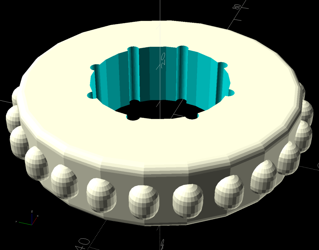
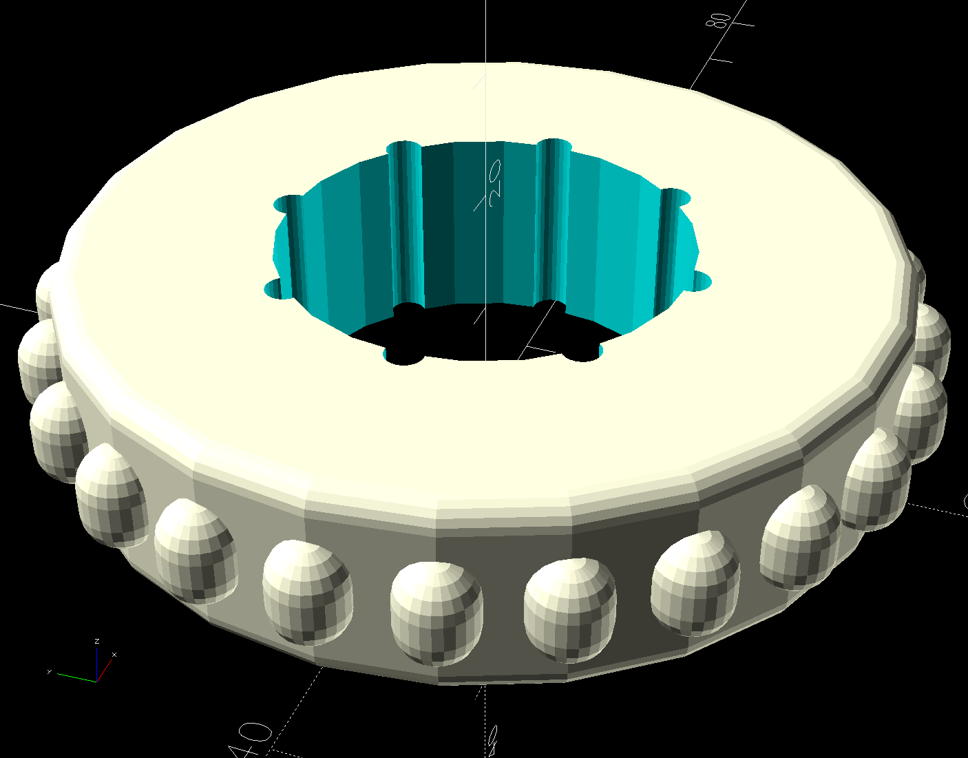
It just barely clears the curved air guide inside:
PolyDryer airlock plate – tiny fan installed
The tea bags full of desiccant allow some wind between them and the filament in the spool, but I obviously must re-think that setup. There’s enough clearance for what should be reasonable circulation, so i defined it to be good enough for now.
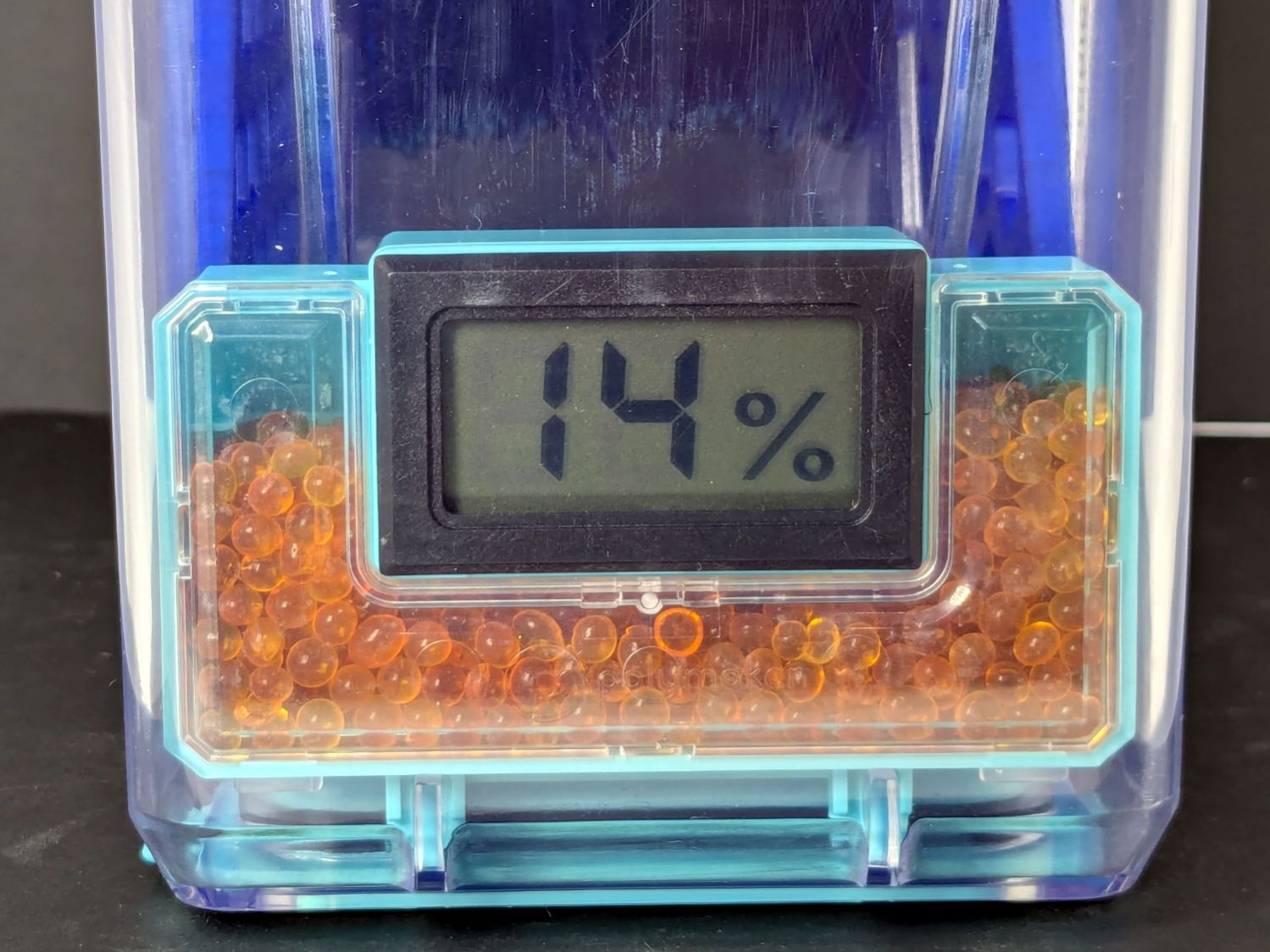
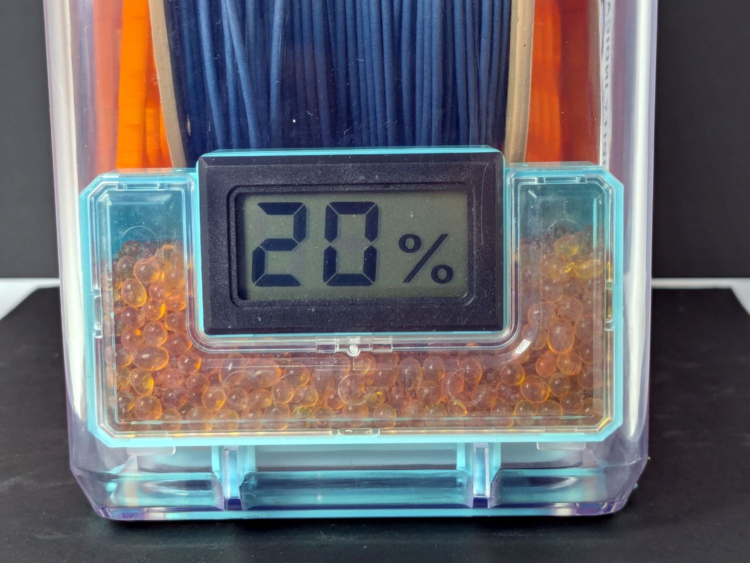
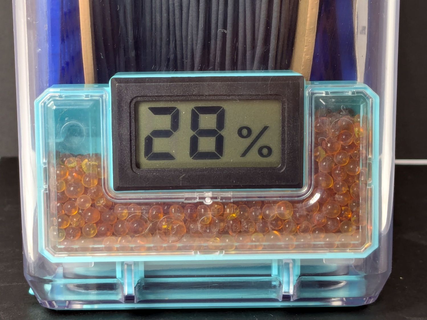
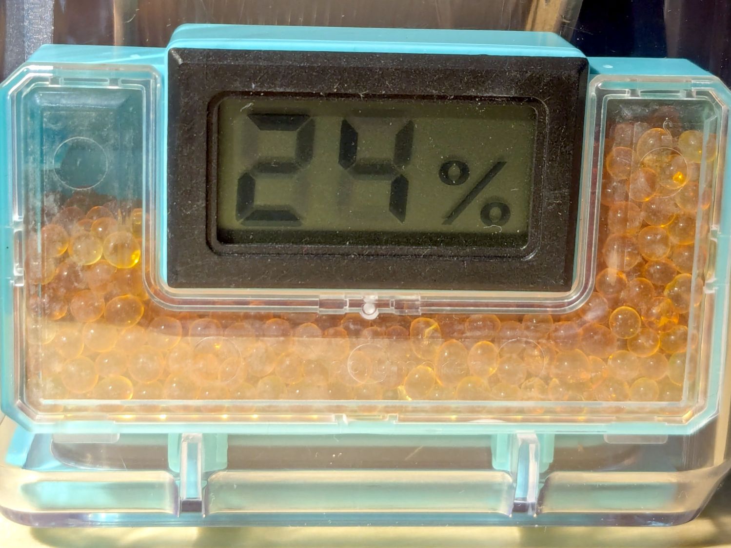
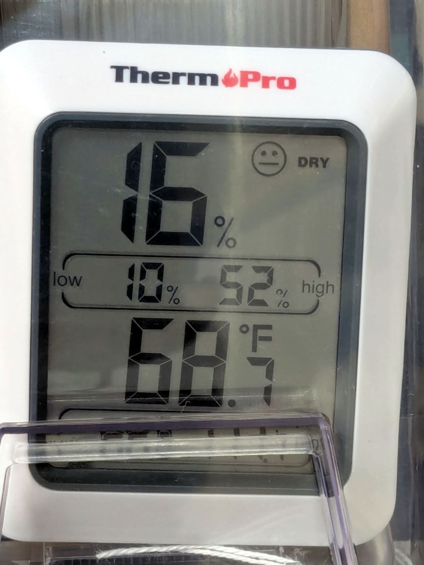
The box of TPU started at 25 %RH, dropped to 22 %RH overnight, then returned to 25 %RH the next day:
PolyDryer TPU – 25 pct RH
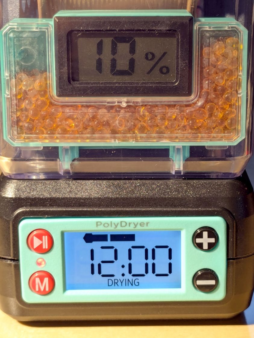
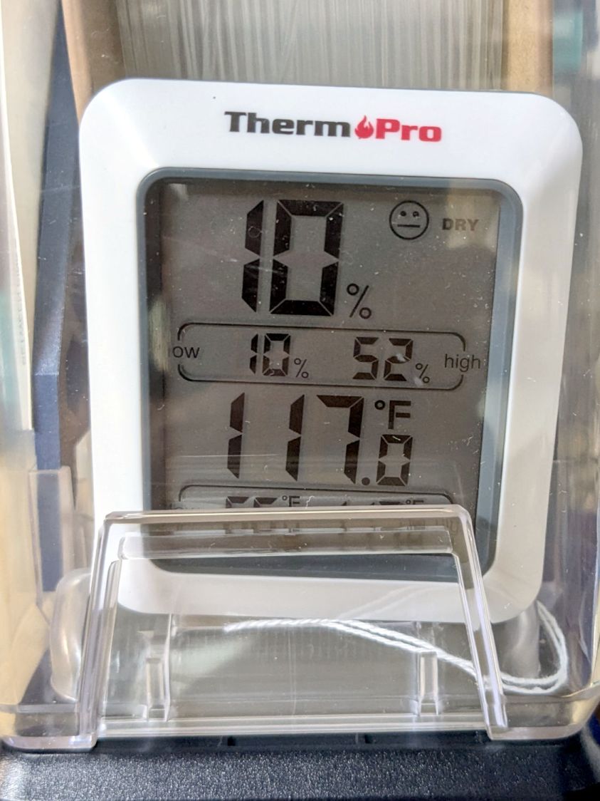
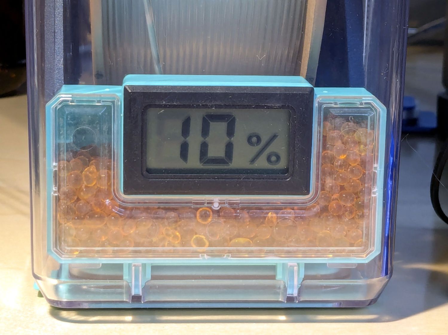
Now that I’m watching more often, I’ve seen the meter glitch to 10% for a few seconds:
PolyDryer TPU – 10 pct RH glitch
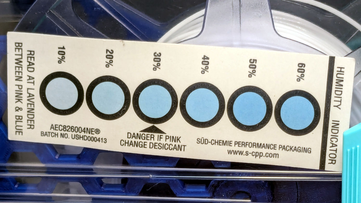
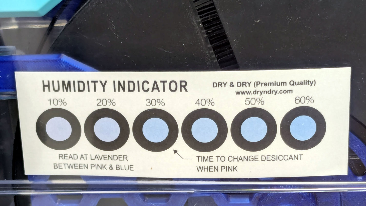
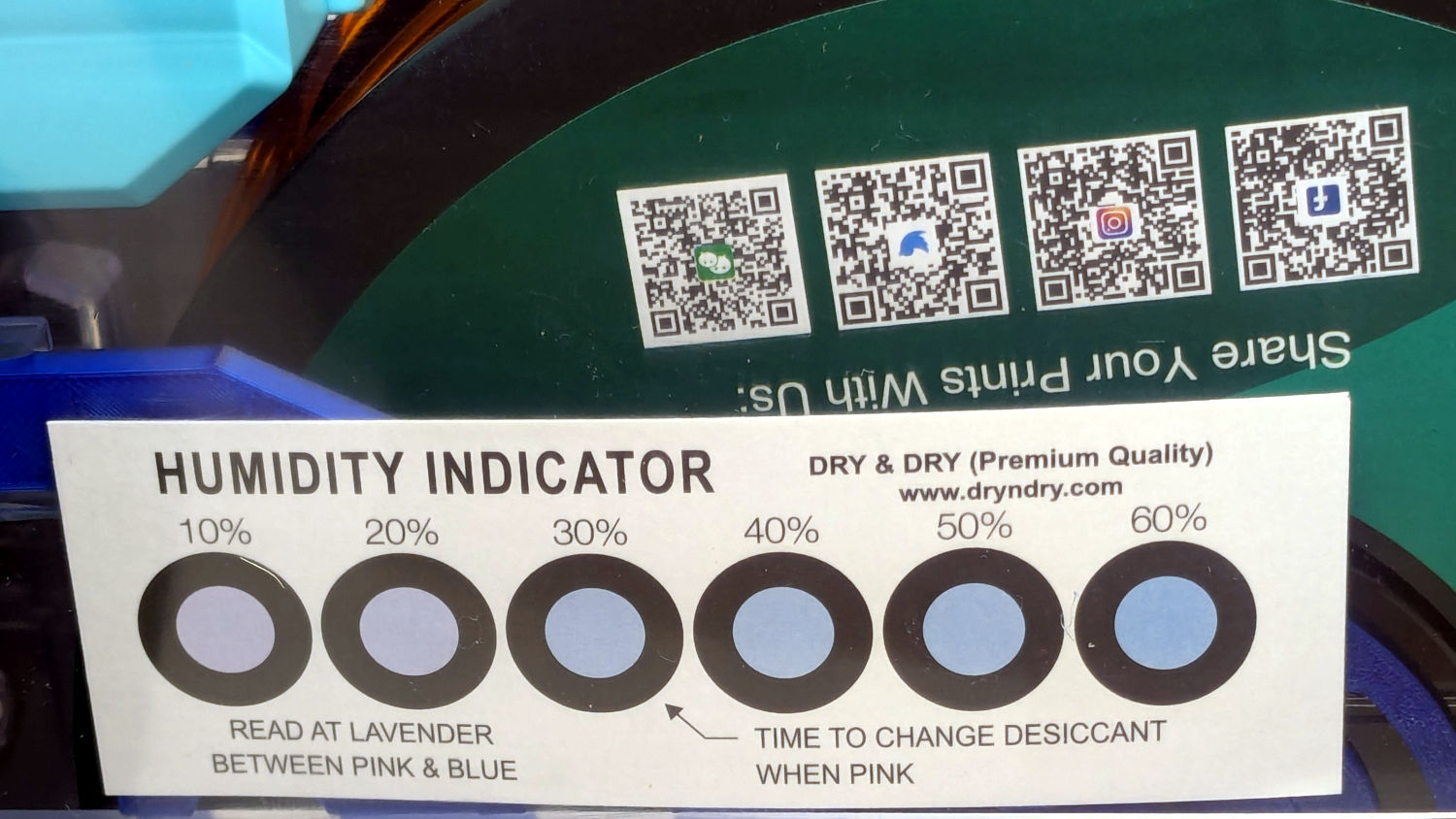
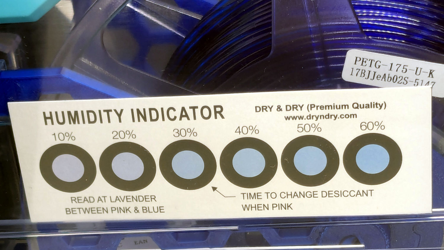
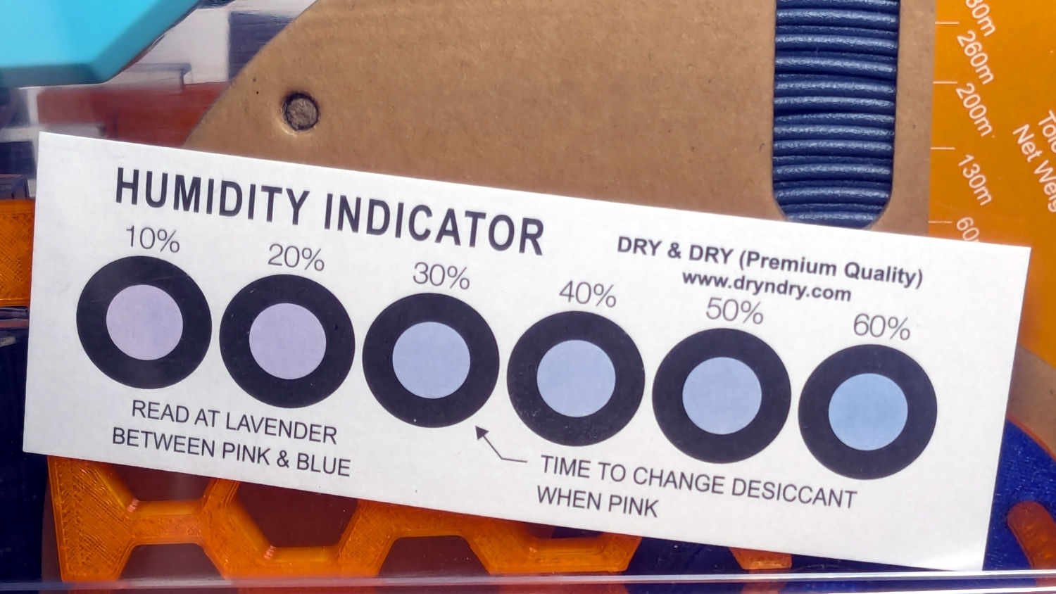
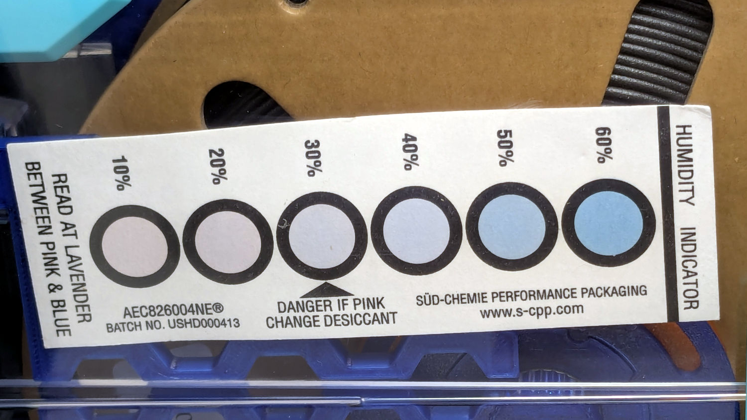
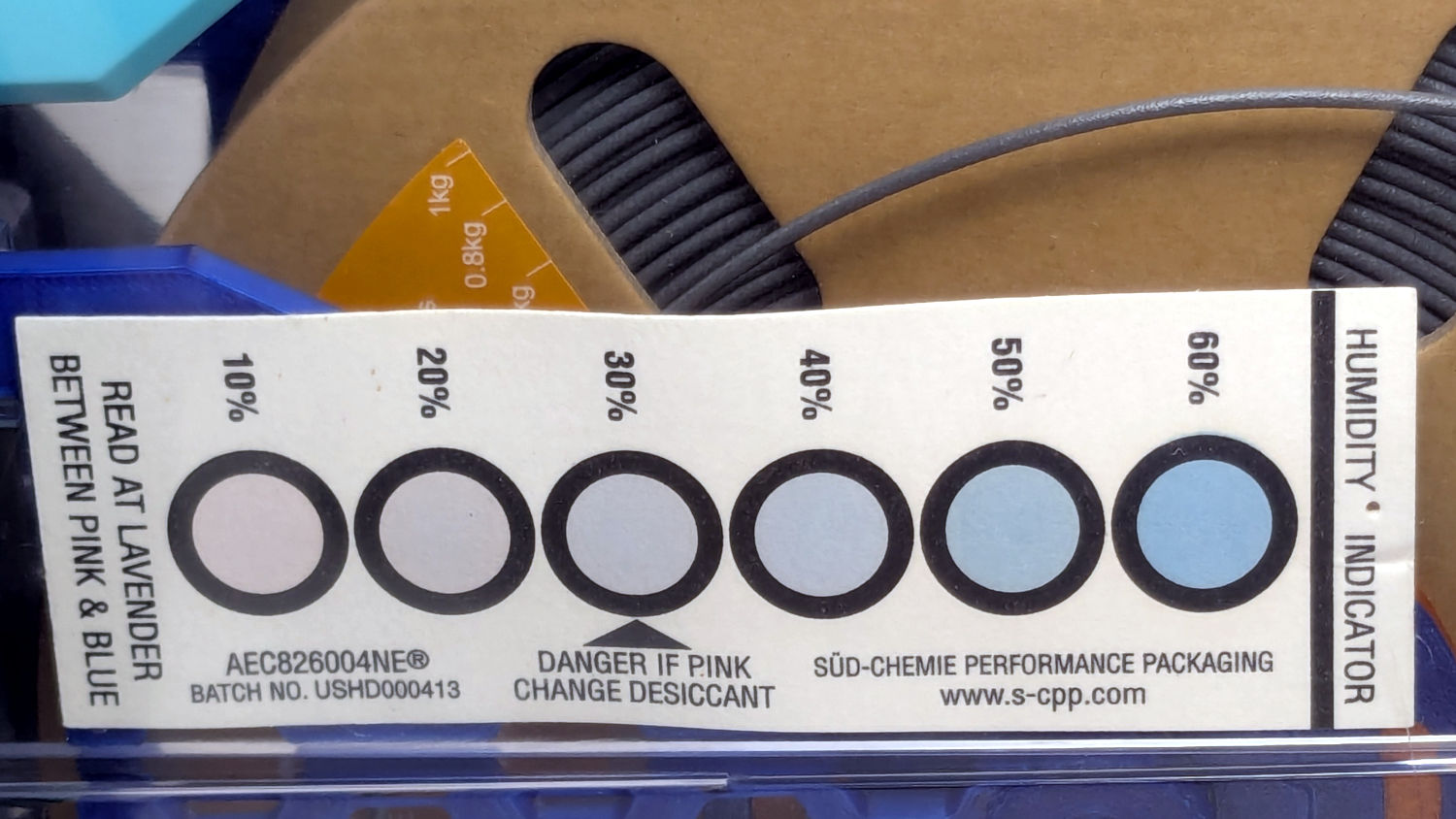
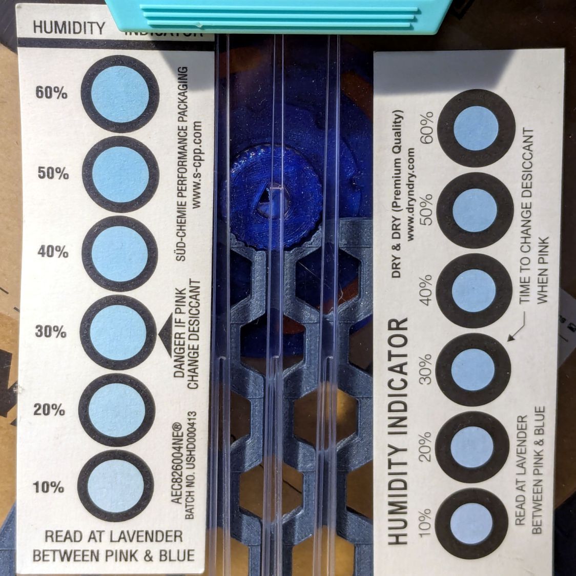
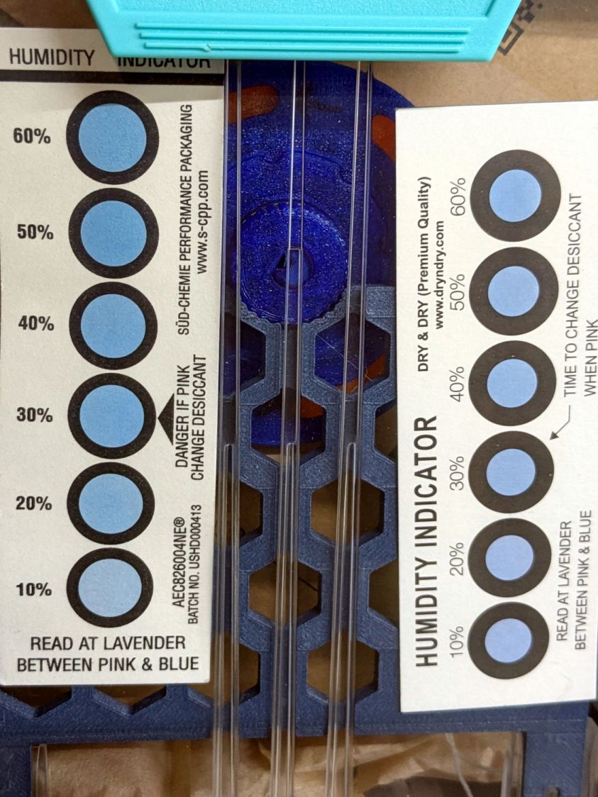
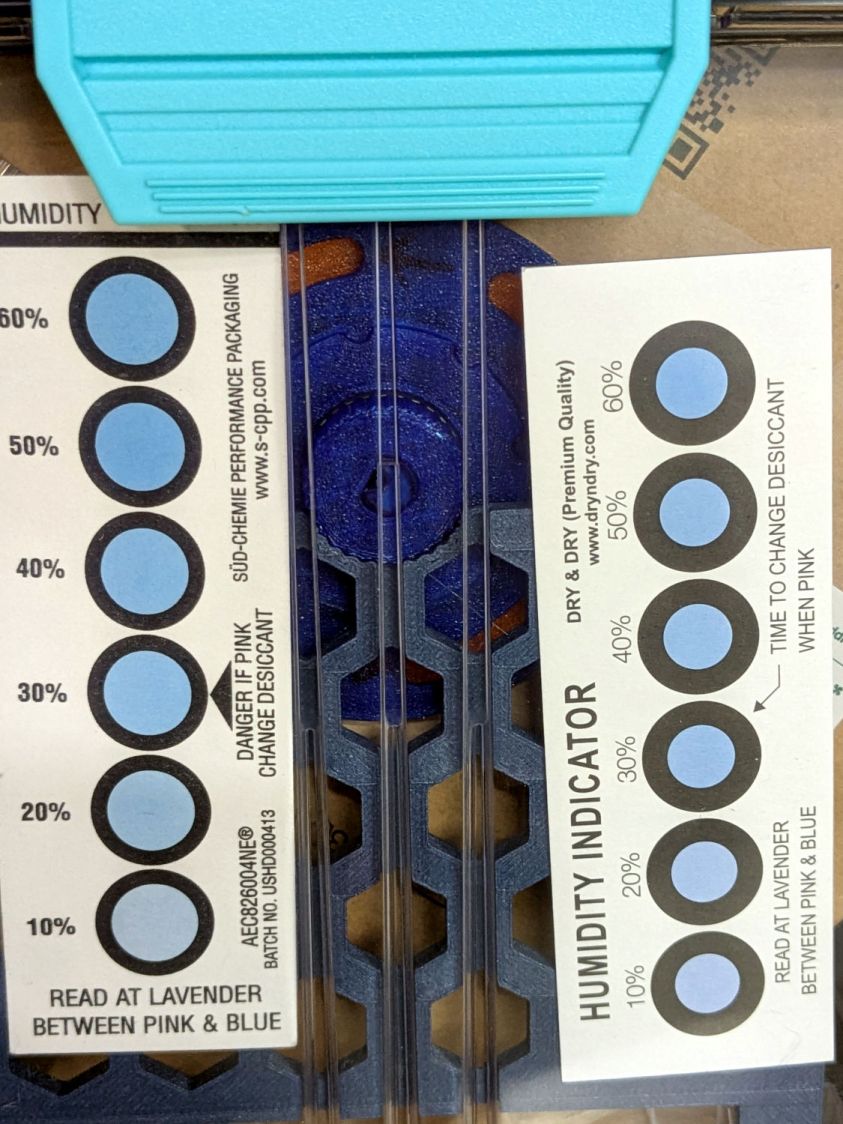
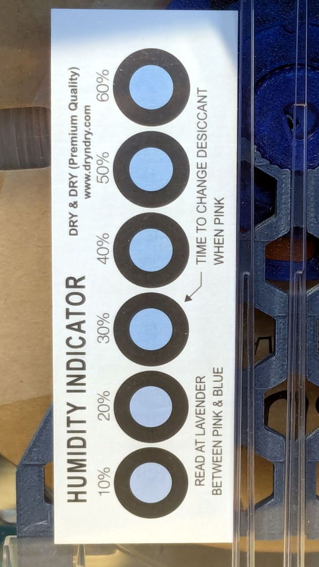
A humidity indicator card suggests the air is under 20 %RH:
PolyDryer TPU – humidity indicator card
It may be the filament can outgas water vapor as rapidly as the desiccant can remove it, but I expected the fan to make at least a little difference.
The Basement Shop has 50±5% relative humidity, with the top held down by a hulking dehumidifier (plus a box fan stirring the air) and the bottom supported by being a basement. As a result, the 3D printer filament stabilized at about 50% RH, which seemed to work well enough for PETG.
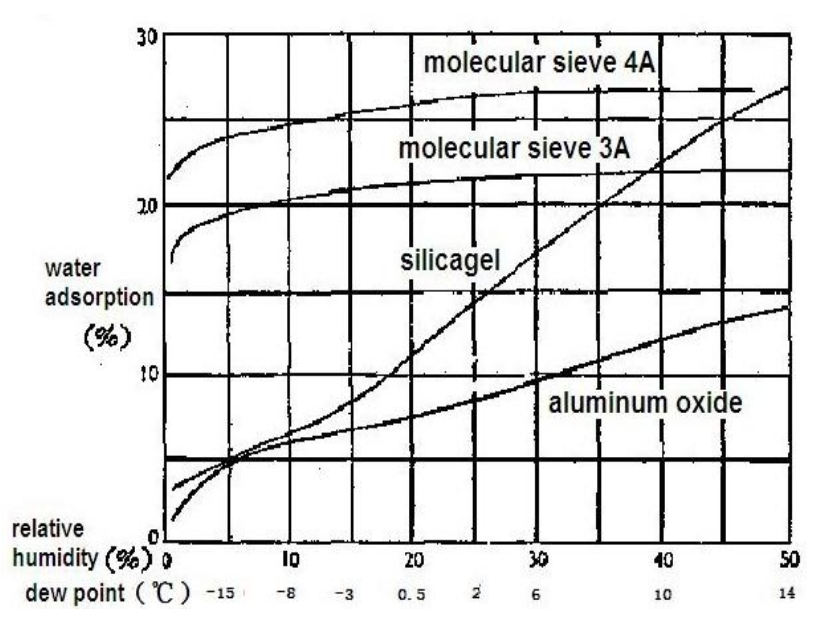
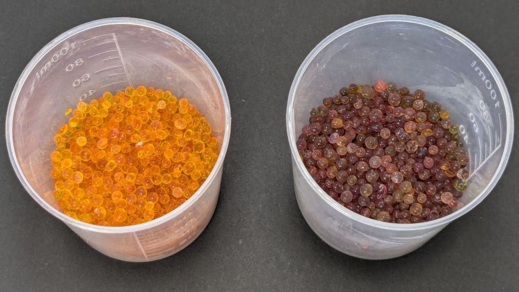
That’s activated alumina desiccant, mostly because it’s reputed to have more capacity and a lower ultimate humidity than silica gel, but it likely doesn’t make much difference.
In addition to 25 g of desiccant in the PolyDryer meter case, I dropped five teabags holding 10 g each in the bottom of the box for more capacity. I measure the desiccant by putting 75.0 g into a cup, putting 25.0 g in the PolyDryer meter box (aided by a Polydryer Desiccant Funnel), 10.0 g into four teabags, and whatever’s left into the fifth teabag, thus eliminating rounding errors in the smaller quantities.
The stabilized humidity inside the boxes seems to depend on the amount of filament on the spool:
Nearly full → 25% to 30% RH
Half full → 20%-ish RH
Nearly empty → 10% to 15% RH
I think the humidity level comes from the filament outgassing water vapor through its (limited) surface area on the outer layer around the spool. The difference between that rate and the desiccant’s ability to remove water vapor from the (unmoving) air in the box sets the stable humidity: more surface area → more water vapor → higher humidity.
After the filament eventually dries out, the humidity should decrease, but diffusion is a slow process. More likely, the humidity will remain stable as the printer pulls filament from the outer layer and exposes the somewhat wetter plastic within.
The heater and fan inside the PolyDryer base unit circulates hot air through the box around the spool, but depends on the desiccant to remove water vapor. Running the base unit for 6 or 12 hours makes little difference in the stabilized humidity, so I think the desiccant is doing the best it can as the filament outgasses more water vapor.
Using Air Exchanger vents seems to make no difference, likely because the desiccant must then pull more water vapor out of the incoming 50% RH basement air. A psychrometric chart says 50% RH air at 60 °F becomes 10% RH air at 120 °F, but moisture in the filament wrapped around the spool can’t escape any faster.
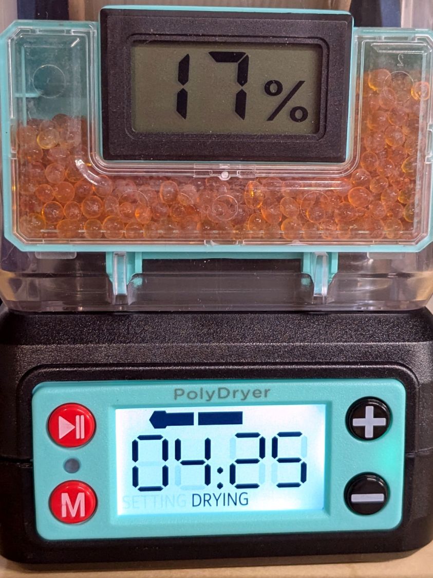
So, for example, a full spool of TPU starting at 25% RH:
PolyDryer humidity – TPU start
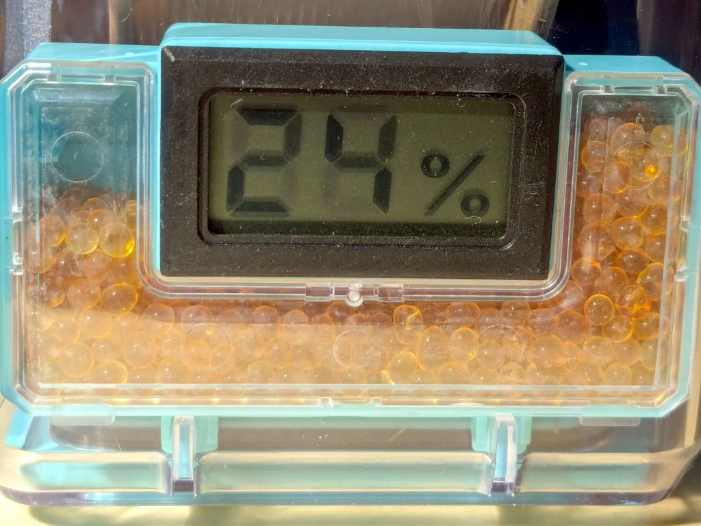
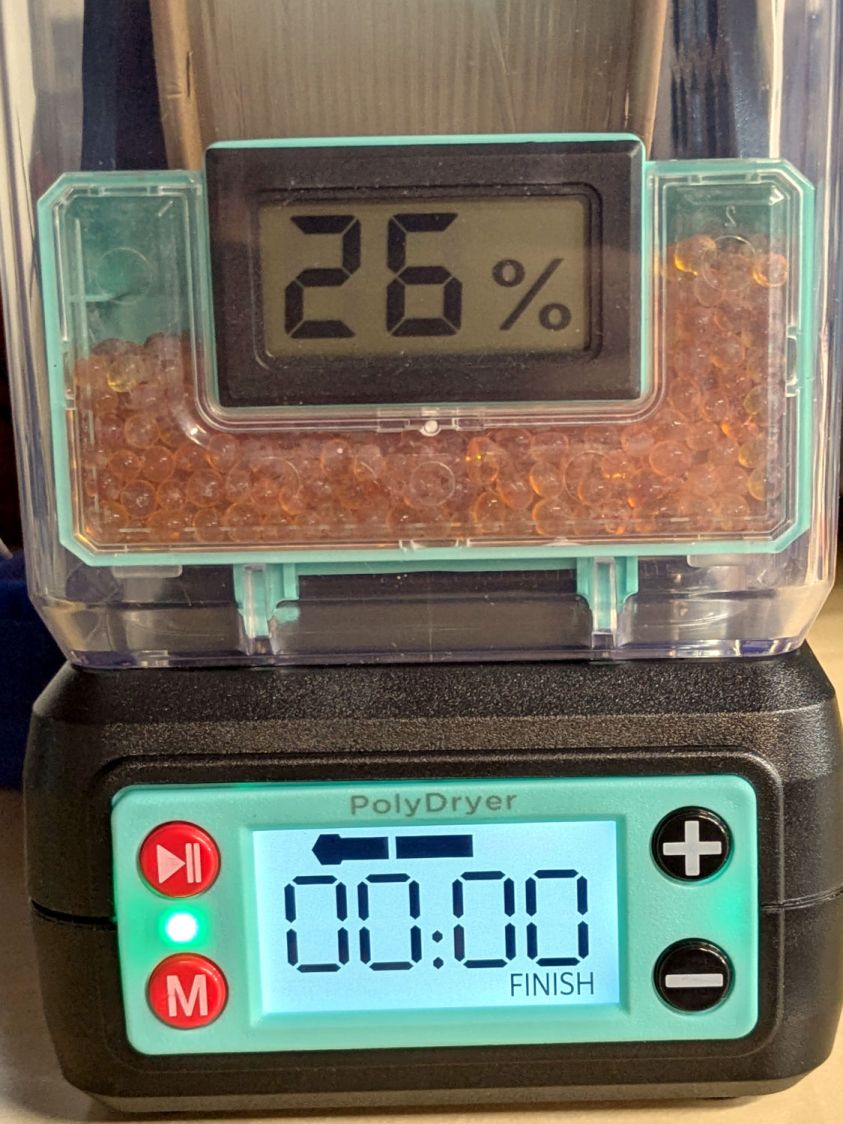
Six hours of drying pulls it down to 22%:
PolyDryer humidity – TPU finish
After sitting overnight it’s back at 25%:
PolyDryer humidity – TPU after 14 hr
Admittedly, that was with the vents in place, but the closed box started at 25% RH after sitting around for a week or so following a similar drying cycle.
The desiccant had absorbed 4 g of water since I put it in, so it hasn’t been entirely idle.
Which suggests 75 g of activated alumina desiccant is workin’ hard and doin’ swell in there, with the filament acting as an essentially infinite reservoir of water vapor.
I haven’t noticed any particular difference in PETG print quality and the TPU hasn’t gotten enough mileage to notice much trouble, but reducing the MMU3 buffer clutter was totally worth the effort.
We don’t know what the proper term might be for this part of the machine, but it looks sorta like a nose and the lights form most of a ring around it, so I’m going with “Nose Ring Lights”:
Handi-Quilter sells a ring light for machines manufactured a decade later than ours, but it uses a built-in USB jack this machine lacks.
One of two (apparently) unused M4 holes on the left side of the machine frame suggested a mounting point for a 3D printed bracket:
HQ Sixteen Nose Ring Lights – solid model
The ramp matches the 3° (-ish) mold draft of the machine frame, which I initially ignored by angling the tab, but a tilted frame looked awful; it’s now aligned with local horizontal..
A few iterations got all the pieces & holes in their proper places:
HQ Sixteen Nose Ring lights – iterations
The smaller (rampless) bracket has three LED strips, but a quick test showed more light would be better:
HQ Sixteen Nose Ring lights – bottom view
The lack of a transparent-ish cover is obviously unsuitable for a commercial product, but the key design goal is to not interfere with spreading as much light as possible across as much of the quilt as possible. The black JB Weld Plastic Bonder blobs keep the 24 VDC supply out of harm’s way, which is as good as it needs to be for now.
The bracket has three sides, because the right side of the machine has all the thread guide hardware. Putting anything over there seemed likely to interfere with either thread movement or fingers making adjustments.
Fortunately, the wider bracket doesn’t stick out too far beyond the machine frame and the doubled LED strips create a much smoother light pool:
HQ Sixteen Nose Ring lights – left front view
Yes, the quilt is focused and the LED frame is blurred.
The larger light-emitting area reduces the shadow under the left rod (supporting the ruler foot) enough to be unobjectionable.
A 0.2 mm layer thickness transforms the smooth ramp into stair steps:
HQ Sixteen Nose Ring Lights – PrusaSlicer
They’re inconspicuous after the bracket is installed.
The Chin Light ran on 12 V and these strips require 24 V, so the OpenSCAD code creates a pair of endcaps for the new supply, which is of course completely different than the old supply. Setting that up must await quilt completion.
This file contains hidden or bidirectional Unicode text that may be interpreted or compiled differently than what appears below. To review, open the file in an editor that reveals hidden Unicode characters.
Learn more about bidirectional Unicode characters
That’s the gluing “fixture” with enough steel piled on the lid to keep it from moving and machinist vises pushing / holding the hinge fragments in place.
I used the same technique as before, with duct tape aligning the loose pieces and JB Plastic Bonder sticking them together:
Sears Humidifier – right hinge outboard
The other side of that hinge shows the broken section at the end of the molded void:
Sears Humidifier – right hinge inboard
The other hinge has a 3D printed replacement end:
Sears Humidifier – left hinge inboard
The other side shows there’s not much of the original hinge left:
Sears Humidifier – left hinge outboard
I very carefully installed the lid on the newly cleaned humidifier in the Basement Shop, where it flips up and down like anything.
At the start of this year’s humidification season, I will very carefully carry the lid up the basement stairs to the Sewing Room and we’ll see how long it survives in actual use.
The auto-rewind spindles for PolyDryer boxes fit a variety of spools, but recessed hubs like this require a pair of washers to center the spindles:
Filament spool washers – recessed hub
They’re laser-cut, although you could print them easily enough:
Filament spool washers – recessed hub – installed
The size for that particular spool:
OD = 80 mm
Flange side ID = 51 mm
Nut side ID = 43
Thickness = ¼ inch, near enough
Other spools required a 3 mm shim on the flange side to sit centered in the PolyDryer boxes. Those are basically identical what you see above, with a 72 mm OD matching the flange.
The PETG-CF filament arrived on cardboard spools, which are apparently the new hotness:
Filament spool washers – printed
The 56 mm spool ID requires adapters on both sides, with the flange side getting a 4 mm shim:
Filament spool washers – printed shim – flange side
That skootches the spool over against the 1 mm shim on the nut side:
Filament spool washers – printed – nut side
It would be possible to modify the auto-rewind spindle diameters to suit, if you were a dab hand with Fusion360, but the variety of hubs around here tells me a set of cheap adapters & shims makes more sense.
You should not assume anything will fit the spools you have, no matter how much they resemble what you see above.
This file contains hidden or bidirectional Unicode text that may be interpreted or compiled differently than what appears below. To review, open the file in an editor that reveals hidden Unicode characters.
Learn more about bidirectional Unicode characters
Scan the sketch, import into Inkscape, rotate the image to correct the case taper angle vs. the page, lay lines & curves around the perimeter, align half of it at the page origin to work with OpenSCAD, export as SVG:
Cartridge – 20x102mm outline – Inkscape layout
Import into OpenSCAD, let rotate_extrude do the heavy lifting, and remove some pieces:
Cartridge Case – build view solid model
The little disk represents a fired primer you’d print separately in a different color and glue into the pocket shown in this cutaway view:
Cartridge Case – cutaway solid model
The interior void could hold sand for additional heft, as the whole thing is obviously nose-heavy; that’s certainly in the nature of fine tuning. Obviously, we are not dealing with anything that could go bang.
It builds just like you’d expect:
20x102mm cartridge – printing
Dab some adhesive on the capsule tip, ditto for the primer, stick them in place, and it’s all good.
I like the gray PETG-CF version:
20x102mm cartridges – blue gray PETG-CF
Maybe not such a good idea in this day & age. Print responsibly, as they say.
Update
Print a sabot to fit a CO₂ capsule into a genuine steel cartridge.
This file contains hidden or bidirectional Unicode text that may be interpreted or compiled differently than what appears below. To review, open the file in an editor that reveals hidden Unicode characters.
Learn more about bidirectional Unicode characters
When our stick blender (Cusinart CSB-77, with an instruction manual dated 2011) failed, I dropped fifteen bucks on the shortest one we could find, which turned out to be inconveniently long for the shorter member of the user community. The old one recently emerged from the depths of the bench for triage; the failure was in the coupler between the motor and the blade shaft, but required complete disassembly before trying to repair it.
Pry out two obvious plastic plugs, remove two screws holding the top of the handle together, pull the handle apart, and reveal a PCB with a discrete diode bridge and an open-frame switch:
Stick blender coupler – PCB
Fortunately, the wire colors matched my preconception. Unsolder the wires to get that side of the handle off.
Un-bend the tab holding the metal shell to the plastic frame and pull it off, whereupon the frame halves unsnap to release the motor:
Stick blender coupler – shell removed
The white nylon (?) coupler on the motor shaft pries off the splined motor shaft:
Stick blender coupler – motor shaft splines
That black ring inside the coupler should be on the blade shaft:
Stick blender coupler – blade shaft
It apparently got jammed in the coupler when the shaft’s drive dogs / splines (barely visible down inside) ripped up the coupler. I don’t know if that was a sudden failure or the end result of gradually accumulating damage, but the inside of the coupler was badly chewed up.
Dismantling the blade unit requires prying three plastic clips back, one at a time, while pushing upward on the intricate black plastic fitting around the shaft:
Stick blender coupler – blade housing clips
That let me ease a drop of oil down the shaft to what looks and feels like a plastic sleeve bearing near the blade end of the housing; oil should not be needed on a plastic bearing, but it definitely improved the bearing’s attitude. The snap ring securing the shaft is far enough away to prevent me from even trying to remove it, because I know there is no way I can reinstall it:
Stick blender coupler – blade shaft snap ring
Some Xacto knife action removed the shredded plastic to reveal the remains of four slots for the blade shaft’s two drive dogs / splines:
Stick blender coupler – OEM coupler end view
Measuring All. The. Things. produced a reasonable solid model of the slots:
Stick Blender drive coupler – splines – solid model
Removing those from a model of the coupler defined the shape:
Stick Blender drive coupler – PrusaSlicer
As usual, having one in hand let me check the fit and, after a few tweaks, the next one was Just Right™.
The other end of the coupler is a simple cylinder sized for a firm press fit on the motor shaft splines:
Stick blender coupler – new coupler detail
My coupler is chunkier than the OEM coupler, because there was enough room in there and PETG-CF, being weaker than nylon, needs all the help it can get:
Stick blender coupler – new coupler installed
It’s one of the few things I’ve printed with 100% infill. If when that plastic fails, I’ll try something else.
Put the little rubber ring on the blade shaft and reassemble everything in reverse order:
Stick blender coupler – mating ends
The blender works as well as it ever did, while the halves couple and uncouple the way they should, so we’ll declare victory and keep the new blender as a backup.
This file contains hidden or bidirectional Unicode text that may be interpreted or compiled differently than what appears below. To review, open the file in an editor that reveals hidden Unicode characters.
Learn more about bidirectional Unicode characters