Although the laser ramp test fixture looked good, Brent wondered what a real test box would reveal about the Prusa MK4’s Input Shaper resonance control.
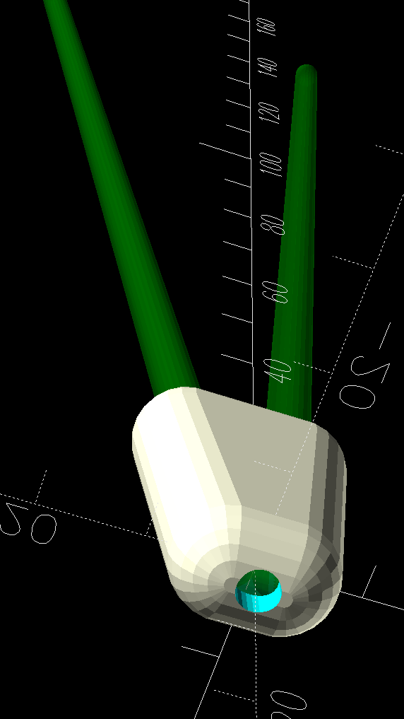
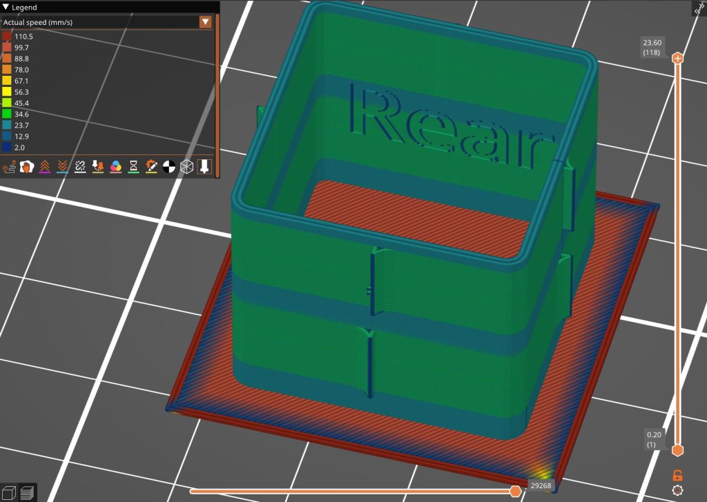
Loading the STL into PrusaSlicer, adding a text label to remind me which way it printed, then slicing with my PETG-CF profile shows the “Actual Speed”, which seems to take acceleration into consideration:
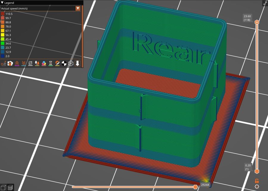
The colors in the legend don’t quite match the colors on the model, but the greenish layers with the jolts trundle along in the mid-20 mm/s range and the blue-ish straight-through layers at 30-ish mm/s.
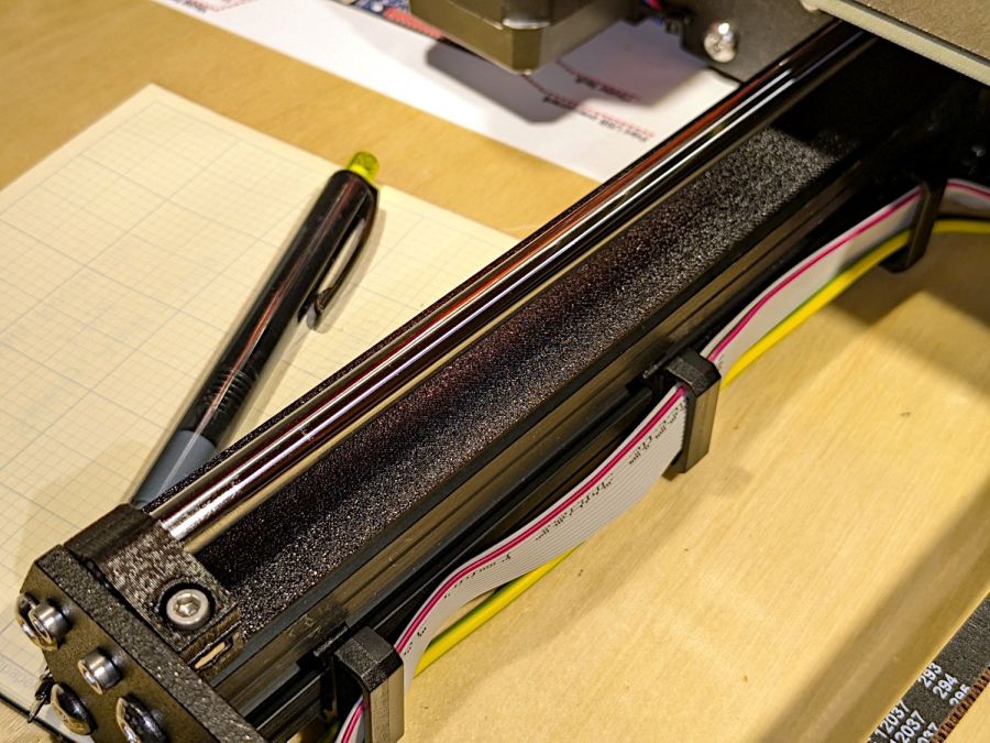
Eryone PETG-CF has a somewhat fuzzy appearance that seems not characteristic of other brands, so I’ll try something else when these spools run out:
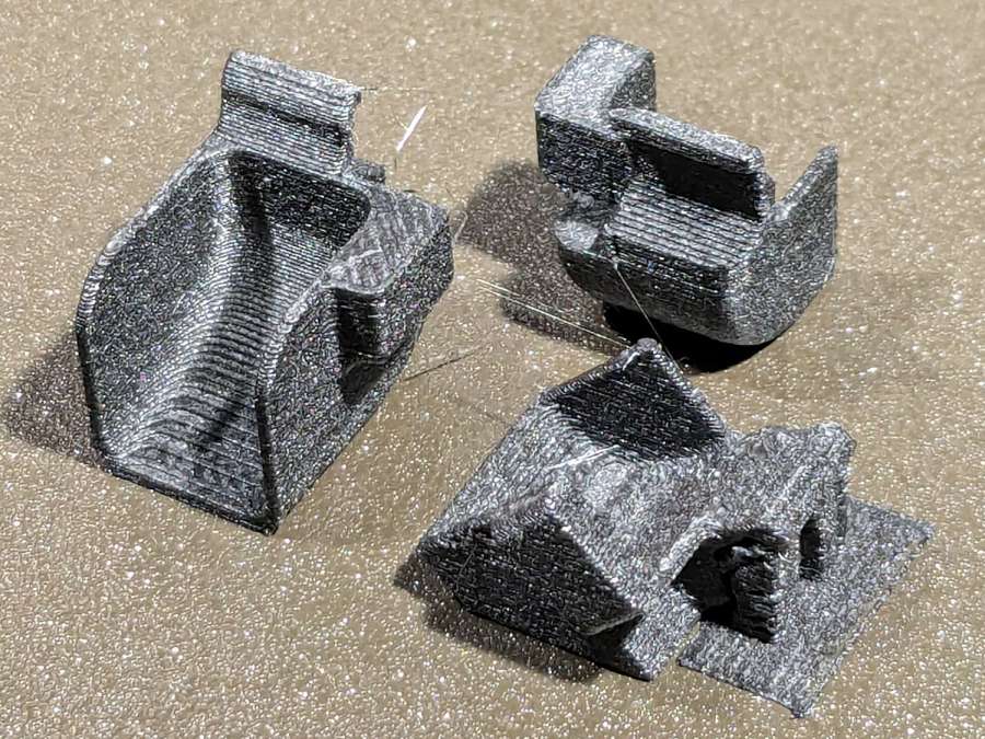
The right side of the box (as oriented on the platform) got all the layer retractions and came out festooned with PETG hairs:
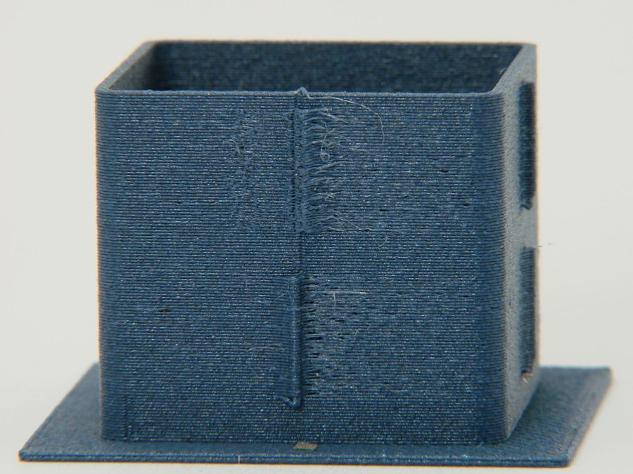
You can check my labels by tracking the small retraction zit sticking up from the top layer; I got it wrong the first time. Open the images in a new tab to see more pixels.
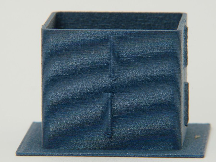
The front:
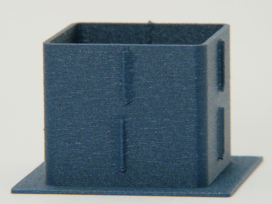
The left:
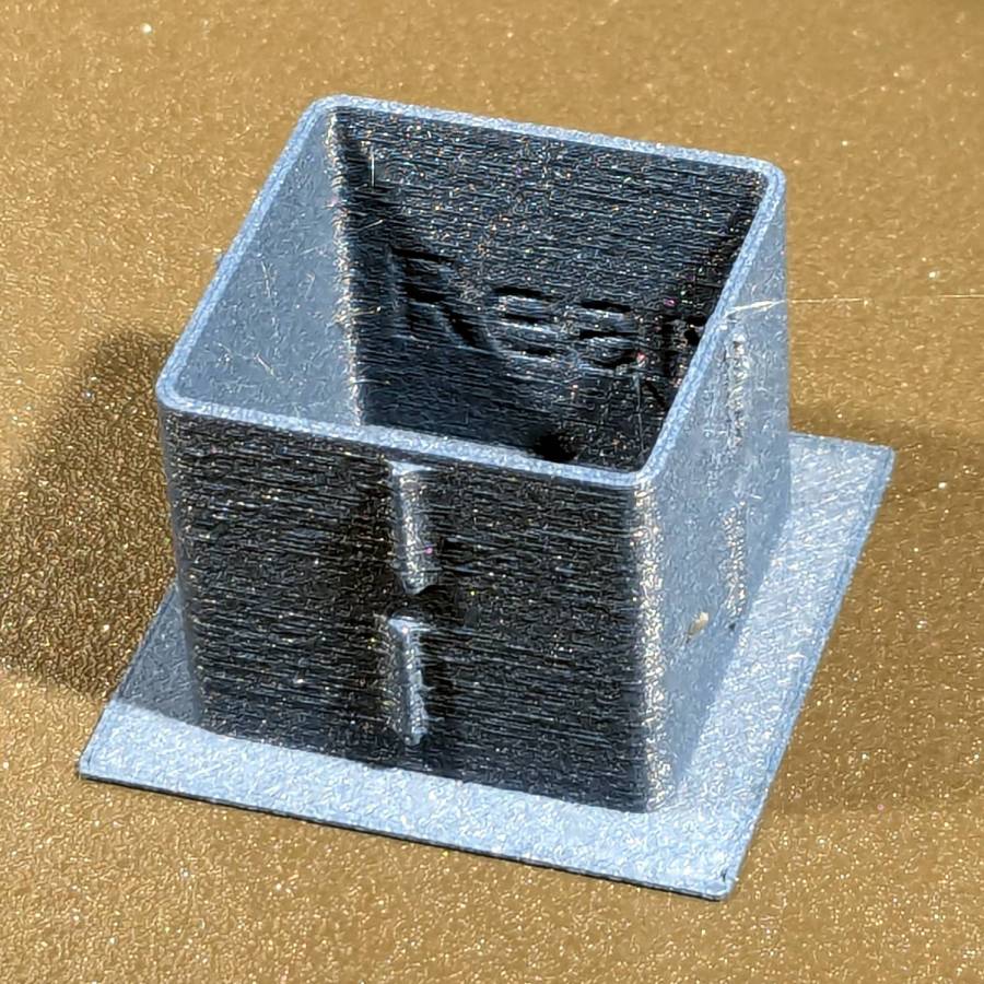
And the rear:
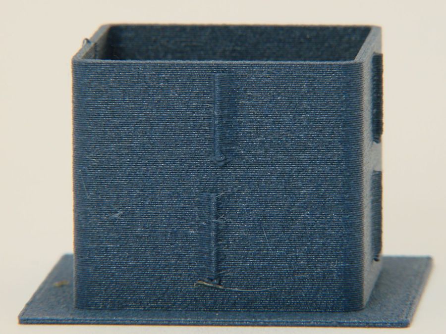
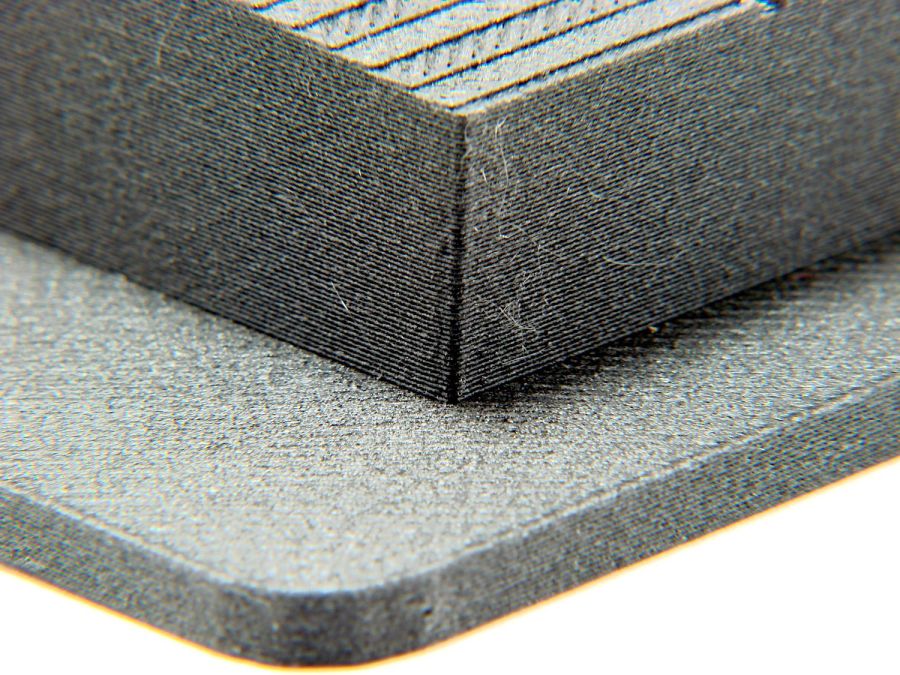
You can barely see the shadow of the “Rear” text on the surface, even though the wall is two threads thick and the text is indented by 0.2 mm, about half the thread width.
As far as I can tell, the MK4 Input Shaper compensation does a great job of suppressing resonance or wobble in all directions.
Looks good to me!