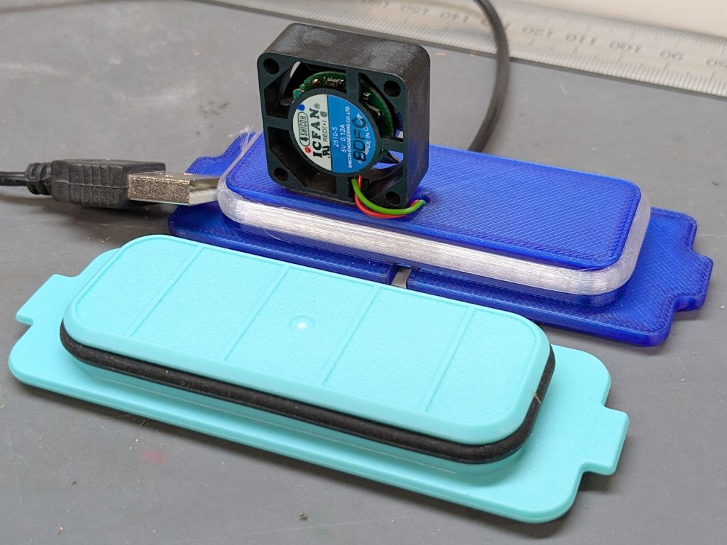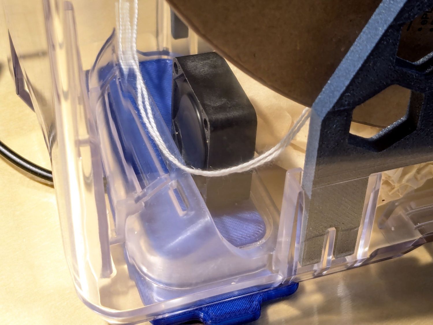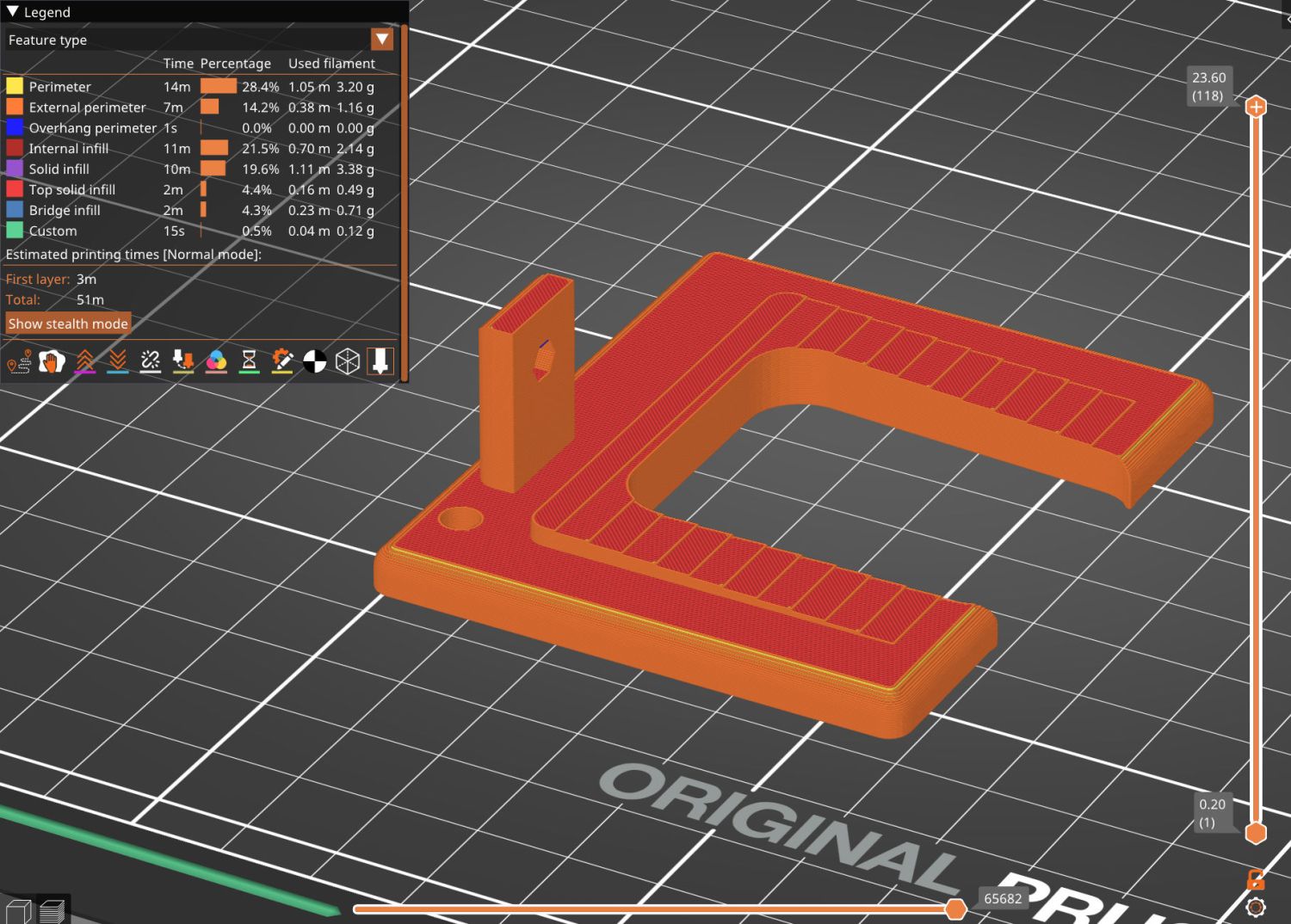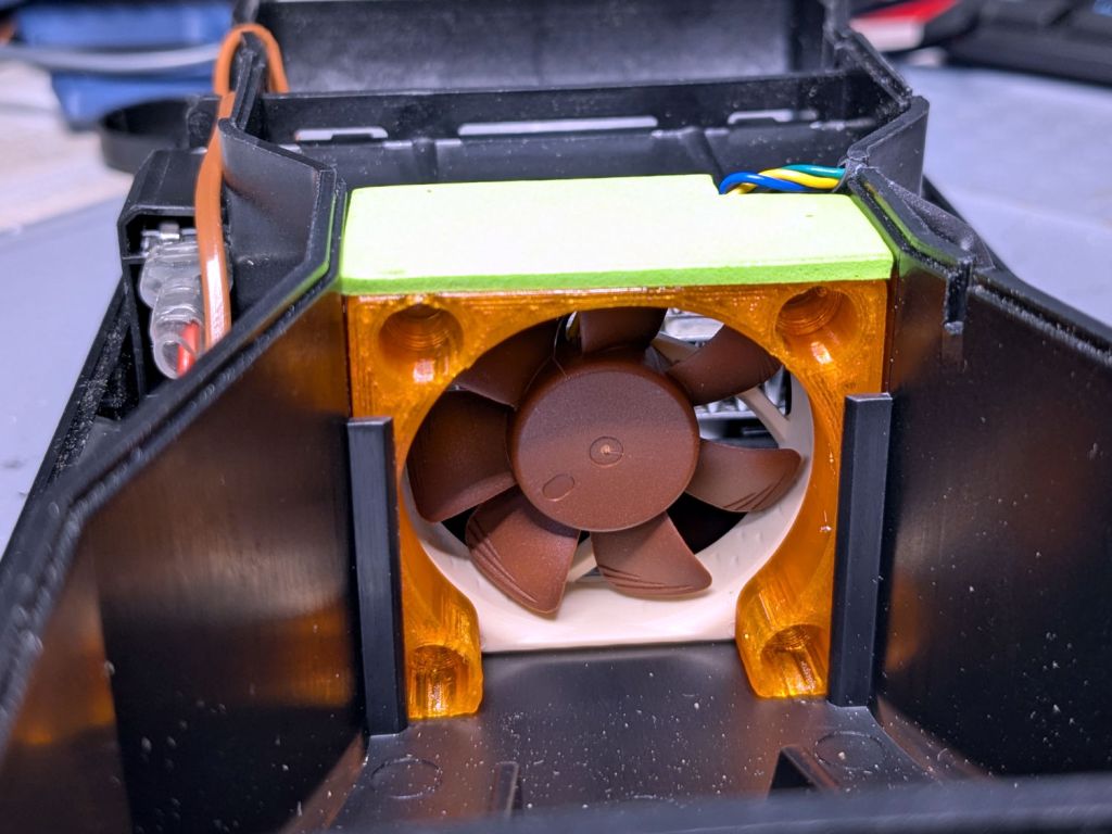
The OEM fan inside the PolyDryer is annoyingly loud, even to my deflicted hearing, so I printed a Noctua NF-A4x10 fan adapter and installed a much quieter fan:

The adapter is upside-down from the suggested orientation, I didn’t bother screwing it to the fan because it has sleeves fitting into the fan screw holes, the slot holds everything together, the vivid green EVA foam sheet sits atop a craft adhesive sheet (both cut with scissors!) ensuring they don’t part company, and it works just fine.
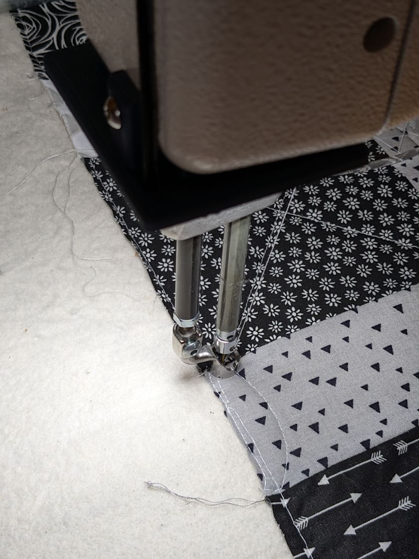
Of course, the OEM fan has a three-wire cable and the Noctua has a four-wire cable:
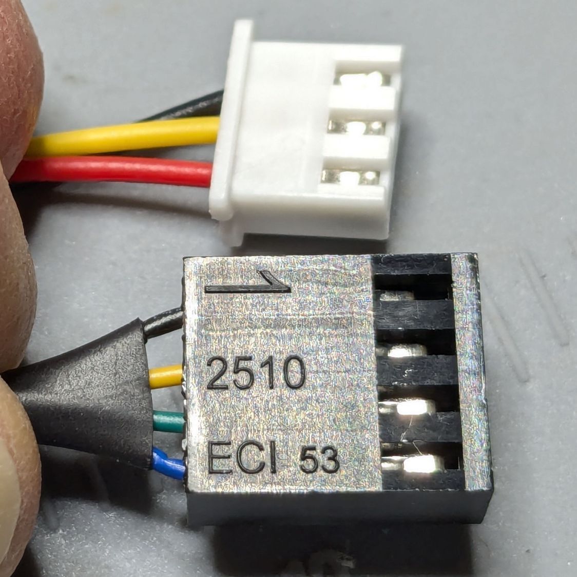
Although you can’t quite make it out on the white plastic, both connectors have their Pin 1 marks adjacent to each other. I oriented them like that to put the pin release latches on top; a foolish consistency is the hobgoblin of small minds.
Fortunately, Noctua documents their pinout, a bit of probing verified the OEM fan pinout (which does not match the Noctua 3-wire pinout), and the Basement Warehouse Wing emitted an assortment of matching JST XHP connectors. Chop off the black connector and rewire it in a 3-pin XHP connector:
- Pin 1 = OEM Red → Noctua Yellow = +24 V
- Pin 2 = OEM Yellow → Noctua Green = Tachometer
- Pin 3 = OEM Black → Noctua Black = Ground / Common
- unused = Noctua Blue = PWM Speed Control
Which is barely visible plugged into the control PCB on the left:
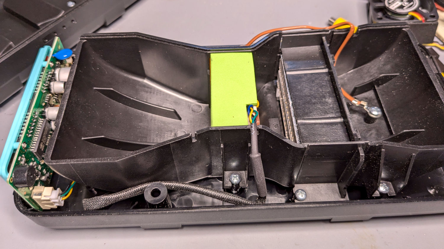
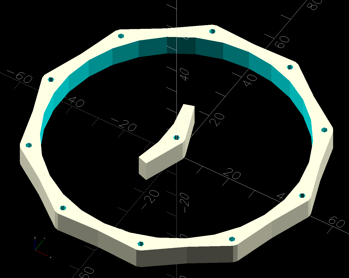
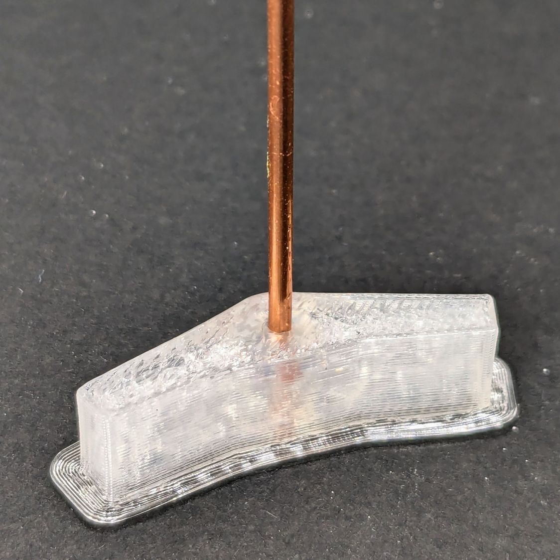
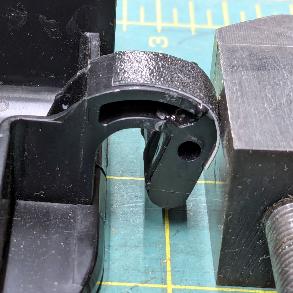
The brown thermocouple wire in the upper right didn’t start out in the notch intended to pass it out of the air flow downwind of the heater:
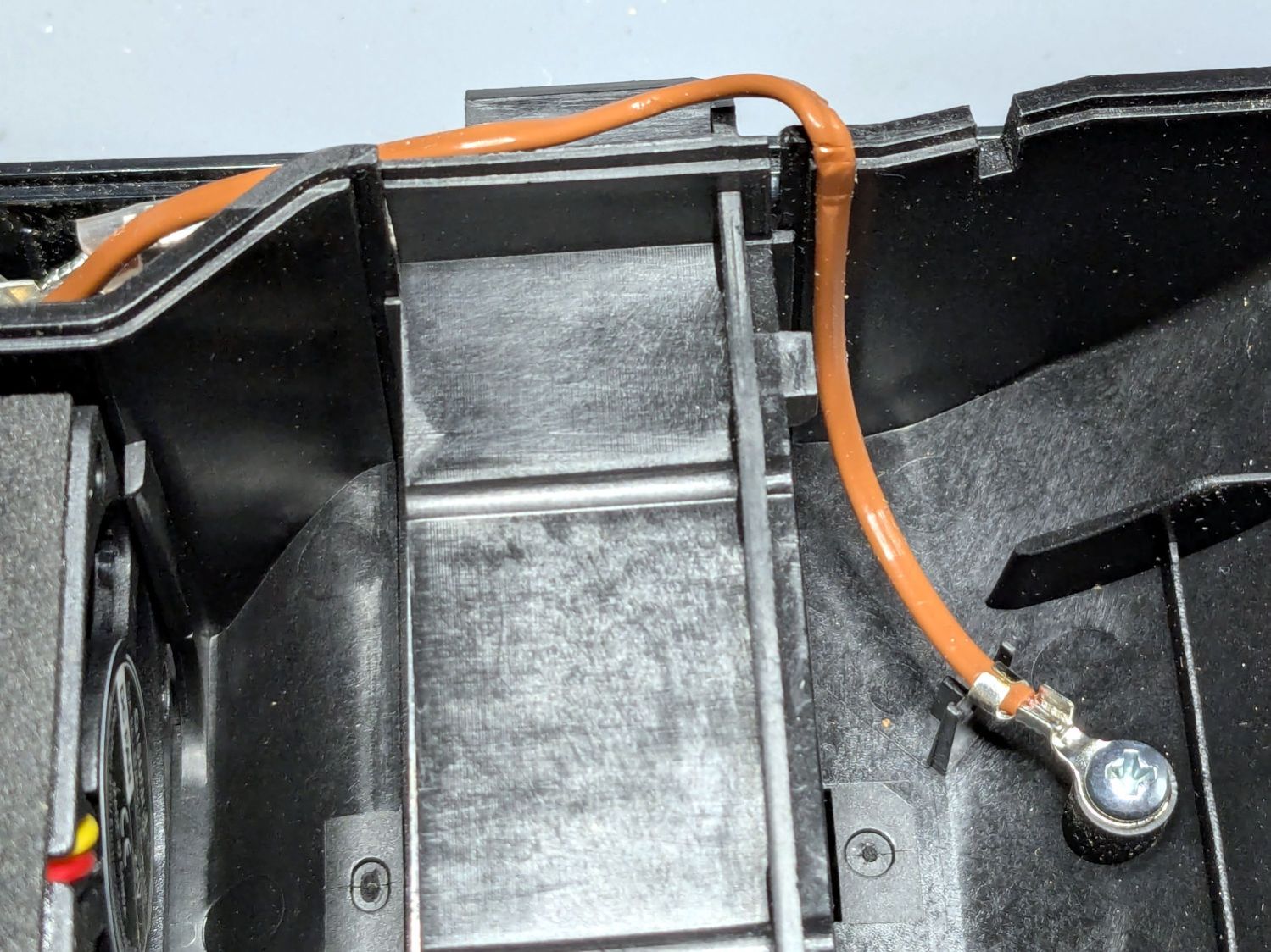
The wire is exceedingly stiff and requires some persuasion, but it will eventually stay in that slot.
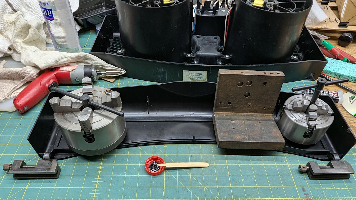
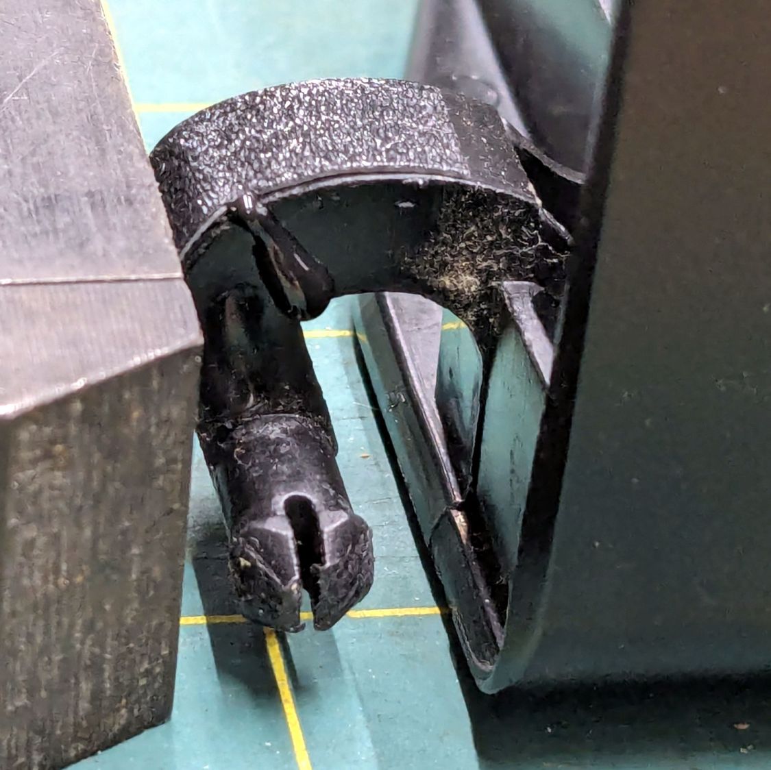
One of the PolyDryer modifications (which I can no longer find) suggested improving the vent openings, because the default slats block more than half of the surface area:
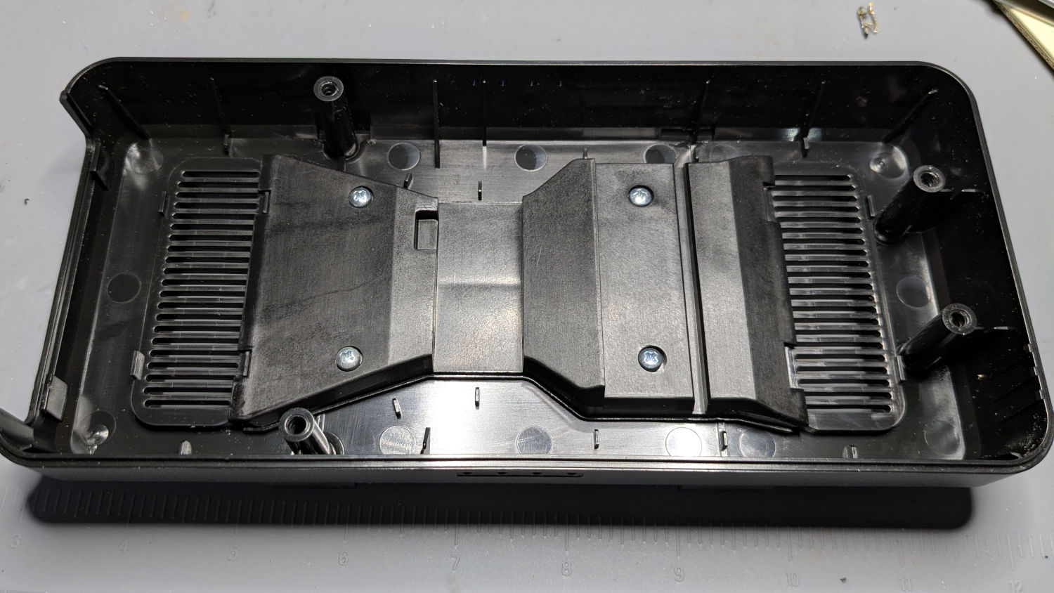
I chopped out all but three of the slats and stuffed an arch of aluminum window screen into each recess:

Admittedly, it looks a bit raggedy:

As far as I can tell without actually measuring anything, the air flow has increased.
Now, to see how whether all that makes any difference.