
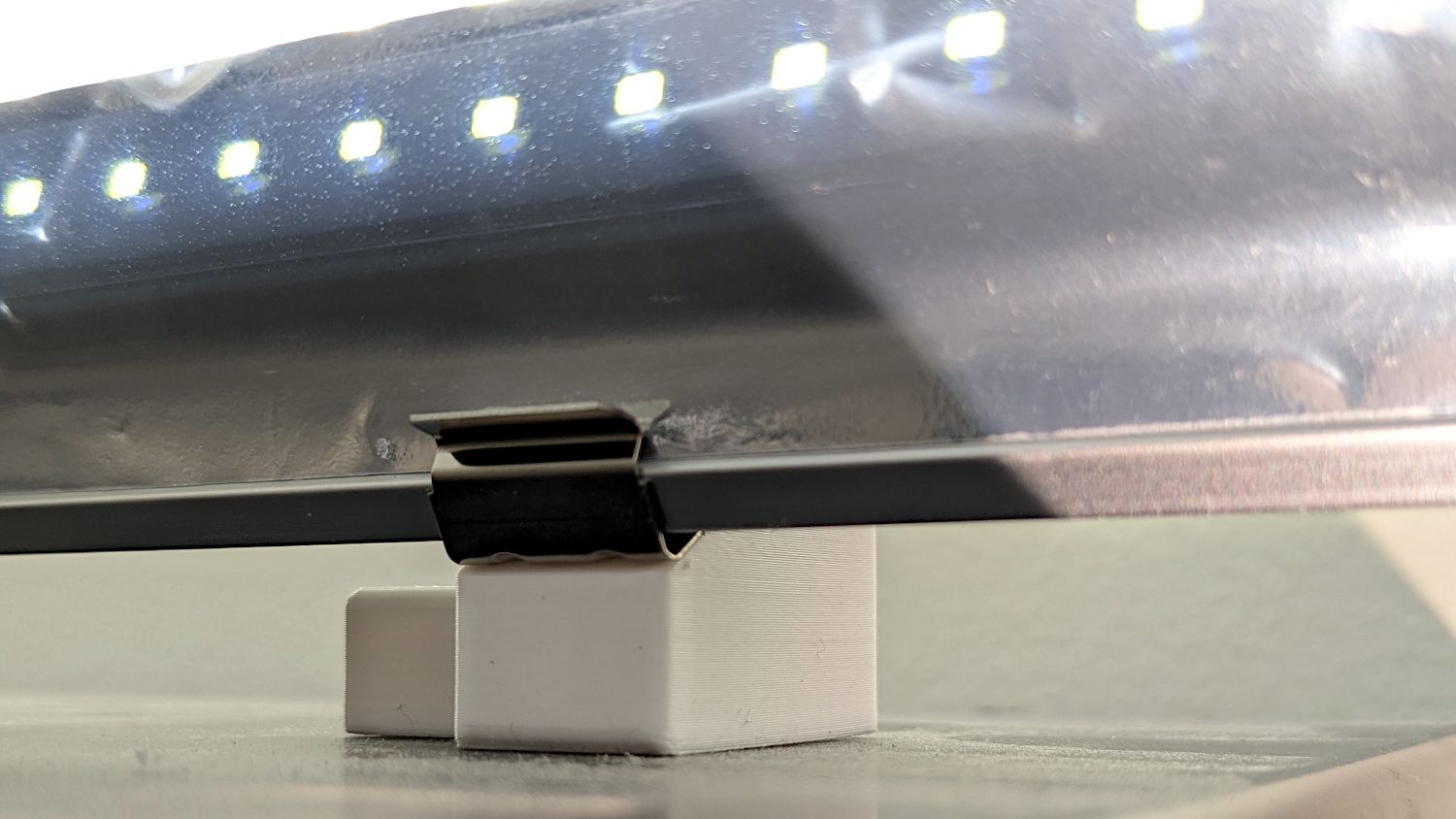
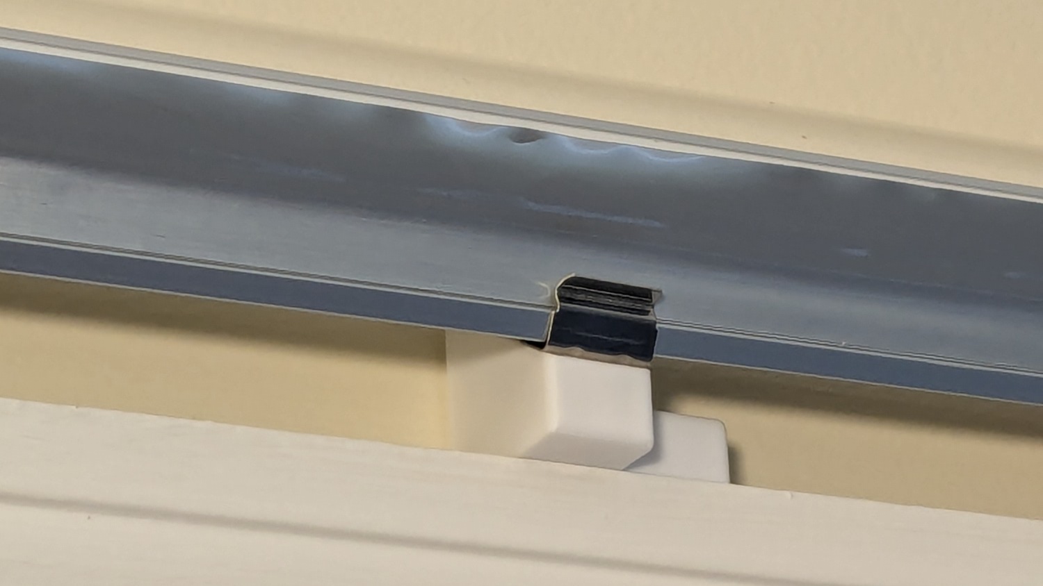
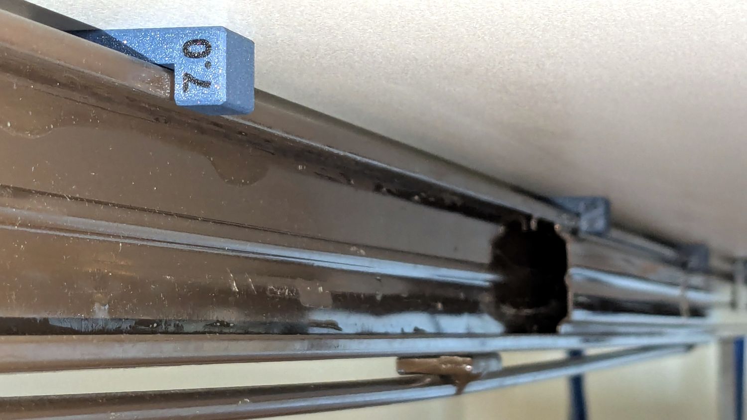
The remote control for the floor lamp across the Reading Room will never again wander away into the clutter:

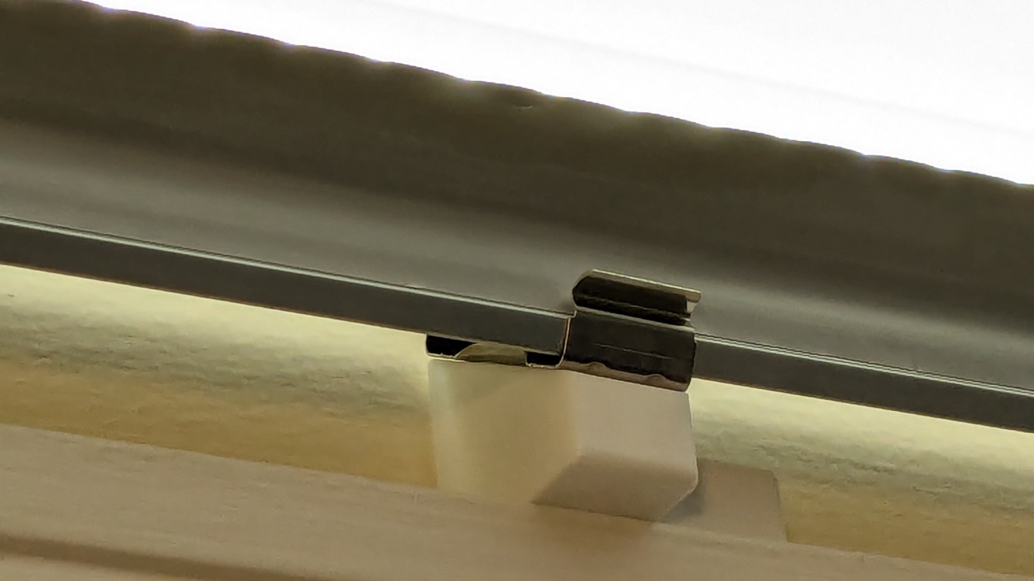
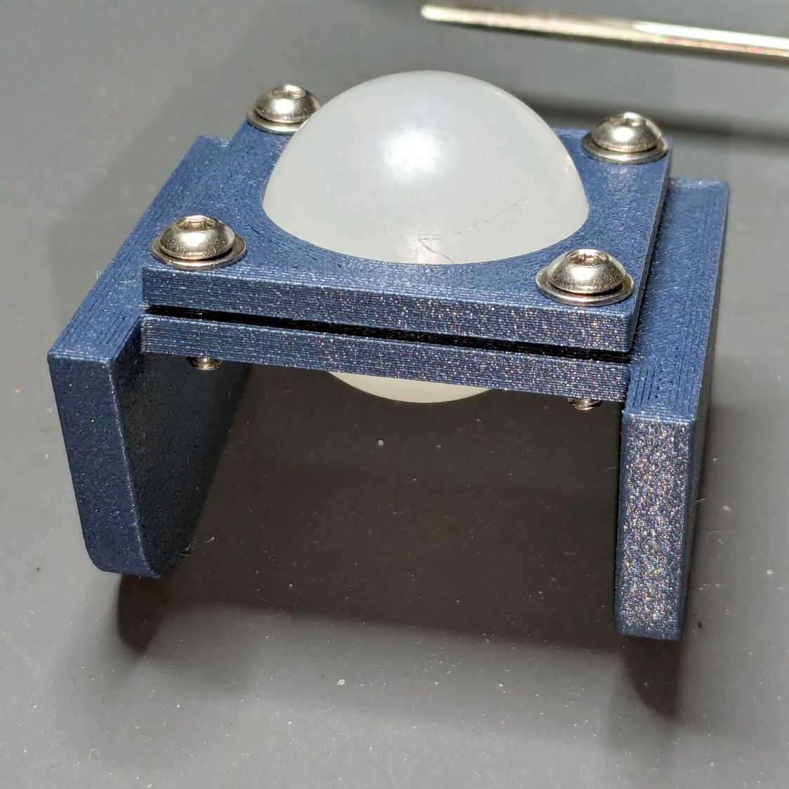
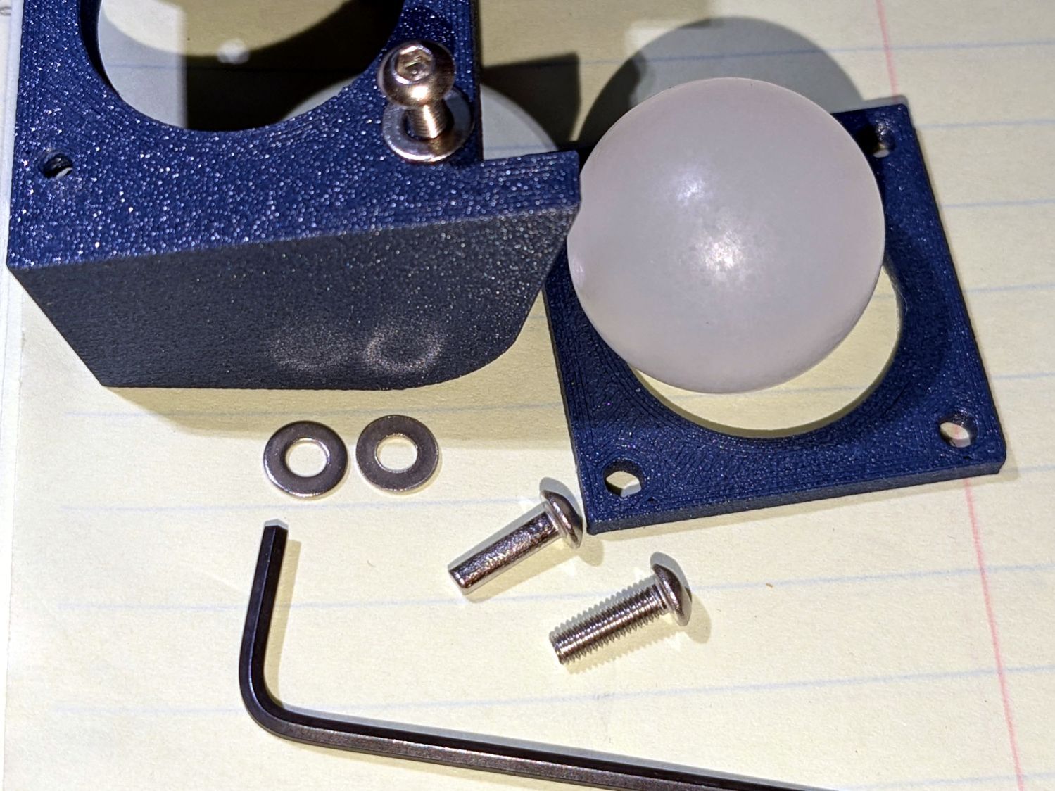
The magnet in its back snuggles against a steel disk embedded in the holder:

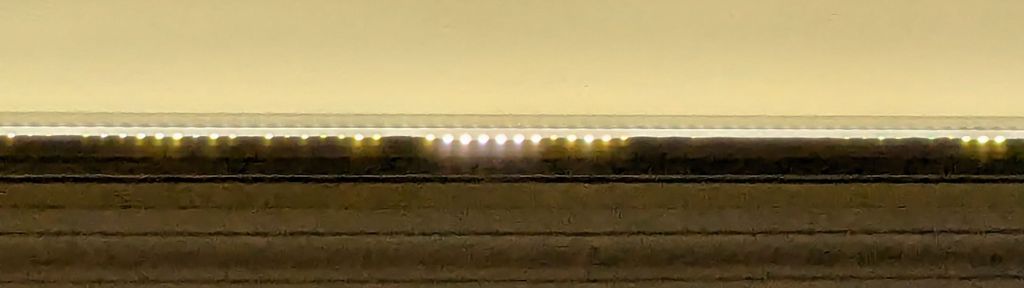
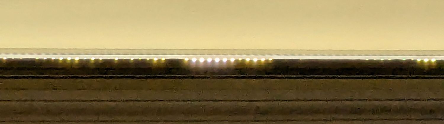
A magnetic field visualization sheet revealed the magnet:

Extract the remote’s profiles with a contour gauge:

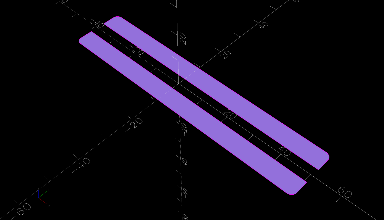
Trace the outlines and lay smooth curves around them with Inkscape:

They needed a slight lengthening to account for the gauge pin diameter & deflection, but this isn’t a precision project.
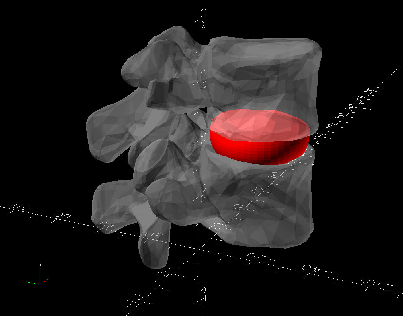
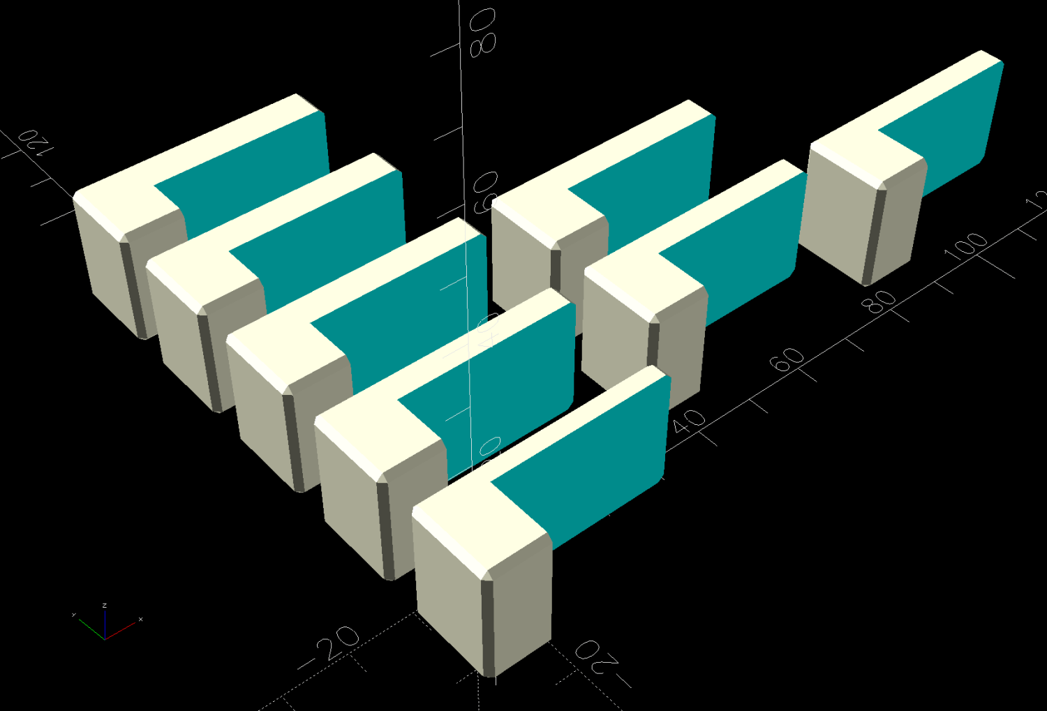
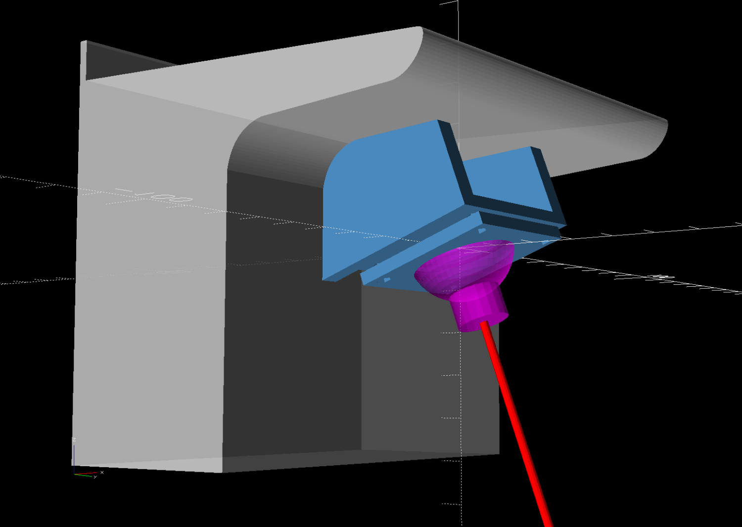
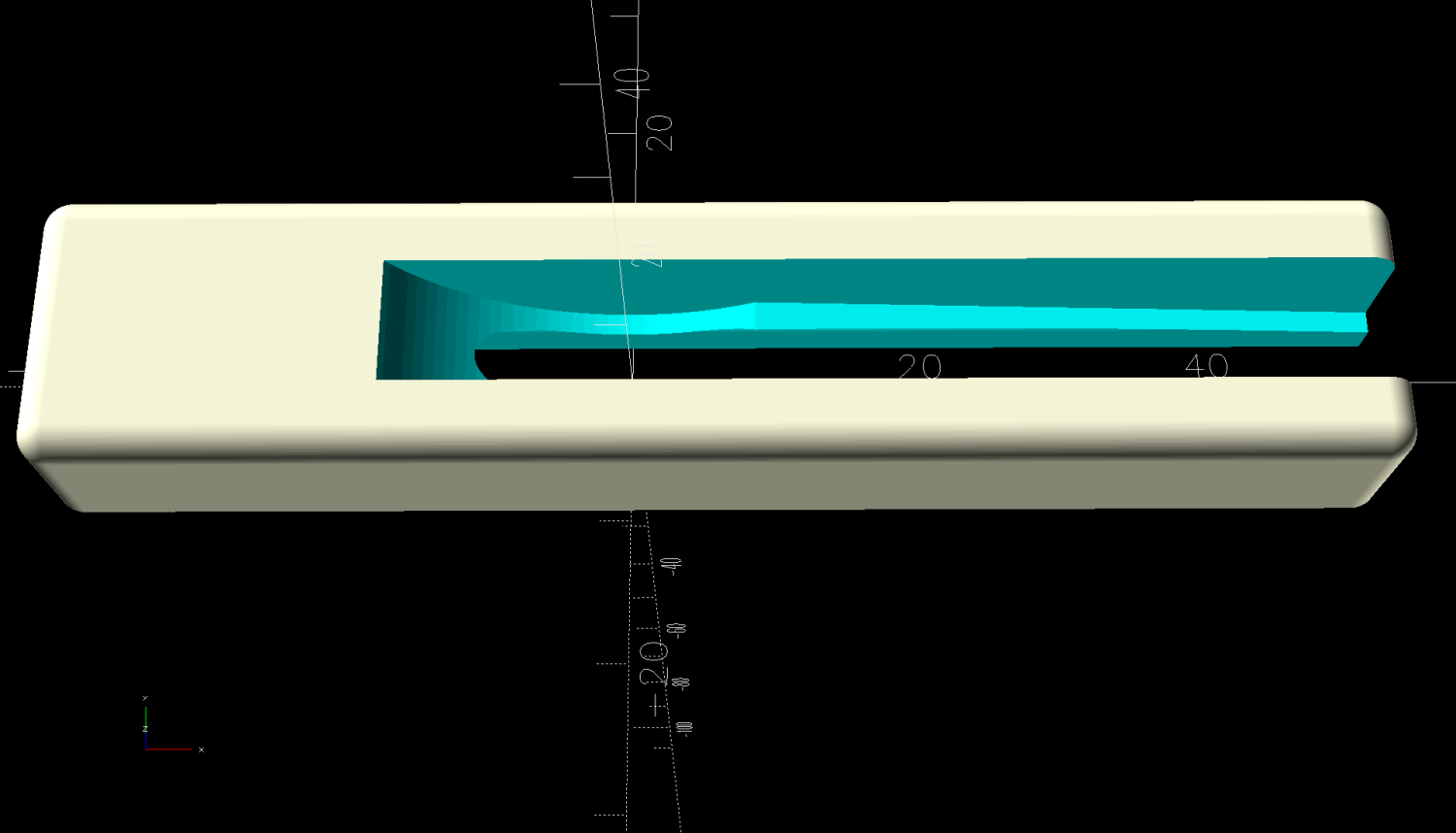
Do the same with a scan of the front face, import the curves into OpenSCAD, extrude them, create a solid model of the remote from their mutual intersection, then add a cylinder to punch the depression for the steel plate:
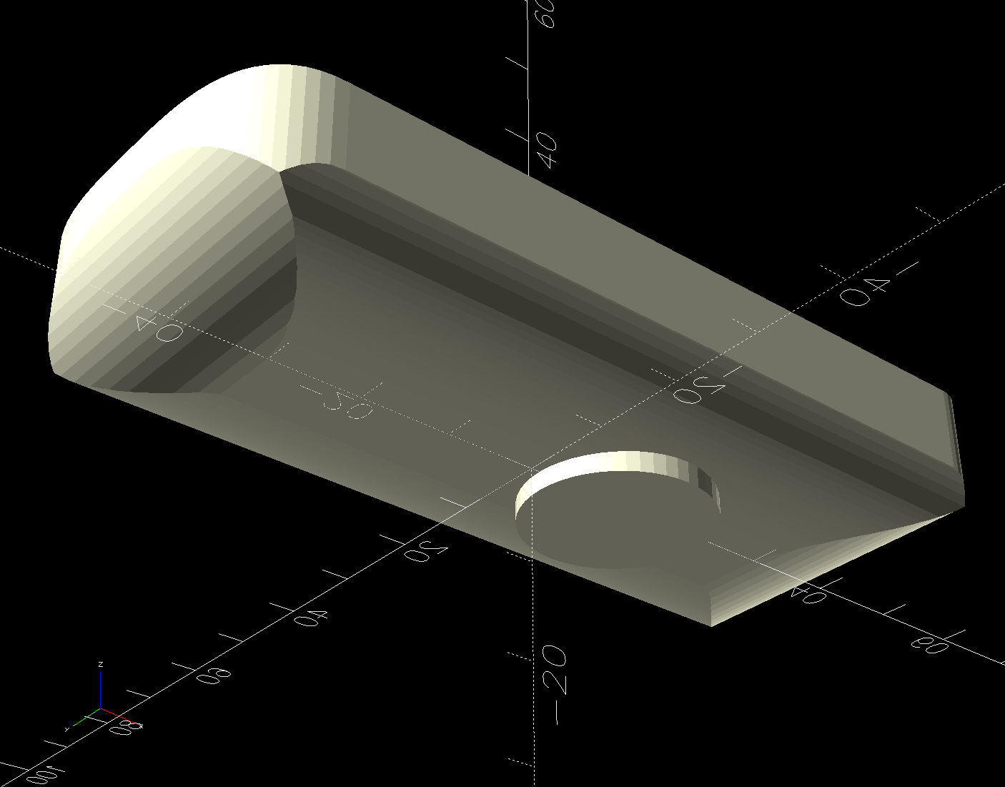
The chonky model corners stick out too far compared to the stylin’ curves on the real remote, but I made the holder shorter than the remote specifically to avoid fussing with such details.
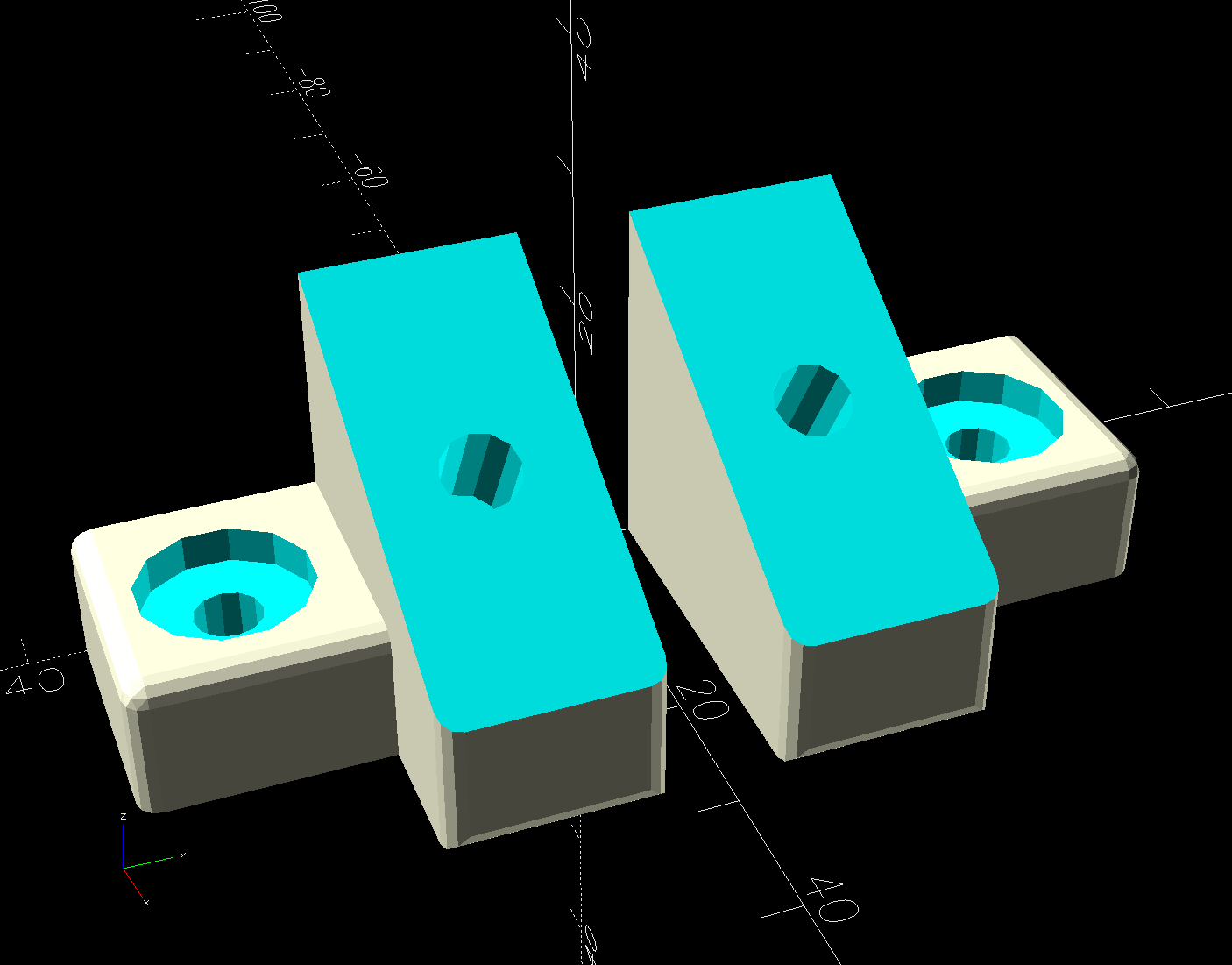
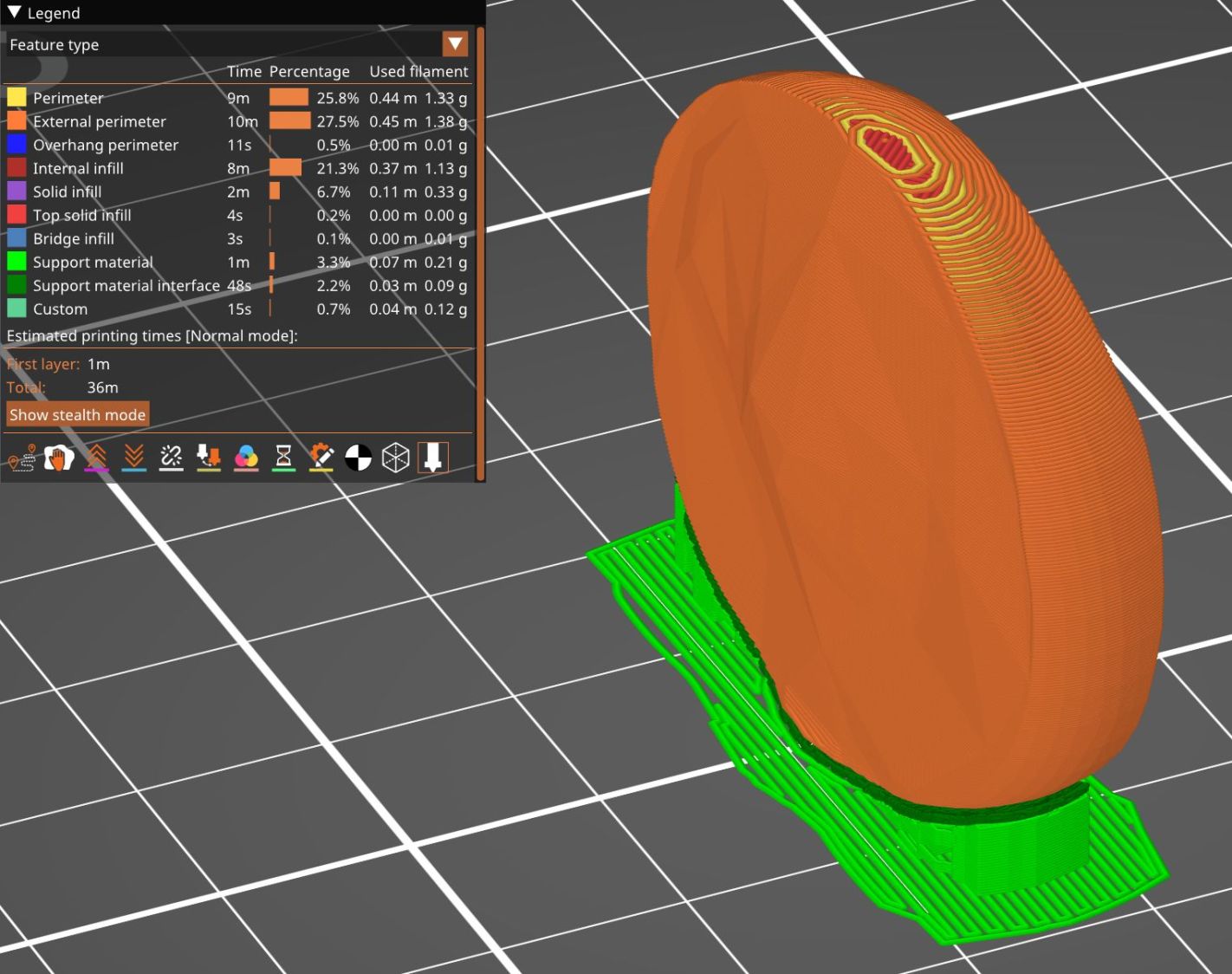
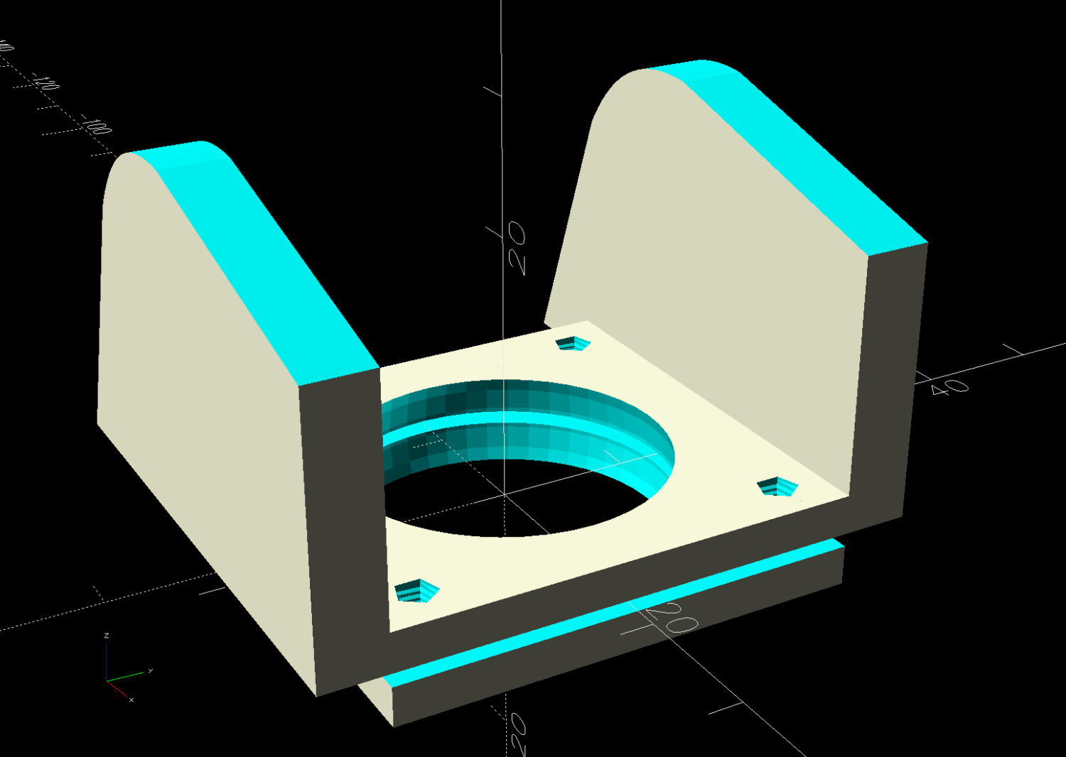
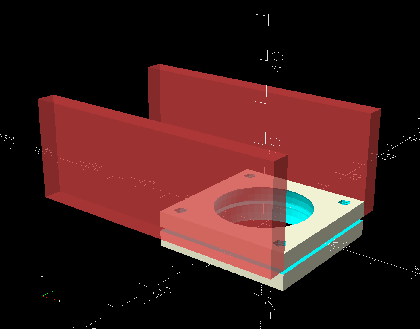
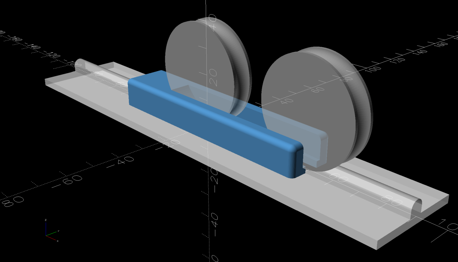
Subtract the remote from a nicely rounded cuboid and knock out a cylinder for the pipe it’ll mount on to produce the holder:

I briefly considered a circumferential clamp around the pipe before coming to my senses and making the pipe diameter 2 mm larger to accommodate a strip of double-sided foam tape.
The magnet gets a ferocious grip on the plate and I defined the result to be All Good™.
The OpenSCAD source code and SVG paths as a GitHub Gist:
| // Floor Lamp Remote Holder | |
| // Ed Nisley – KE4ZNU | |
| // 2025-03-29 | |
| include <BOSL2/std.scad> | |
| Layout = "Holder"; // [Show,Build,Remote,Holder] | |
| BaseAngle = 30; // [0:50] | |
| /* [Hidden] */ | |
| RemoteOA = [92.0,40.0,14.5]; | |
| PoleOD = 16.0; // lamp pole | |
| MagnetOD = 20.0; // steel plate under magnet | |
| MagnetOffset = [11.0,0,-2.0]; | |
| TapeThick = 1.2; | |
| HolderOA = [60.0,35.0,PoleOD/3 + 4.0 + RemoteOA.z/2]; | |
| HolderRadius = 5.0; | |
| Gap = 10.0; | |
| //———- | |
| // Define shapes | |
| module RemoteBody() { | |
| union() { | |
| intersection() { | |
| fwd(RemoteOA.y/2) up(RemoteOA.z/2) | |
| linear_extrude(h=RemoteOA.z,center=true) | |
| import("Floor Lamp Remote – outlines.svg",layer="Top Outline"); | |
| zrot(90) xrot(90) | |
| linear_extrude(h=RemoteOA.x,center=true) | |
| import("Floor Lamp Remote – outlines.svg",layer="End Outline"); | |
| xrot(90) | |
| linear_extrude(h=RemoteOA.y,center=true) | |
| import("Floor Lamp Remote – outlines.svg",layer="Side Outline"); | |
| } | |
| translate(MagnetOffset) | |
| cylinder(d=MagnetOD,h=RemoteOA.z,$fn=4*3*4); | |
| } | |
| } | |
| module Holder() { | |
| difference() { | |
| cuboid(HolderOA,anchor=BOTTOM,rounding=HolderRadius,except=TOP); | |
| down((PoleOD + 2*TapeThick)*(1/2 – 1/3)) | |
| yrot(90) | |
| cylinder(d=PoleOD + 2*TapeThick,h=2*HolderOA.x,center=true); | |
| up(HolderOA.z – RemoteOA.z/2) | |
| RemoteBody(); | |
| } | |
| } | |
| //———- | |
| // Build things | |
| if (Layout == "Remote") | |
| RemoteBody(); | |
| if (Layout == "Holder") | |
| Holder(); | |
| if (Layout == "Show") { | |
| color("White") | |
| Holder(); | |
| color("Gray",0.75) | |
| up(HolderOA.z – RemoteOA.z/2 + Gap) | |
| RemoteBody(); | |
| color("Green",0.5) | |
| down((PoleOD + 2*TapeThick)*(1/2 – 1/3)) | |
| yrot(90) | |
| cylinder(d=PoleOD + 2*TapeThick,h=2*HolderOA.x,center=true); | |
| } | |
| if (Layout == "Build") { | |
| Holder(); | |
| } | |


