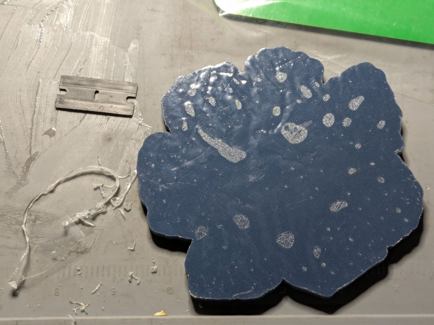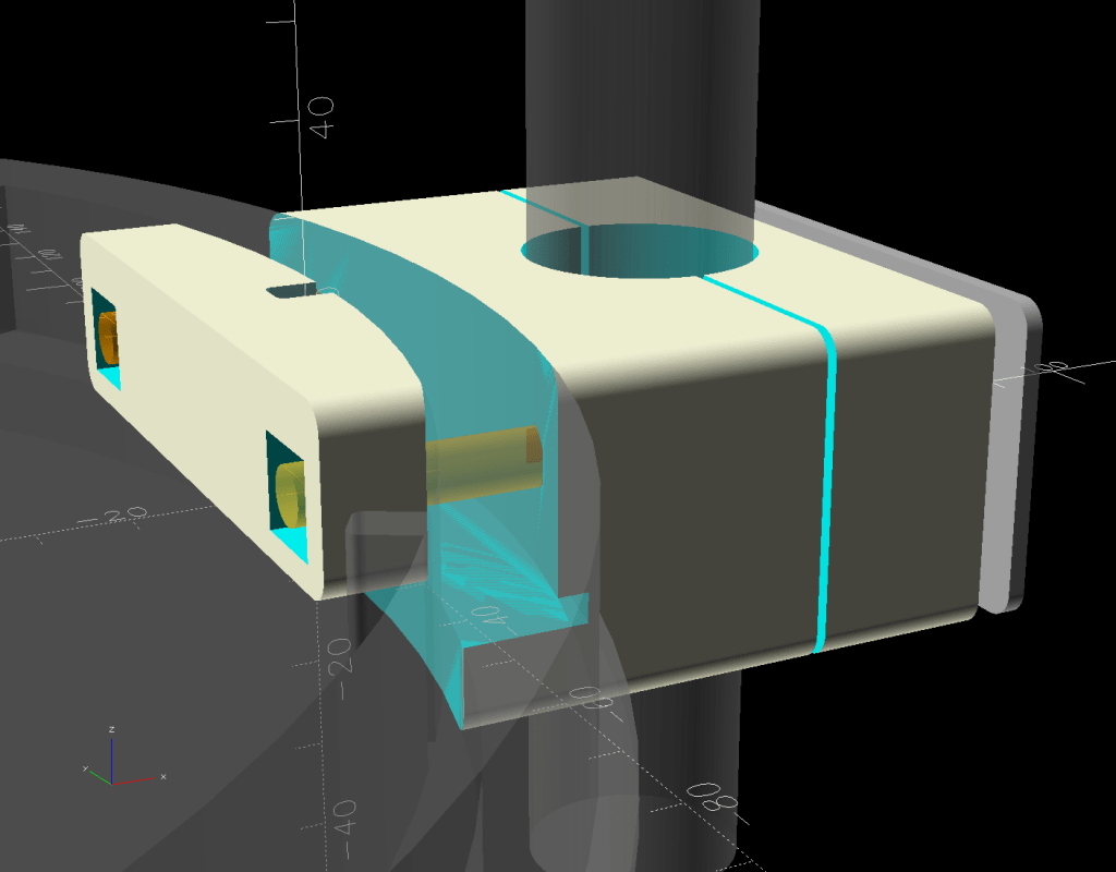
The mixed flock attending the bird feeder in the back yard scatters enough seeds to attract the deer, so I added a tray underneath to catch the overspray:
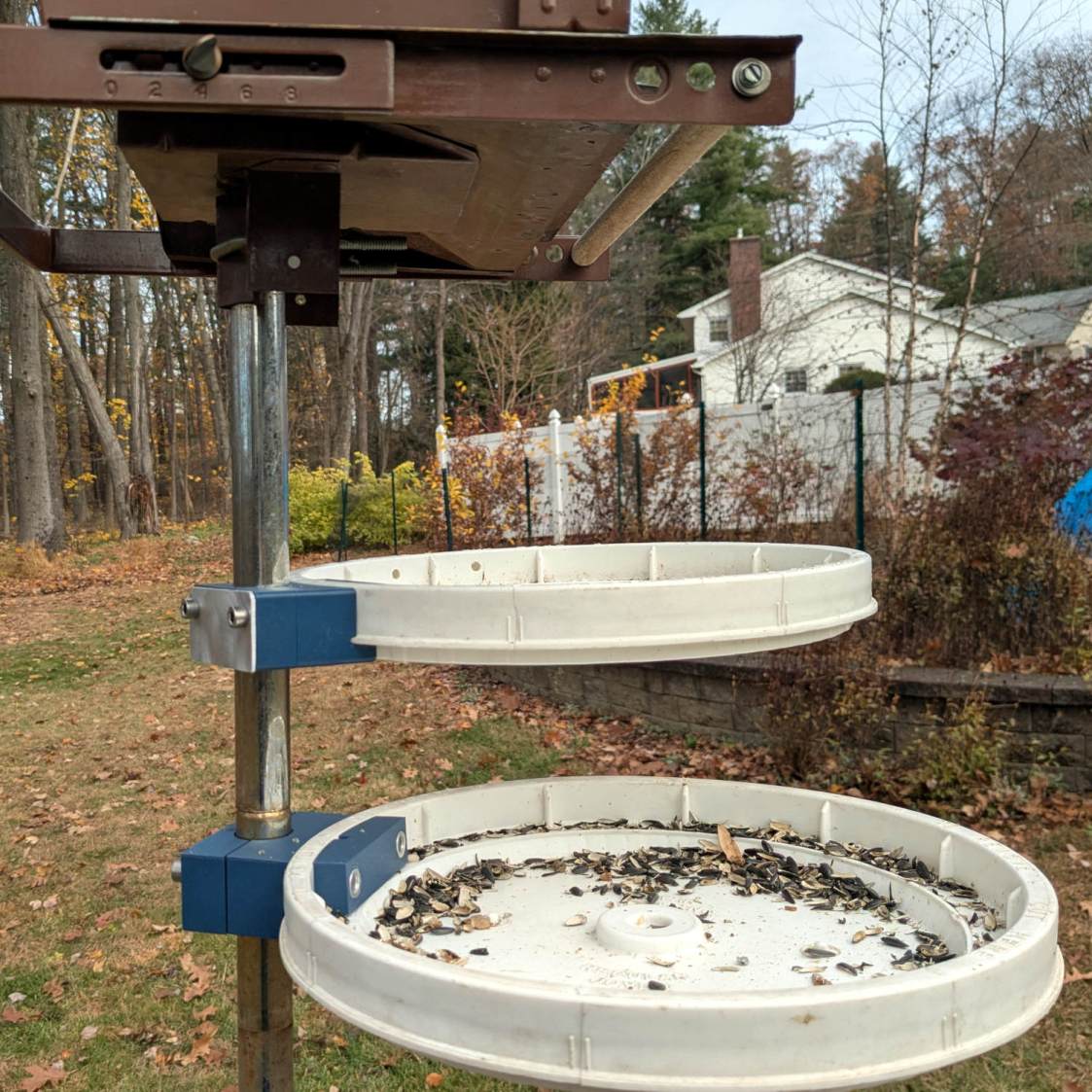
Well, two trays, because it took a couple of iterations to make the solid model match reality:
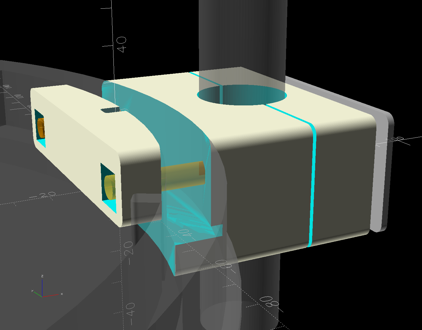
The n-1 iteration was Close Enough™ and two trays are obviously better than one.
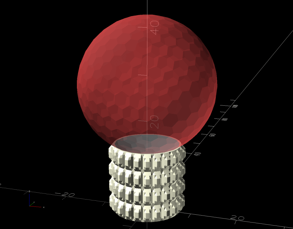
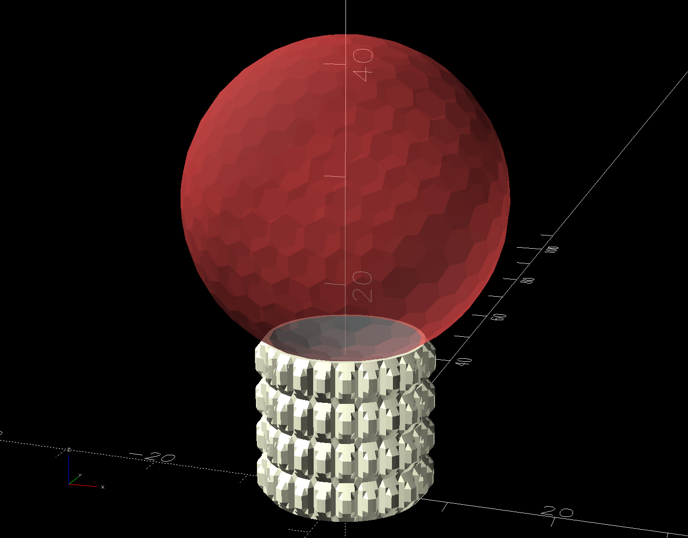
The “trays” are stray lids from the six gallon buckets we use for many purposes, including root-cellaring the vegetable garden harvest. The lid’s solid model was straightforward:
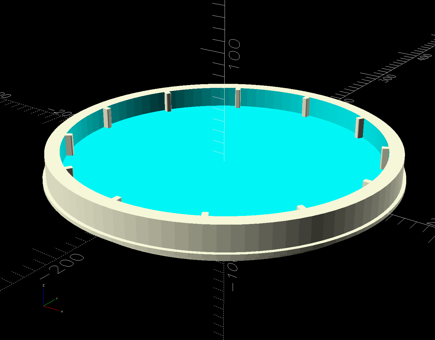
Removing the lid from a solid block produces the most complex part of the mount:
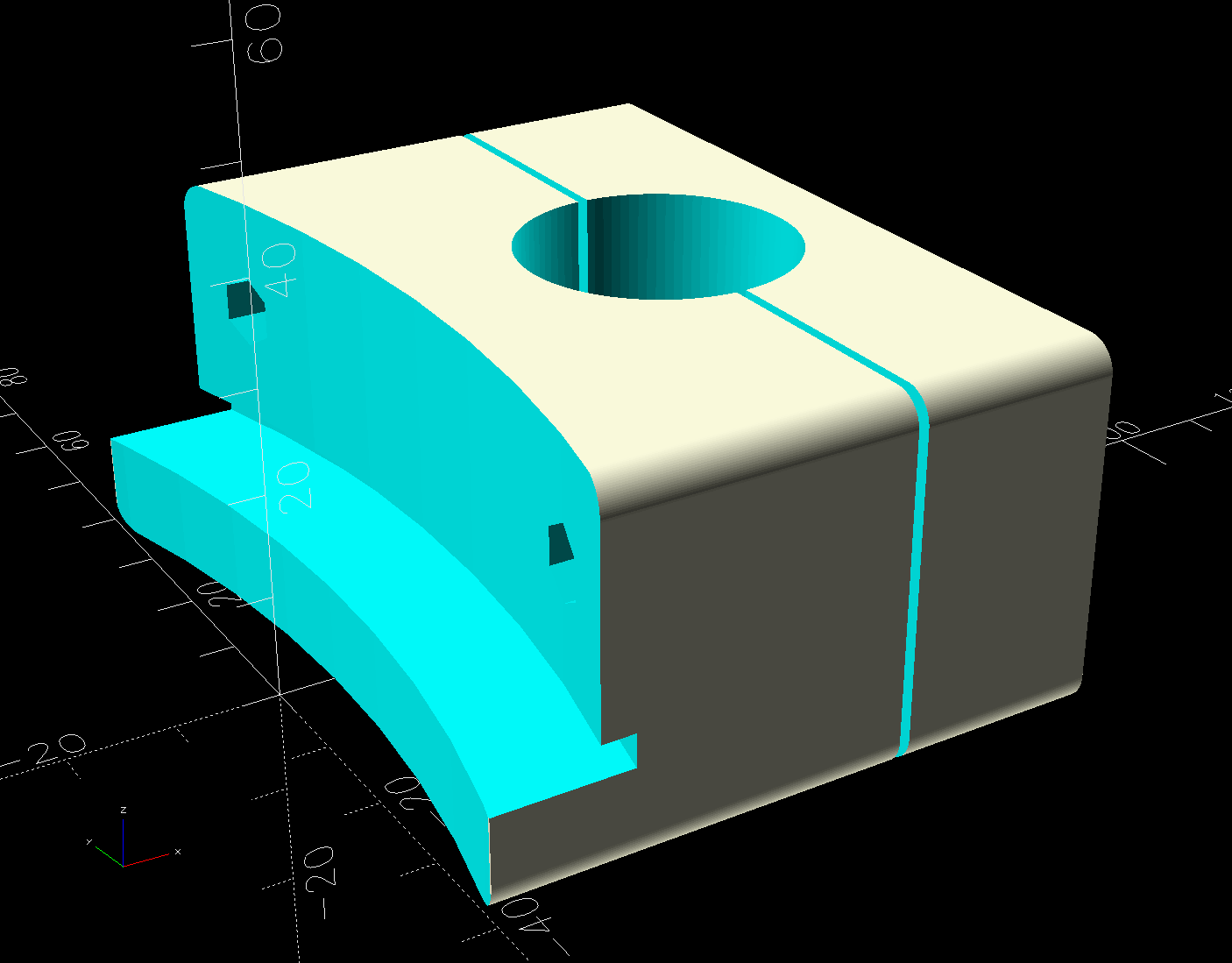
An aluminum plate on the outside (the gray slab in the overall view above) distributes the strain from the two M6 screws across the block.
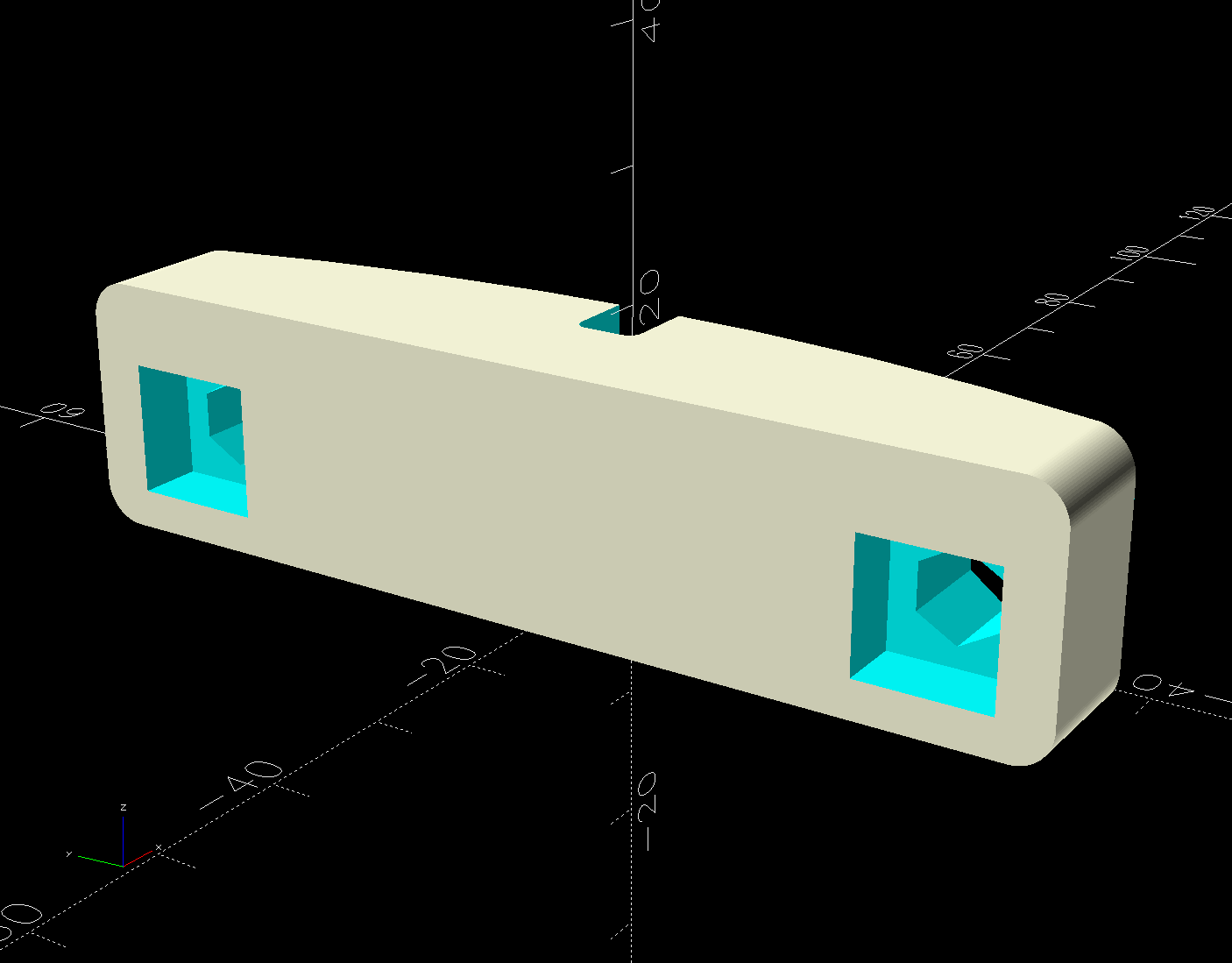
A smaller block on the inside of the lid has a pair of square nuts:
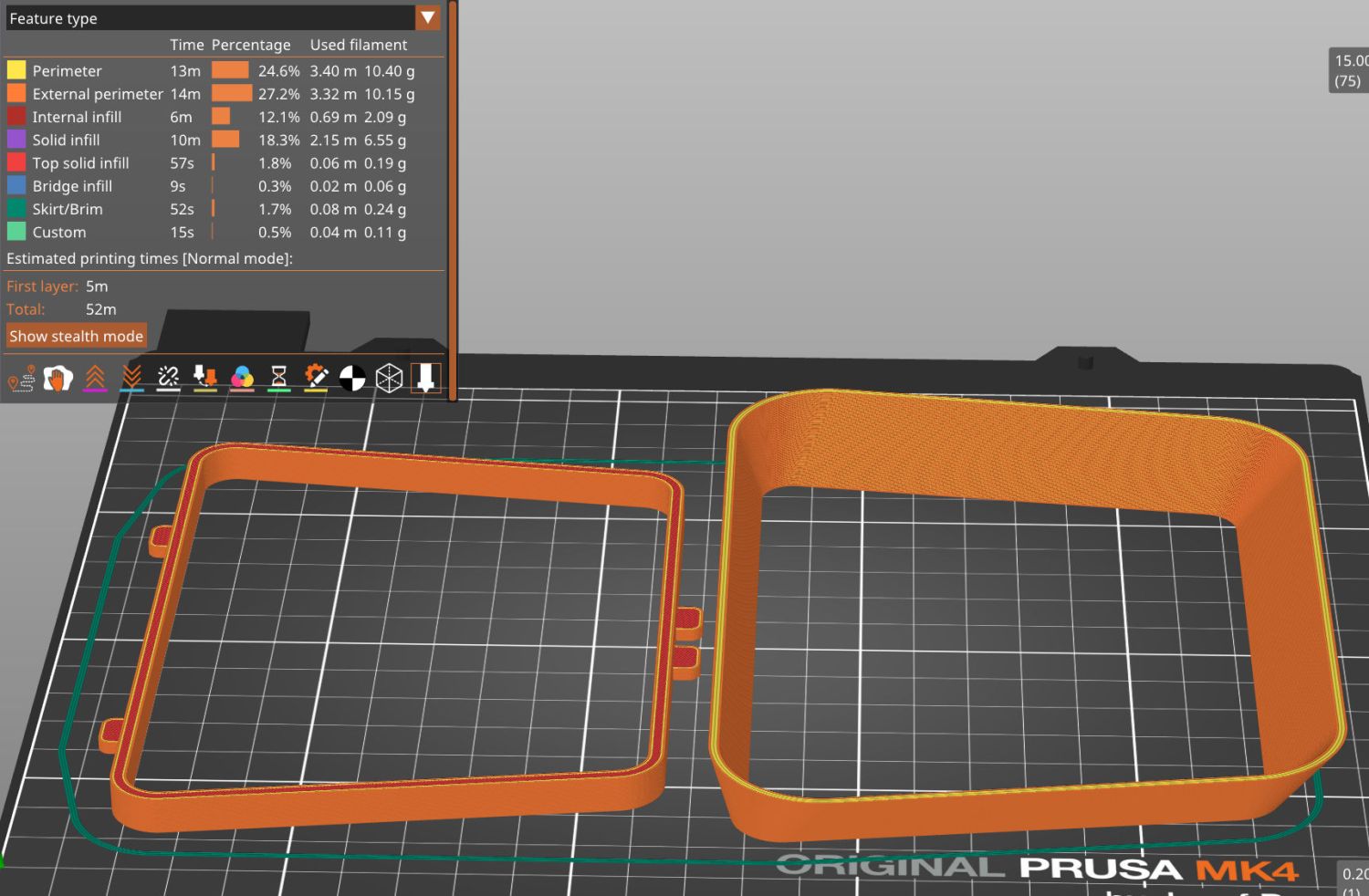
All three parts build from their flattest side:
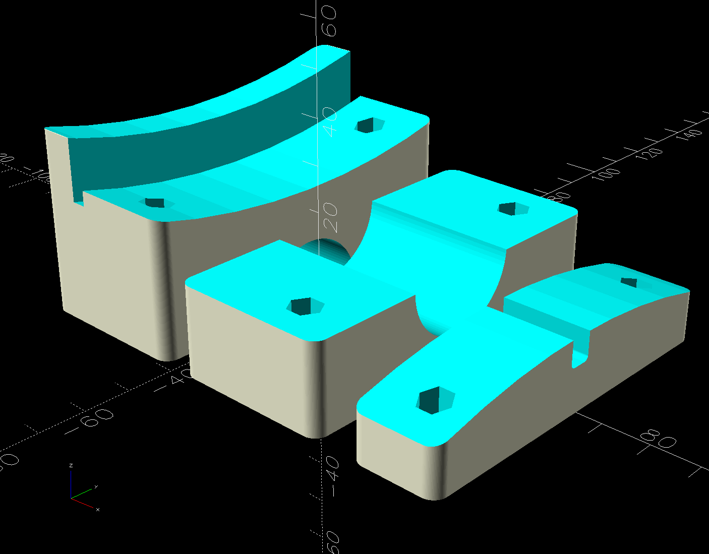
The downward facing clamp arch in the main block didn’t need support, but the square nut sockets in the segment definitely came out better with little support blocks inside; PrusaSlicer does a good job with most support structures.
The n-1 iteration used M6 rivnuts that were slightly too long after making the lid model match reality, so I switched to square nuts. The OpenSCAD code calculates the segment block length to match the actual screws, but 75 mm M6 screws and square nuts are barely long enough.
I clamped the outer block to the lid as a drill guide for the first hole, then pinned the block with a screw to ensure it didn’t slip while drilling the second hole:
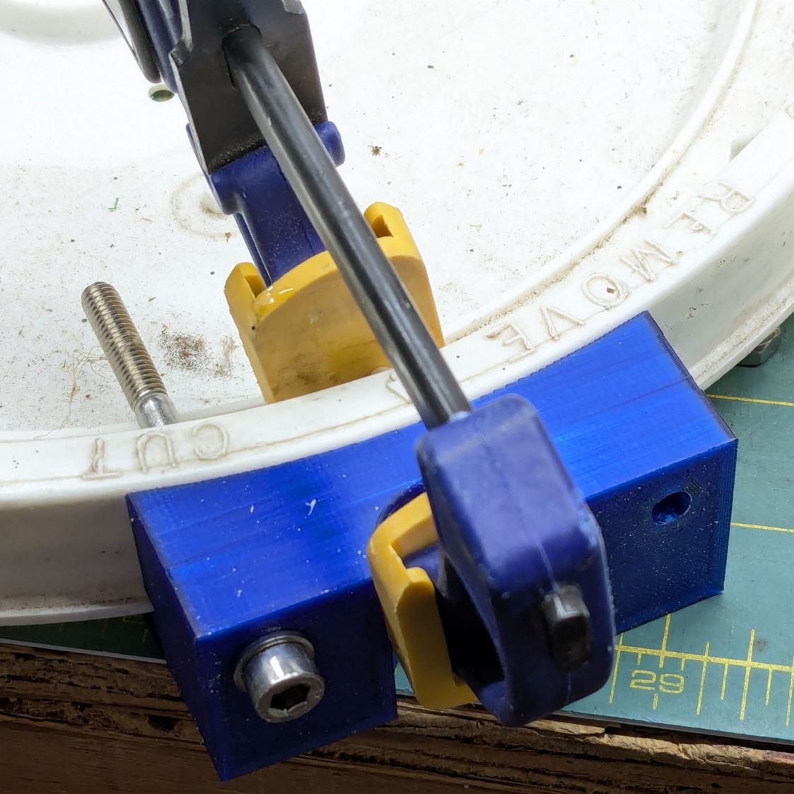
Those were freehanded in the drill press at low speed with serious concentration; some things you just gotta do that way.
The mixed flock overwhelmingly approves the trays, to the extent a dozen birds clamor to use them: definitely a crowd-pleaser!
I’m certain you can buy pole-mounted trays, but what’s the fun in that?
The OpenSCAD source code as a GitHub Gist:
| // Bird feeder tray mount | |
| // Ed Nisley – KE4ZNU | |
| // 2025-11-06 | |
| include <BOSL2/std.scad> | |
| Layout = "Show"; // [Build,Show,Lid,Mount,Segment,Nut] | |
| /* [Hidden] */ | |
| ID = 0; | |
| OD = 1; | |
| LENGTH = 2; | |
| HoleWindage = [0.2,0.2,0.2]; | |
| Protrusion = 0.1; | |
| NumRibs = 12; // stiffening ribs | |
| NumSides = 8*NumRibs; | |
| $fn=NumSides; | |
| Gap = 5.0; | |
| WallThick = 9.0; // robust walls | |
| Kerf = 1.0; // clamp cut | |
| TapeThick = 0.5; // wrap around pole | |
| LidOD = 12; // main diameter in inches | |
| PoleOD = 1*INCH; | |
| PlateThick = 2.0; // backing plate for clamp | |
| Screw = [6.0,12.0,6.0]; // thread OD, washerOD, head | |
| ScrewLength = 75.0; | |
| ScrewOC = 60.0; // chosen to clear stiffening ribs in lid | |
| LidLayers = [ // bottom to top, ID = 0 means solid disk, LENGTH = exterior measurement | |
| [0,(LidOD-2*(3/8))*INCH,Protrusion], // 0 – below zero to prevent Z fighting | |
| [0,(LidOD-2*(3/8))*INCH,(3/8)*INCH], // 1 – base inside bucket | |
| [0,(LidOD+2*(1/8))*INCH,(1/8)*INCH], // 2 – flange | |
| [(LidOD-2*(1/2))*INCH,LidOD*INCH,(7/8)*INCH], // 3 – sealing ring | |
| ]; | |
| LidOAH = LidLayers[1][LENGTH] + LidLayers[2][LENGTH] + LidLayers[3][LENGTH]; | |
| LidTopDepth = (3/4)*INCH; // from highest part of interior | |
| MountBlockWidth = ScrewOC + 2*WallThick; | |
| BaseSagitta = LidLayers[1][OD]/2 – sqrt((LidLayers[1][OD]/2)^2 – (MountBlockWidth^2)/4); | |
| echo(BaseSagitta=BaseSagitta); | |
| PoleOffset = BaseSagitta + ((LidLayers[2][OD] – LidLayers[1][OD])/2) + WallThick + PoleOD/2; | |
| MountBlock = [PoleOffset + PoleOD/2 + WallThick – PlateThick,MountBlockWidth,LidOAH]; | |
| echo(MountBlock=MountBlock); | |
| SegBlockOffset = ScrewLength – MountBlock.x – PlateThick; // assumes recessed | |
| SegmentBlock = [2*SegBlockOffset,MountBlock.y,LidTopDepth]; | |
| Rib = [2*6.0,5.0,LidTopDepth]; // lid stiffening ribs | |
| RibAlign = 0 * 180/NumRibs; // position ribs wrt mount | |
| EdgeRadius = 3.0; | |
| //—– | |
| // Rivnut | |
| // The model collects all the magic numbers right here | |
| /* | |
| RivnutOAL = 15.0; | |
| module Rivnut() { | |
| union() { | |
| cyl(1.6,d=13.0,circum=true,anchor=BOTTOM); | |
| cyl(RivnutOAL,d=9.0,circum=true,anchor=BOTTOM); | |
| } | |
| } | |
| */ | |
| //—– | |
| // Square nut | |
| // The model collects all the magic numbers right here | |
| NutOAL = 5.0; | |
| module SquareNut() { | |
| cuboid([10.0,10.0,5.0],anchor=BOTTOM); | |
| } | |
| //—– | |
| // Bucket lid | |
| // Centered at XY=0, Z=0 at top of exterior flange | |
| module BucketLid(Interior=true,Expand=false) { | |
| render() | |
| union() { | |
| down(LidLayers[2][LENGTH]) | |
| cyl(LidLayers[1][LENGTH],d=LidLayers[1][OD],anchor=TOP); | |
| cyl(LidLayers[2][LENGTH],d=LidLayers[2][OD],anchor=TOP); | |
| if (Interior) { | |
| if (false) | |
| down(Expand ? Protrusion : 0) | |
| tube(LidLayers[3][LENGTH] + (Expand ? 2*Protrusion : 0), | |
| id=LidLayers[3][ID],od=(Expand ? 2 : 1)*LidLayers[3][OD],anchor=BOTTOM); | |
| else | |
| difference() { | |
| cyl(LidLayers[3][LENGTH] + (Expand ? 2*Protrusion : 0), | |
| d=(Expand ? 2 : 1)*LidLayers[3][OD],anchor=BOTTOM); | |
| up(LidLayers[3][LENGTH] – LidTopDepth) | |
| cyl(LidTopDepth + (Expand ? 2*Protrusion : 0), | |
| d=LidLayers[3][ID],anchor=BOTTOM); | |
| } | |
| up(LidLayers[3][LENGTH] – LidTopDepth) | |
| for (i=[0:(NumRibs – 1)]) | |
| zrot(i*360/NumRibs + RibAlign) | |
| right(LidLayers[3][ID]/2) | |
| cuboid(Rib,anchor=BOTTOM,rounding=1,edges="Z"); | |
| } | |
| else | |
| down(Expand ? Protrusion : 0) | |
| cyl(LidLayers[3][LENGTH] + (Expand ? 2*Protrusion : 0), | |
| d=(Expand ? 2 : 1)*LidLayers[3][OD],anchor=BOTTOM); | |
| } | |
| } | |
| // Mount clamp | |
| module Mount() { | |
| render() | |
| difference() { | |
| cuboid(MountBlock,anchor=BOTTOM+LEFT,rounding=EdgeRadius,edges="X"); | |
| left(LidLayers[1][OD]/2 – BaseSagitta) | |
| up(LidLayers[1][LENGTH] + LidLayers[2][LENGTH]) | |
| BucketLid(Interior=false); | |
| right(PoleOffset) { | |
| cyl(3*MountBlock.z,d=(PoleOD + HoleWindage.x + 2*TapeThick),circum=true,anchor=CENTER); | |
| cuboid([Kerf,2*MountBlock.y,3*MountBlock.z]); | |
| } | |
| if (false) | |
| right(MountBlock.x – PlateThick) | |
| cuboid(3*[PlateThick,MountBlock.y,MountBlock.z],anchor=LEFT); | |
| up(LidOAH – LidLayers[3][LENGTH]/2) | |
| for (j=[-1,1]) | |
| fwd(j*ScrewOC/2) { | |
| cyl(ScrewLength,d=Screw[ID] + HoleWindage.x,circum=true,orient=RIGHT,anchor=BOTTOM,$fn=6,spin=180/6); | |
| if (false) | |
| right(MountBlock.x + Protrusion) | |
| cyl(Screw[LENGTH] + Protrusion,d=Screw[OD] + HoleWindage.x,circum=true, | |
| orient=LEFT,anchor=BOTTOM,$fn=12,spin=180/12); | |
| } | |
| } | |
| } | |
| // Nut block segment inside lid | |
| module NutSegment() { | |
| render() | |
| difference() { | |
| cuboid(SegmentBlock,anchor=BOTTOM,rounding=EdgeRadius,edges="X"); | |
| down(LidLayers[3][LENGTH] – LidTopDepth) | |
| left(LidLayers[1][OD]/2 – BaseSagitta) | |
| BucketLid(Interior=true,Expand=true); | |
| up(LidTopDepth – LidLayers[3][LENGTH]/2) | |
| for (j=[-1,1]) | |
| fwd(j*ScrewOC/2) { | |
| left(SegmentBlock.x/2) | |
| cyl(ScrewLength,d=Screw[ID],circum=true,anchor=BOTTOM,$fn=6,spin=180/6,orient=RIGHT); | |
| left(SegmentBlock.x/2) | |
| yrot(90) | |
| SquareNut(); | |
| } | |
| } | |
| } | |
| //—– | |
| // Build things | |
| if (Layout == "Lid") | |
| BucketLid(); | |
| if (Layout == "Mount") | |
| Mount(); | |
| if (Layout == "Segment") | |
| NutSegment(); | |
| if (Layout == "Nut") | |
| Rivnut(); | |
| if (Layout == "Show") { | |
| down(LidLayers[1][LENGTH] + LidLayers[2][LENGTH]) { | |
| Mount(); | |
| color("Orange",0.5) | |
| up(LidOAH – LidLayers[3][LENGTH]/2) | |
| right(MountBlock.x + PlateThick) | |
| for (j=[-1,1]) | |
| fwd(j*ScrewOC/2) | |
| cyl(ScrewLength,d=Screw[ID],circum=true,orient=LEFT,anchor=BOTTOM); | |
| } | |
| up(LidLayers[3][LENGTH] – LidTopDepth) | |
| NutSegment(); | |
| color("Gray",0.4) | |
| right(PoleOffset) | |
| cylinder(3*MountBlock.z,d=(PoleOD),anchor=CENTER); | |
| color("Gray",0.4) | |
| left(LidLayers[1][OD]/2 – BaseSagitta) | |
| BucketLid(); | |
| color("White",0.7) | |
| down(LidLayers[1][LENGTH] + LidLayers[2][LENGTH]) | |
| right(MountBlock.x + 2*PlateThick) | |
| difference() { | |
| cuboid([PlateThick,MountBlock.y,MountBlock.z],anchor=BOTTOM+LEFT,rounding=EdgeRadius,edges="X"); | |
| up(LidOAH – LidLayers[3][LENGTH]/2) | |
| for (j=[-1,1]) | |
| fwd(j*ScrewOC/2) | |
| cyl(ScrewLength,d=Screw[ID],circum=true,orient=RIGHT,anchor=CENTER); | |
| } | |
| } | |
| if (Layout == "Build") { | |
| render() | |
| union() { | |
| difference() { | |
| left(MountBlock.z + Gap/2) | |
| up(PoleOffset – Kerf/2) | |
| yrot(90) | |
| Mount(); | |
| cuboid([3*MountBlock.z,2*MountBlock.y,3*MountBlock.x],anchor=TOP); | |
| } | |
| render() | |
| right(Gap/2) | |
| intersection() { | |
| up(MountBlock.x) | |
| yrot(90) | |
| Mount(); | |
| up(MountBlock.x – PoleOffset) | |
| right(MountBlock.z/2) | |
| cuboid([2*MountBlock.z,2*MountBlock.y,MountBlock.x],anchor=TOP); | |
| } | |
| right(2*MountBlock.z – BaseSagitta) | |
| up(SegmentBlock.x/2) | |
| yrot(-90) | |
| NutSegment(); | |
| } | |
| } |