The Basement Shop has 50±5% relative humidity, with the top held down by a hulking dehumidifier (plus a box fan stirring the air) and the bottom supported by being a basement. As a result, the 3D printer filament stabilized at about 50% RH, which seemed to work well enough for PETG.
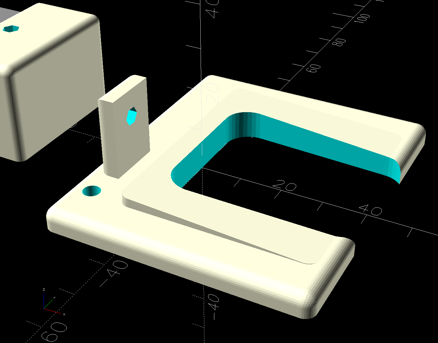
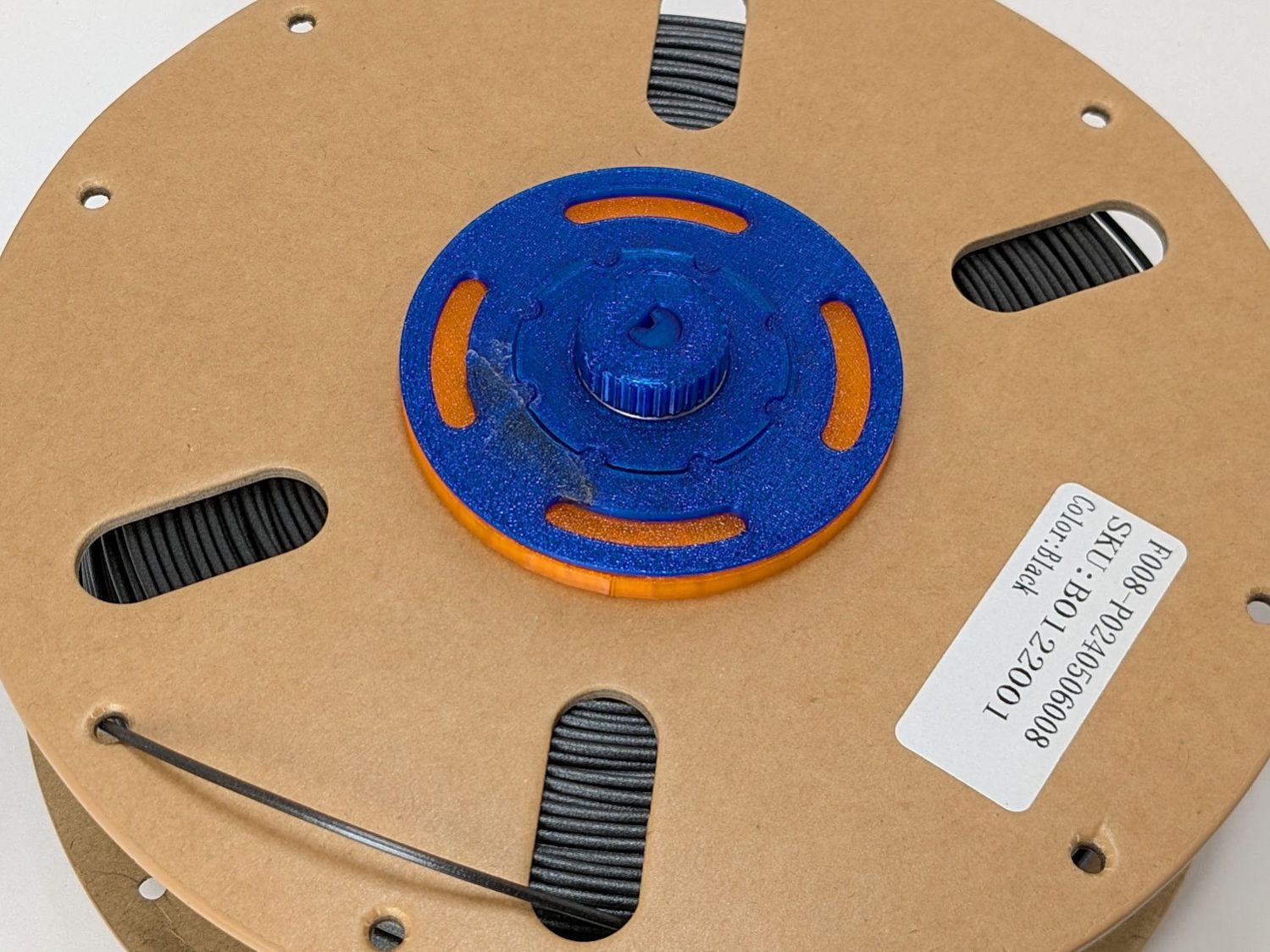
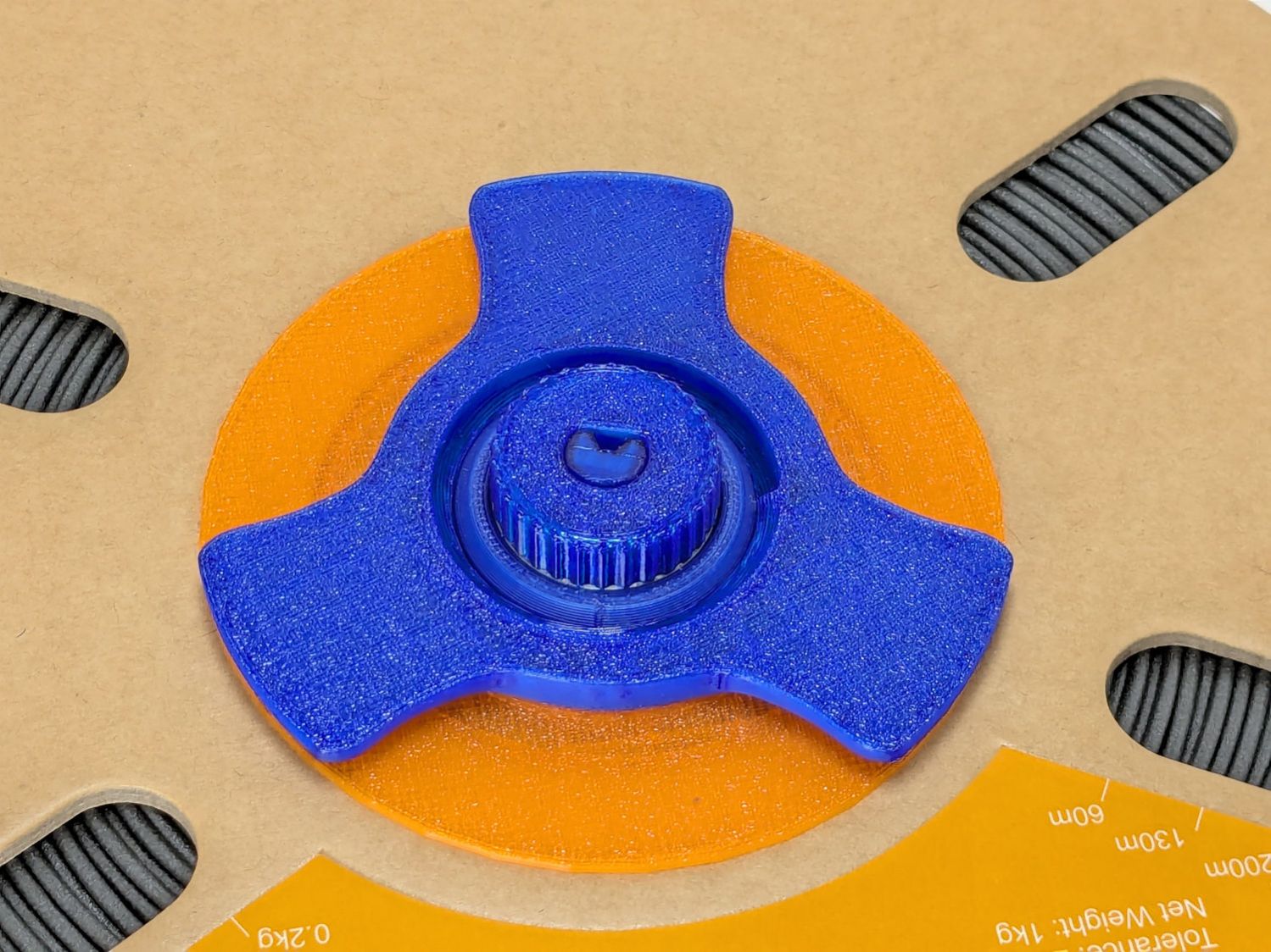
Adding TPU to the stable called for better humidity control, so I set up a bunch of PolyMaker PolyDryer boxes with Auto-rewind spindles.
After a few weeks, though, I didn’t expect this:

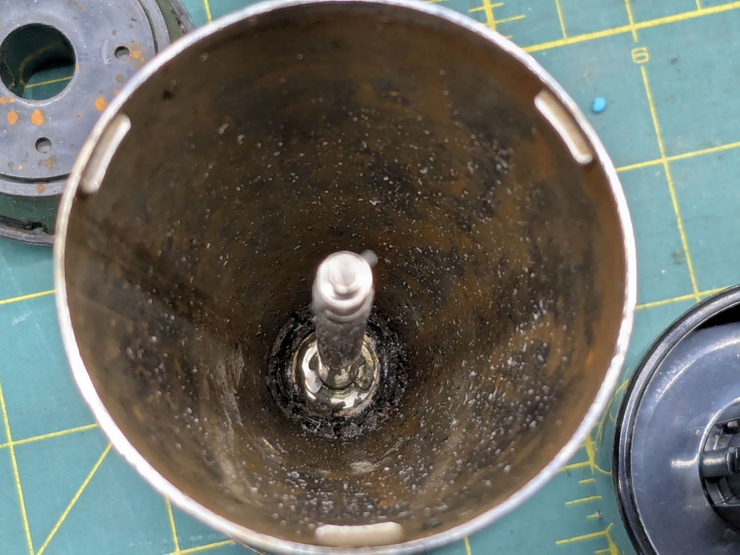
That’s activated alumina desiccant, mostly because it’s reputed to have more capacity and a lower ultimate humidity than silica gel, but it likely doesn’t make much difference.
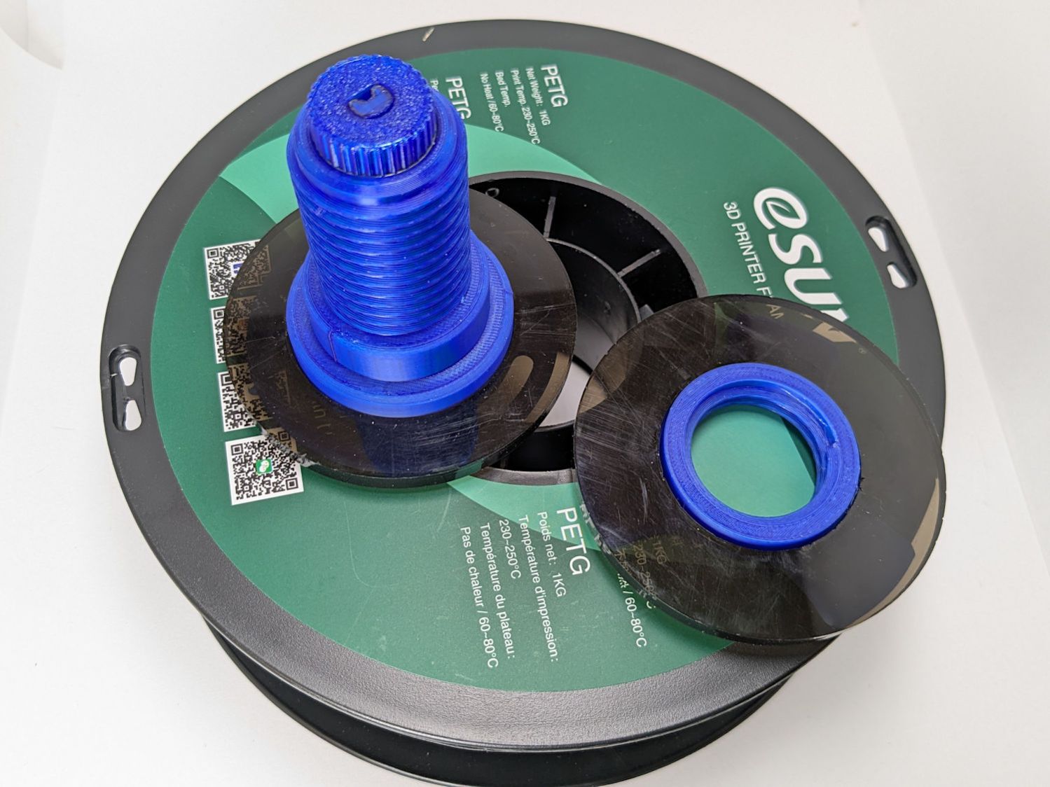
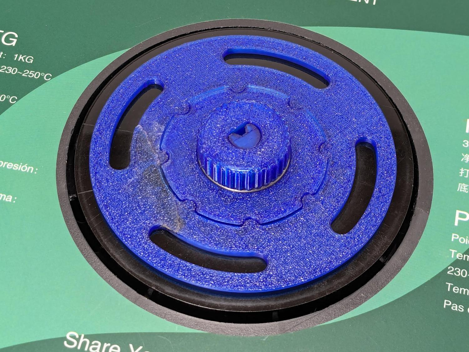
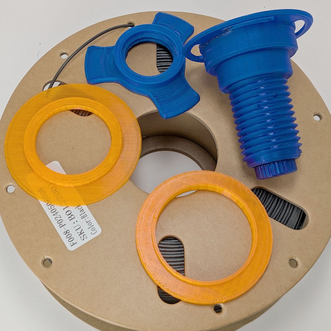
In addition to 25 g of desiccant in the PolyDryer meter case, I dropped five teabags holding 10 g each in the bottom of the box for more capacity. I measure the desiccant by putting 75.0 g into a cup, putting 25.0 g in the PolyDryer meter box (aided by a Polydryer Desiccant Funnel), 10.0 g into four teabags, and whatever’s left into the fifth teabag, thus eliminating rounding errors in the smaller quantities.
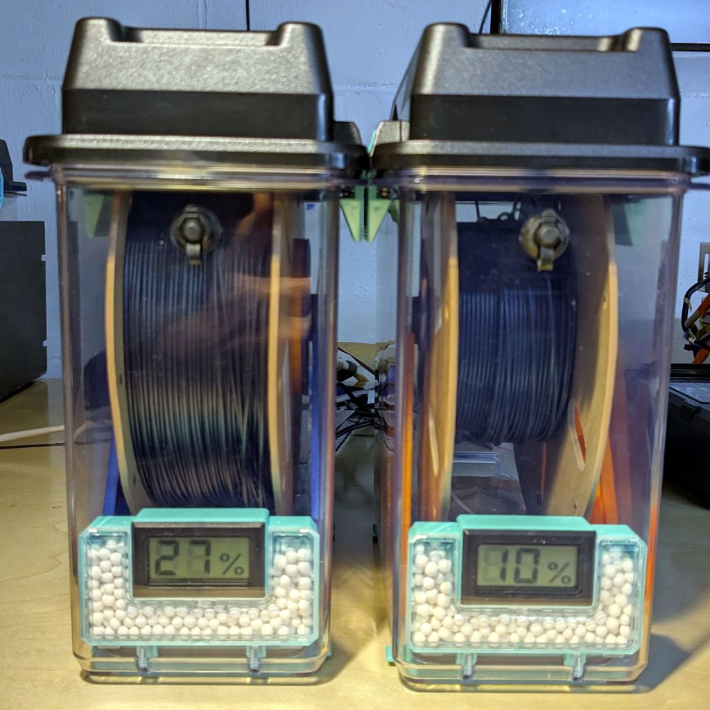
The stabilized humidity inside the boxes seems to depend on the amount of filament on the spool:
- Nearly full → 25% to 30% RH
- Half full → 20%-ish RH
- Nearly empty → 10% to 15% RH
I think the humidity level comes from the filament outgassing water vapor through its (limited) surface area on the outer layer around the spool. The difference between that rate and the desiccant’s ability to remove water vapor from the (unmoving) air in the box sets the stable humidity: more surface area → more water vapor → higher humidity.
After the filament eventually dries out, the humidity should decrease, but diffusion is a slow process. More likely, the humidity will remain stable as the printer pulls filament from the outer layer and exposes the somewhat wetter plastic within.
The heater and fan inside the PolyDryer base unit circulates hot air through the box around the spool, but depends on the desiccant to remove water vapor. Running the base unit for 6 or 12 hours makes little difference in the stabilized humidity, so I think the desiccant is doing the best it can as the filament outgasses more water vapor.
Using Air Exchanger vents seems to make no difference, likely because the desiccant must then pull more water vapor out of the incoming 50% RH basement air. A psychrometric chart says 50% RH air at 60 °F becomes 10% RH air at 120 °F, but moisture in the filament wrapped around the spool can’t escape any faster.
So, for example, a full spool of TPU starting at 25% RH:
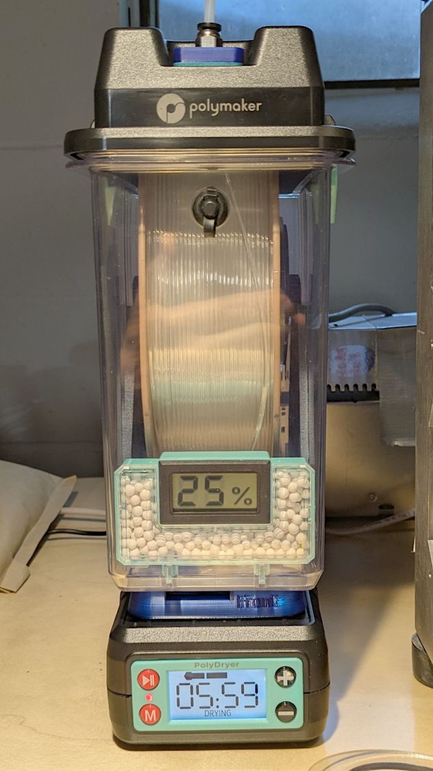
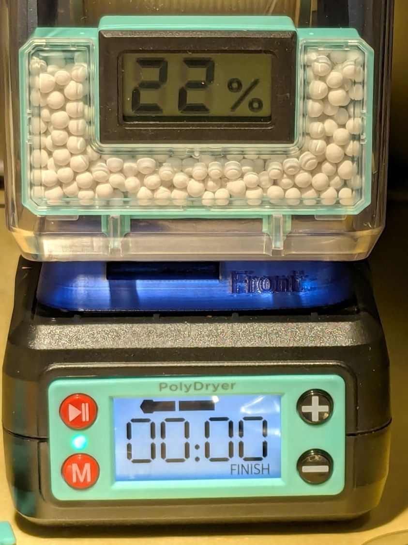
Six hours of drying pulls it down to 22%:
After sitting overnight it’s back at 25%:
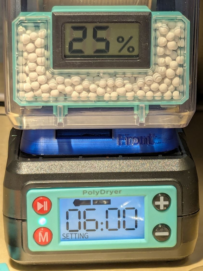
Admittedly, that was with the vents in place, but the closed box started at 25% RH after sitting around for a week or so following a similar drying cycle.
The desiccant had absorbed 4 g of water since I put it in, so it hasn’t been entirely idle.
Which suggests 75 g of activated alumina desiccant is workin’ hard and doin’ swell in there, with the filament acting as an essentially infinite reservoir of water vapor.
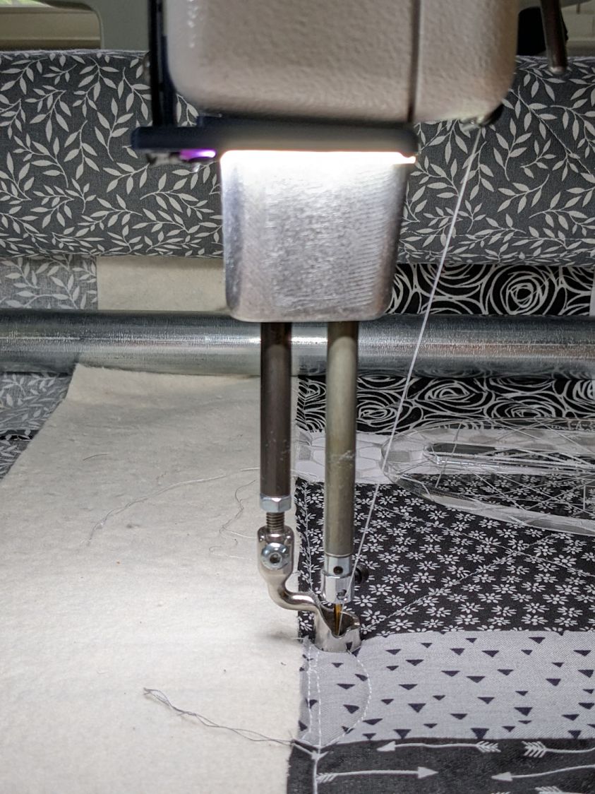
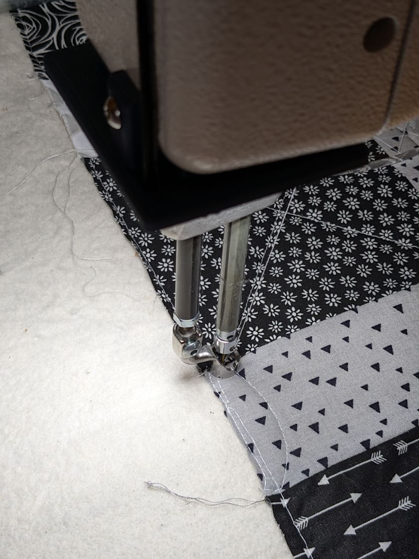
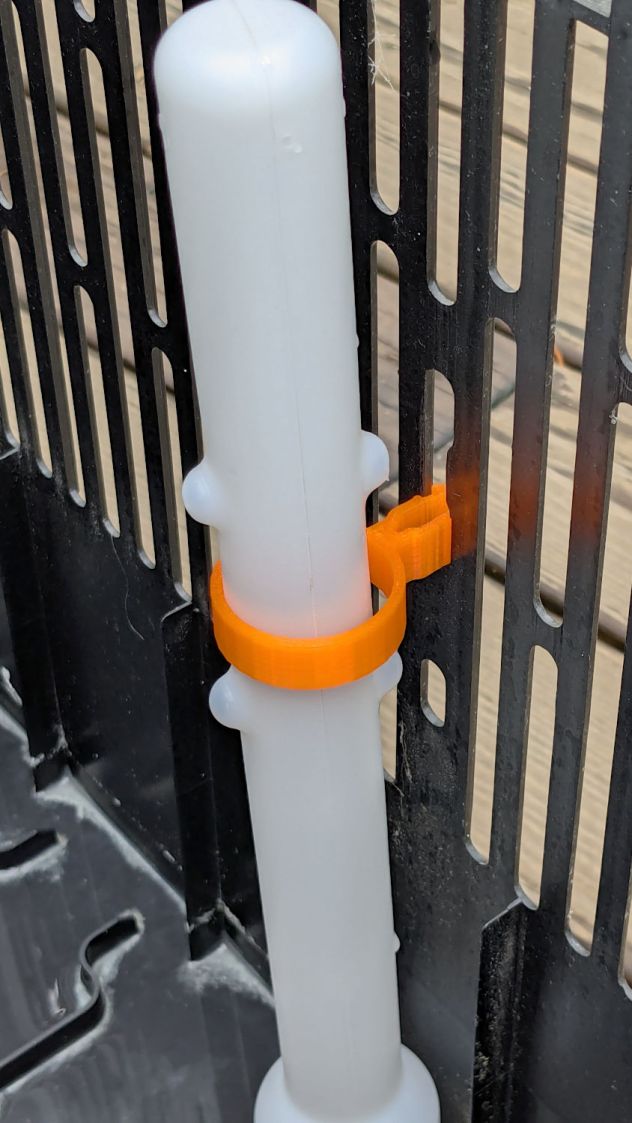
I haven’t noticed any particular difference in PETG print quality and the TPU hasn’t gotten enough mileage to notice much trouble, but reducing the MMU3 buffer clutter was totally worth the effort.


