Ed Nisley's Blog: Shop notes, electronics, firmware, machinery, 3D printing, laser cuttery, and curiosities. Contents: 100% human thinking, 0% AI slop.
The latches holding the side cover of the portable generator in place work well enough that I never tighten the cover screws, but sometimes one will vibrate itself into place and require less than one turn of a screwdriver to release. Given that I put a knob on the air filter screw, a pair of knobs on the side cover screws makes sense:
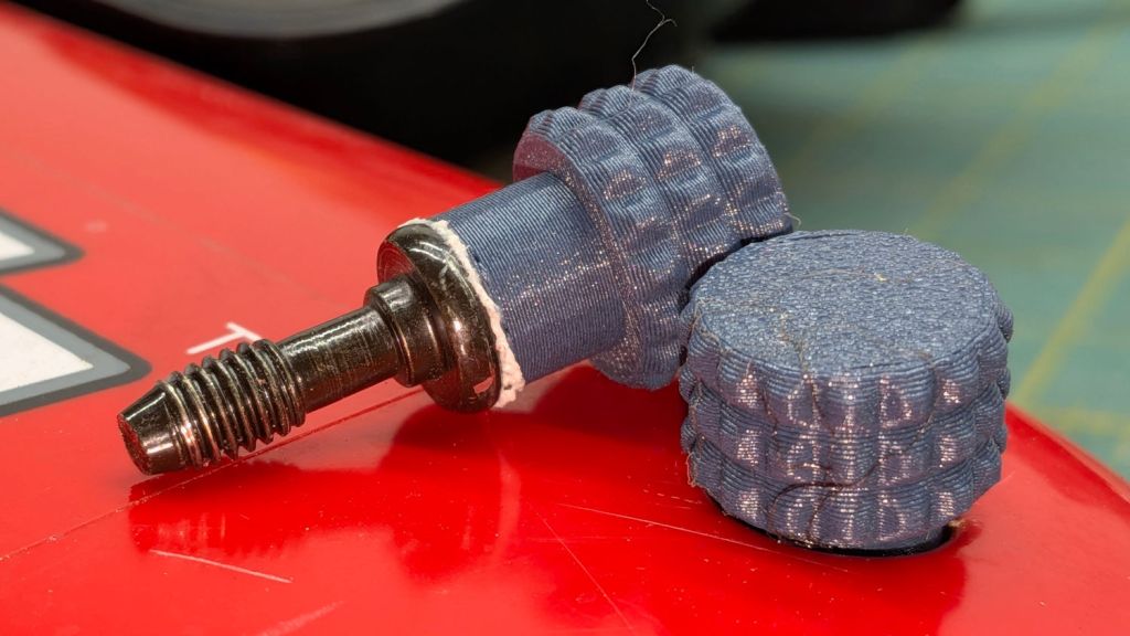
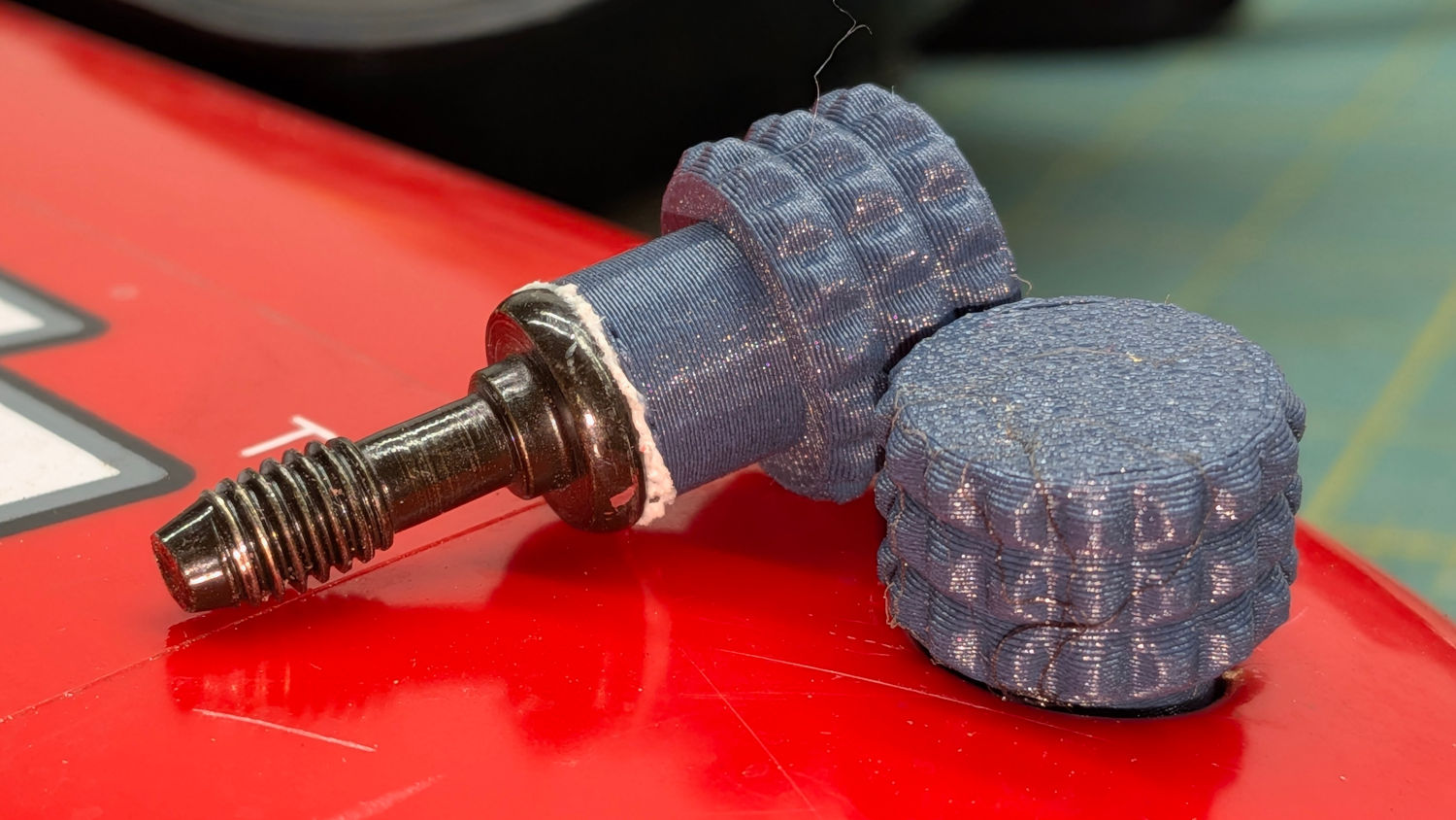
Generator Cover Screw Knob – installed
Those are custom screws! The narrow neck keeps them captive in the cover, which is a Good Thing™.
These knobs obviously descend from the air filter knob, with less knurling and a short shaft to clear the recess in the cover:
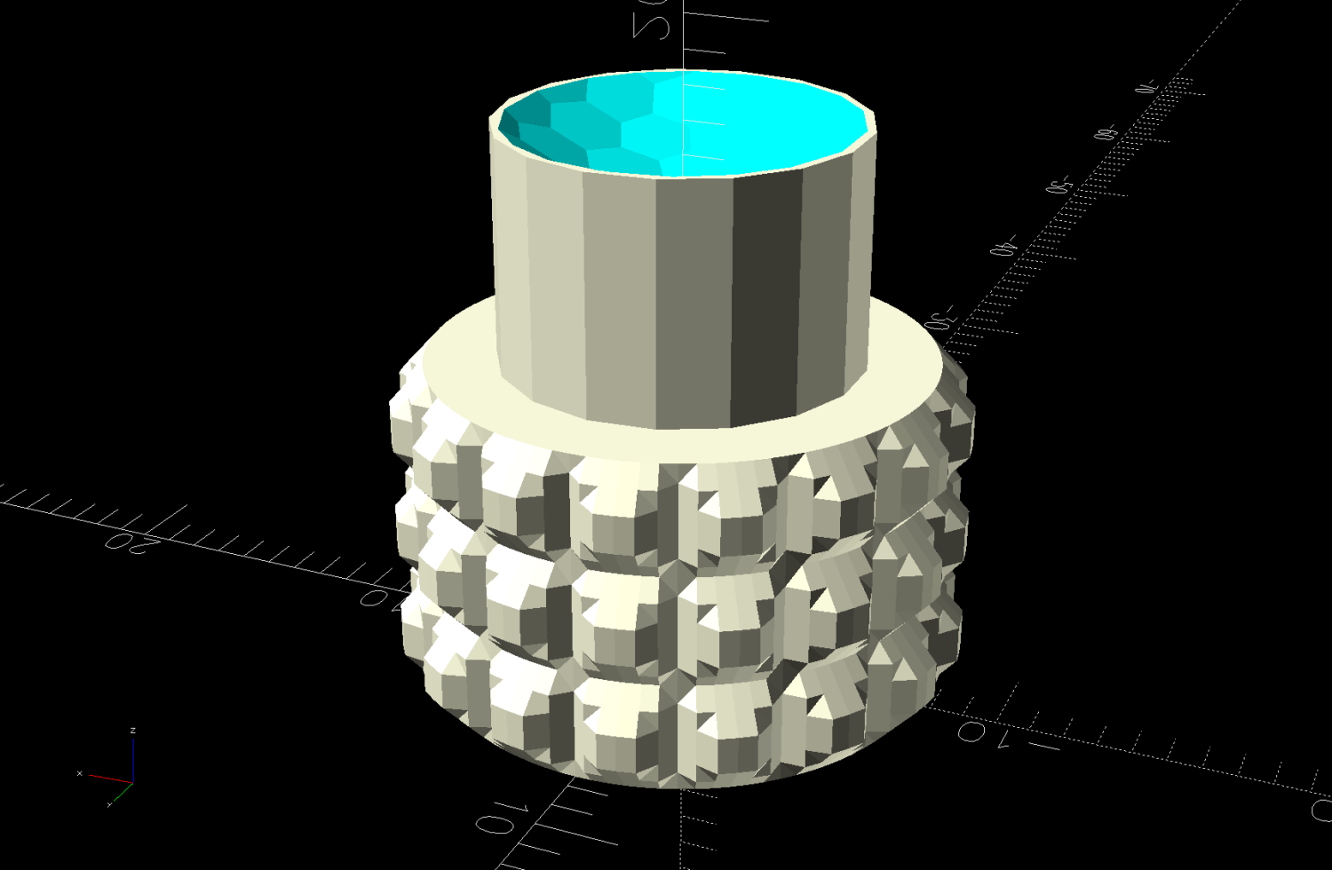
Generator Cover Screw Knob – solid model
Unlike the air filter knob, the double-sided tape gluing these to their screws isn’t continually compressed, so the knobs may eventually shake off. Should that happen, I’ll deploy epoxy.
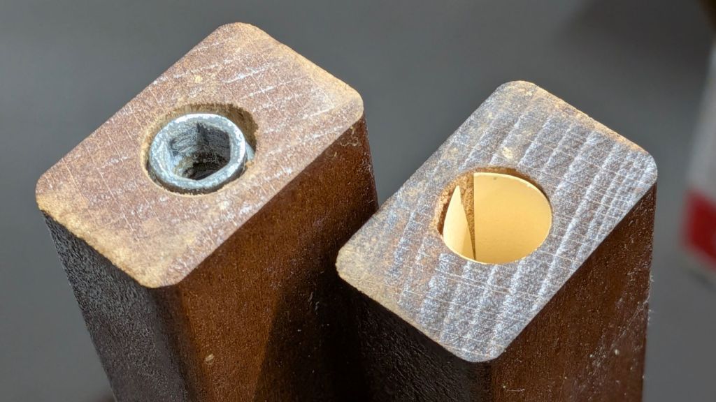
A clothes rack Mary intended use with some work-in-progress quilts seemed entirely too wobbly for the purpose, so I tried tightening its screws. This did not go well, as some of the threaded inserts sunk into the vertical bars spun freely and, with a bit of persuasion, pulled straight out of their sockets:
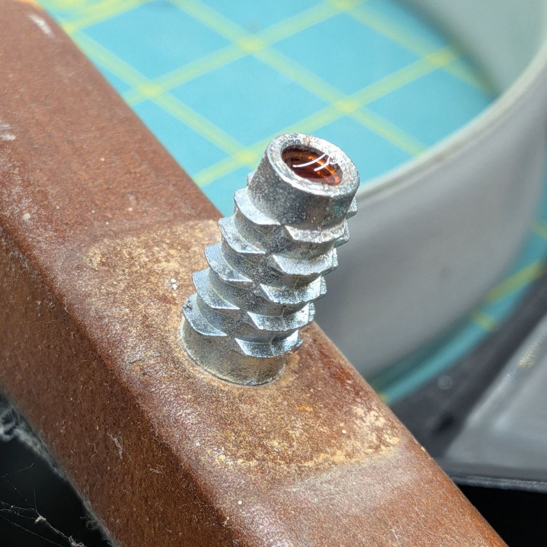
The reddish fluid is Kroil penetrating oil I hoped would free the screws from the corrosion locking them into the inserts. After an overnight soak, they still required force majeure:
Clothes rack screws – threaded insert in vise
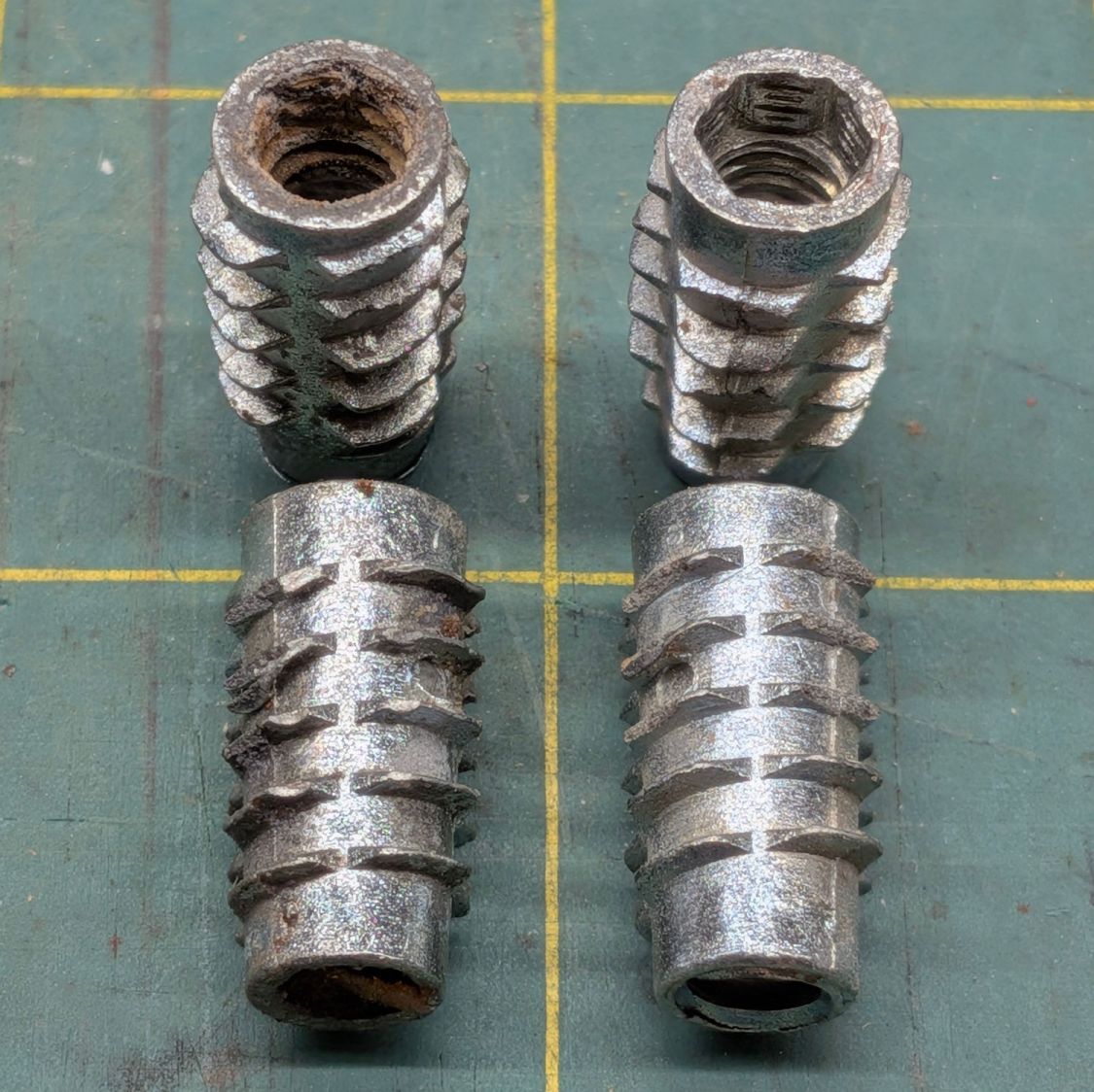
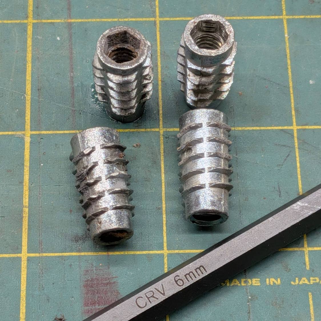
The two inserts on the left came from the top of the rack and the other two from the bottom:
Clothes rack screws – threaded insert corrosion
Similar inserts have a hex drive recess and, because these are for 1/4-20 screws, I expected an inch size hex key. Nope, they want a hard metric 6 mm:
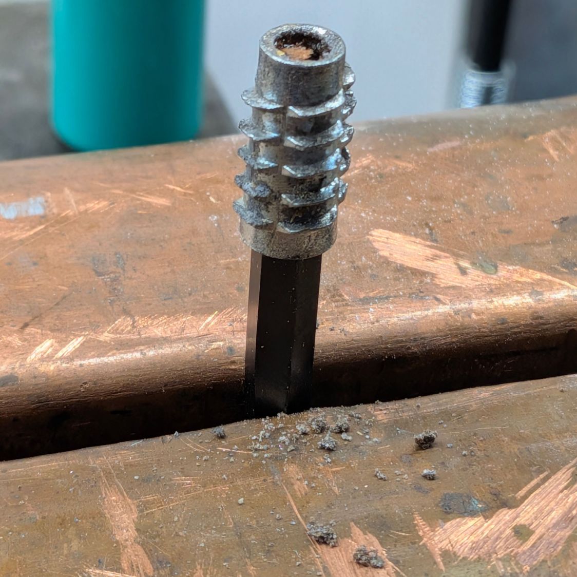
Clothes rack screws – threaded insert reformed
I cleaned up the corroded inserts by the simple expedient of tapping them firmly onto the 6 mm wrench held in the vise:
The crud around the bottom fell out of previous contestants during their reformation.
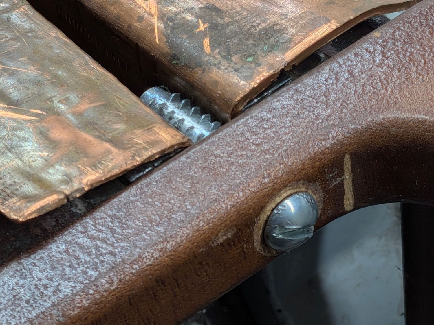
I considered epoxying the inserts in place, but settled for tucking a thick paper shim into each hole:
Clothes rack screws – threaded insert shim
They’re entirely snug right now and, should they work loose, I’ll coat the hole with epoxy, roll up another shim, screw the insert in place, await curing, then declare victory and hope nobody must ever remove them.
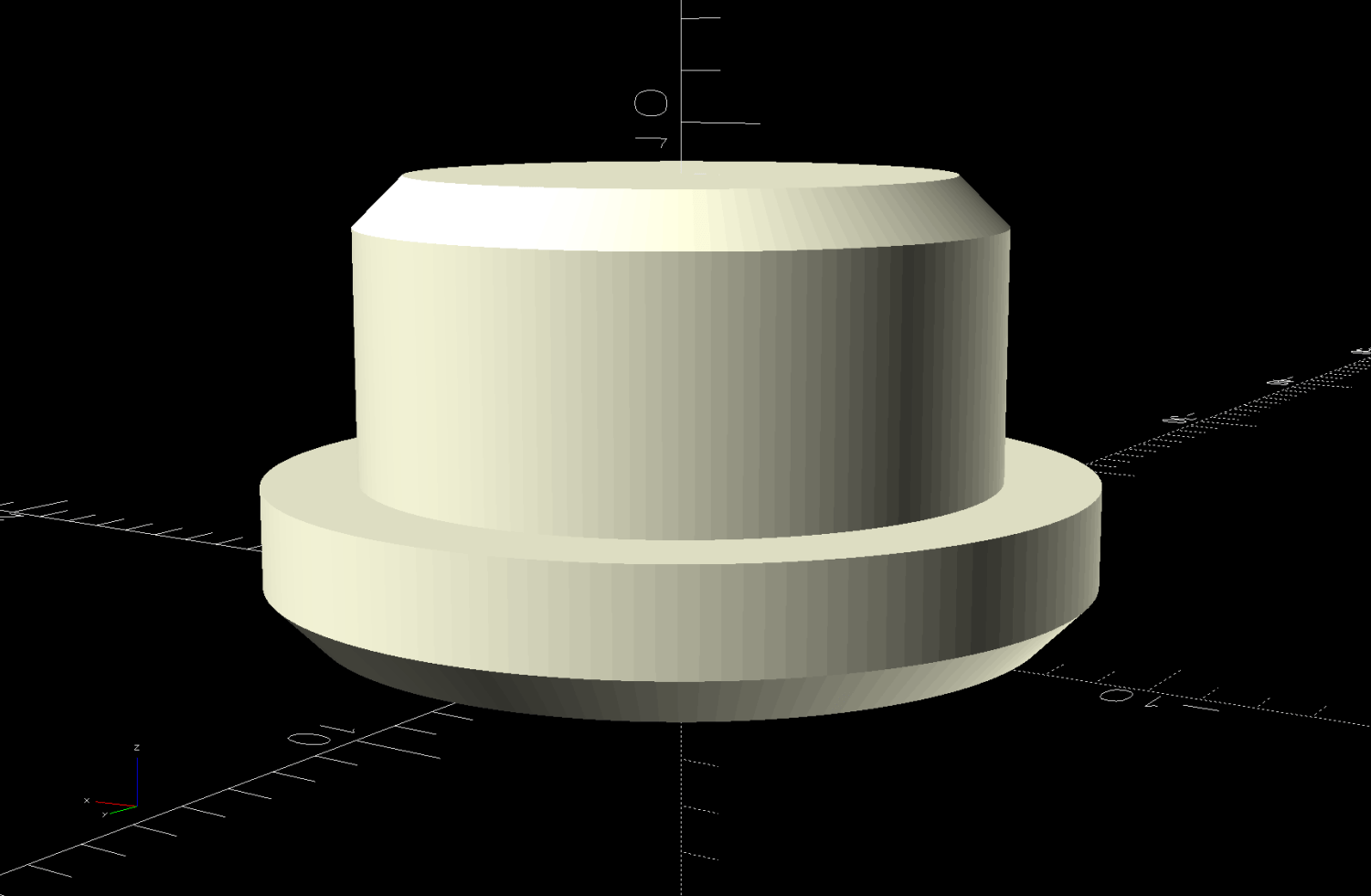
The 1/4-20 screws in the top member sit deep in recesses that surely had decorative wood plugs when the rack left the factory. Alas, they’re long gone, which may have let water / moisture corrode the screws + inserts . I’m not much good for “decorative” items, so this must suffice:
Clothes Rack Screw Covers – solid model
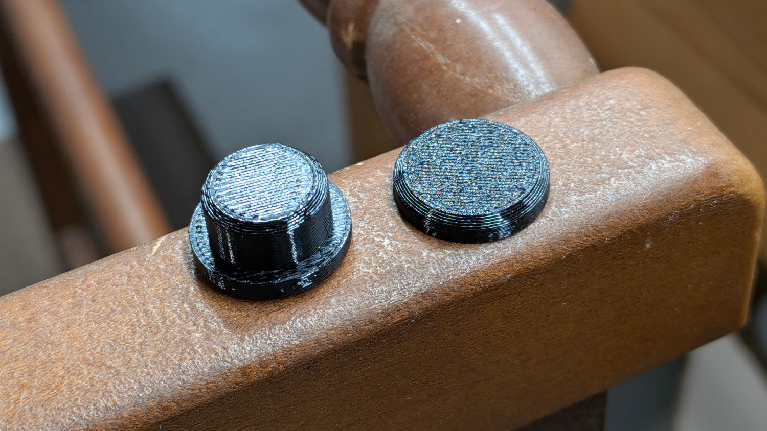
A snippet of double-sided tape on one side of the hole keeps them in place:
Clothes rack screws – cover installed
They look better in person …
The trivial OpenSCAD source code:
// Clothes rack screw cover
// Ed Nisley - KE4ZNU
// 2026-03-13

include <BOSL2/std.scad>

/* [Hidden] */

NumSides = 4*3*3*4;
$fn=NumSides;

//----------
// Build it
//  … with magic numbers from the rack

cyl(3.0,d=16.7,chamfer1=1.0,anchor=BOTTOM) position(TOP)
  cyl(6.0,d=12.9,chamfer2=1.0,anchor=BOTTOM);
The 3D printed Clover Mini-Iron holder served well over the last decade (!), even after one of Mary’s buddies misplaced the iron during a quilting bee:
Clover MCI-900 Mini Iron holder – melted
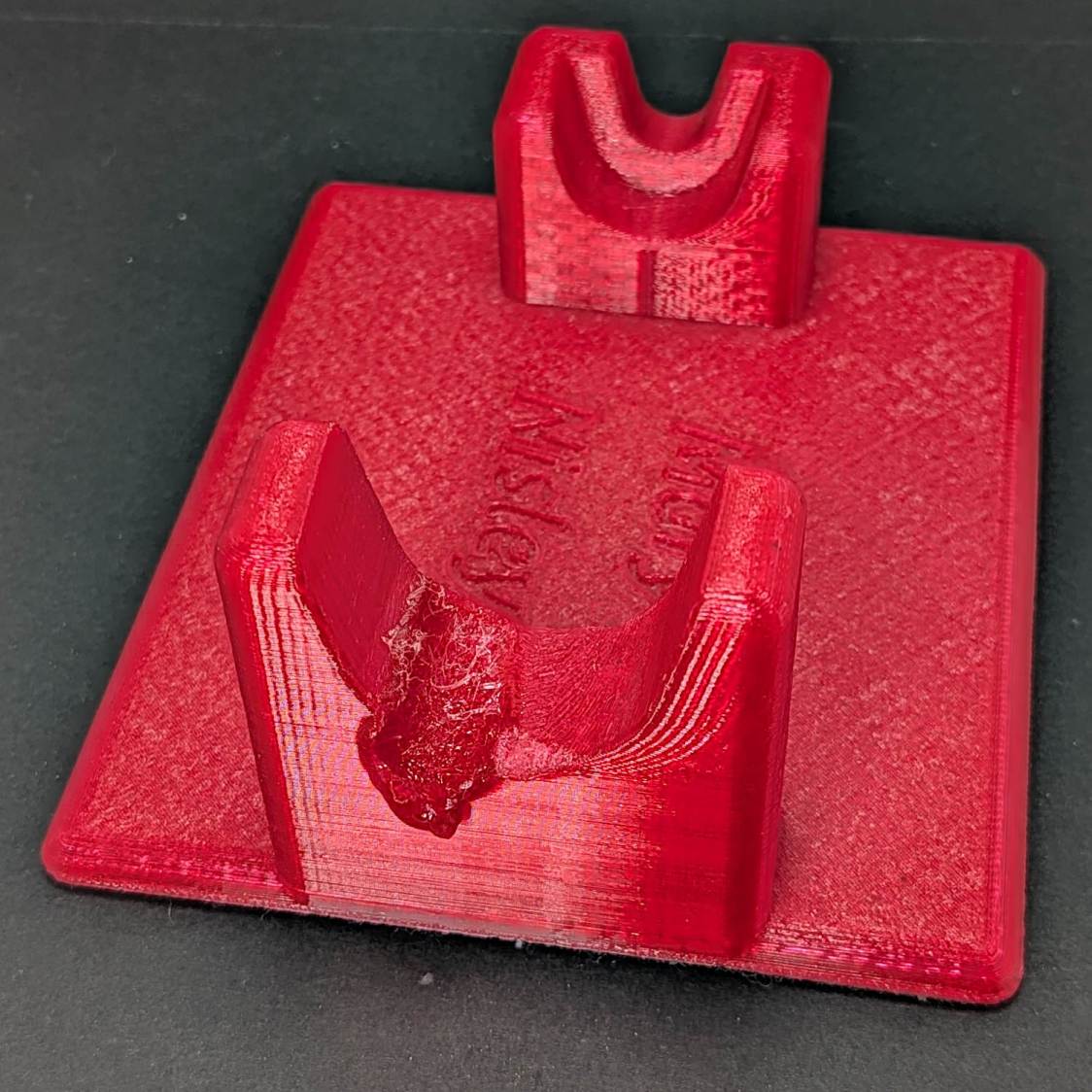
She asked for a new holder that put the iron at a higher angle for easier gripping, which required only slight tinkering to boot the OpenSCAD code into the current decade:
Clover MCI-900 Mini Iron holder – higher angle
The letters stand one layer proud of the surface just to see what that looked like. I think it’s a nice touch.
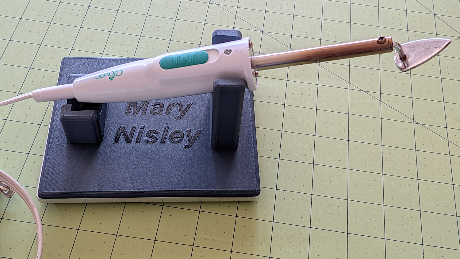
The alert reader will note the cord end isn’t quite snugged into its recess. In normal use, the cord hangs over the edge of the sewing table and pulls the iron into place.
I embiggened the base to fit an aluminum plate from the stockpile, because that same cord tends to pull the holder around on the table. The plate puts enough weight on the silicone rubber feet to hold it firmly in place.
A layer of good double-stick tape strips bonds the aluminum plate to the PETG iron holder, after I once again discovered that craft adhesive sheets do not bond to PETG.
Based on the results from last time, I set the temperature to the cooktop’s maximum 460 °F and, bother fiddling with condensing the moisture on a lid, and let it cook.
Weighing the beads (about) once an hour:
Start: 700 g
1 hr: 678 g
2 hr: 666 g
3 hr: 661 g
The 39 g water loss is 5.6% of the wet weight and 5.9% of the dry weight, which is roughly the amount absorbed by both silica gel and alumina after a month or so in the filament boxes.
During those hours the surface temperature rose from 73 F to 190 °F, although the exact number depends on exactly where the IR thermometer was staring. Stirring the beads to get an average temperature might be more convincing, but not by much.
Exactly how dry the beads become after three hours remains unknown, but the temperature increase suggests most of the water has gone elsewhere.
Cooling the beads in a covered bowl and pouring them into a jug produced a total weight of 767 g, which settled at 770 g over the course of two days; the jug seems reasonably vapor-tight.
Alumina beads seem much less prone to damage by overheating than silica gel beads and have similar performance in the boxes, which makes them a strong contender for the next round.
The last three boxes had 50 g of activated alumina and got fresh doses from the same bottle.
The other boxes had 50 g from the original bottle of silica gel beads and now have regenerated (and likely damaged) silica gel beads.
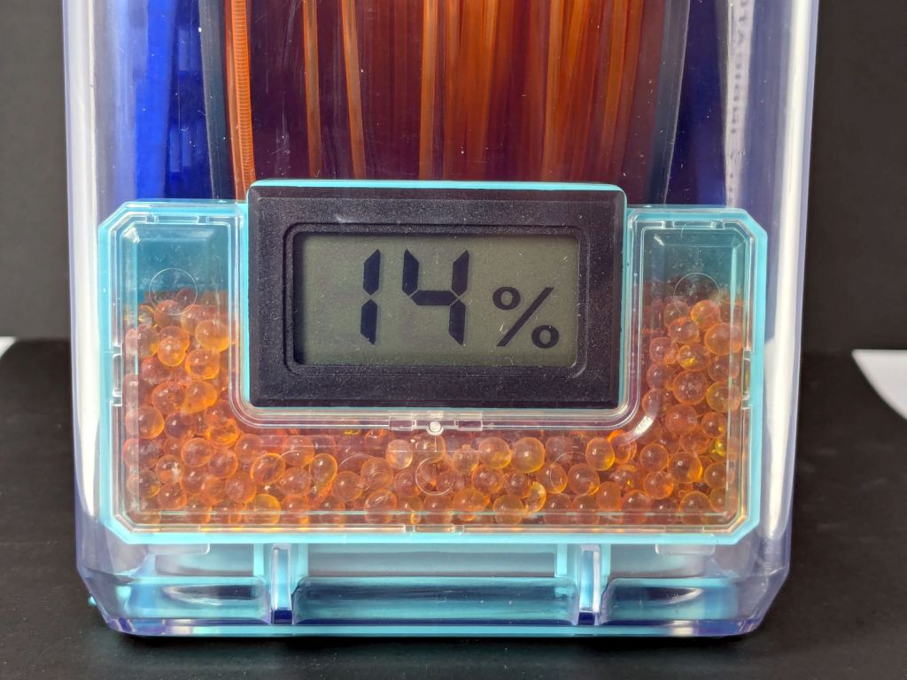
AFAICT, the meter in the orange PETG PolyDryer box isn’t working right, because the humidity indicator card in there has blue spots all the way down to 10%, just like the other boxes. Color differences for meter readings in the teens may be too subtle for my eyes.
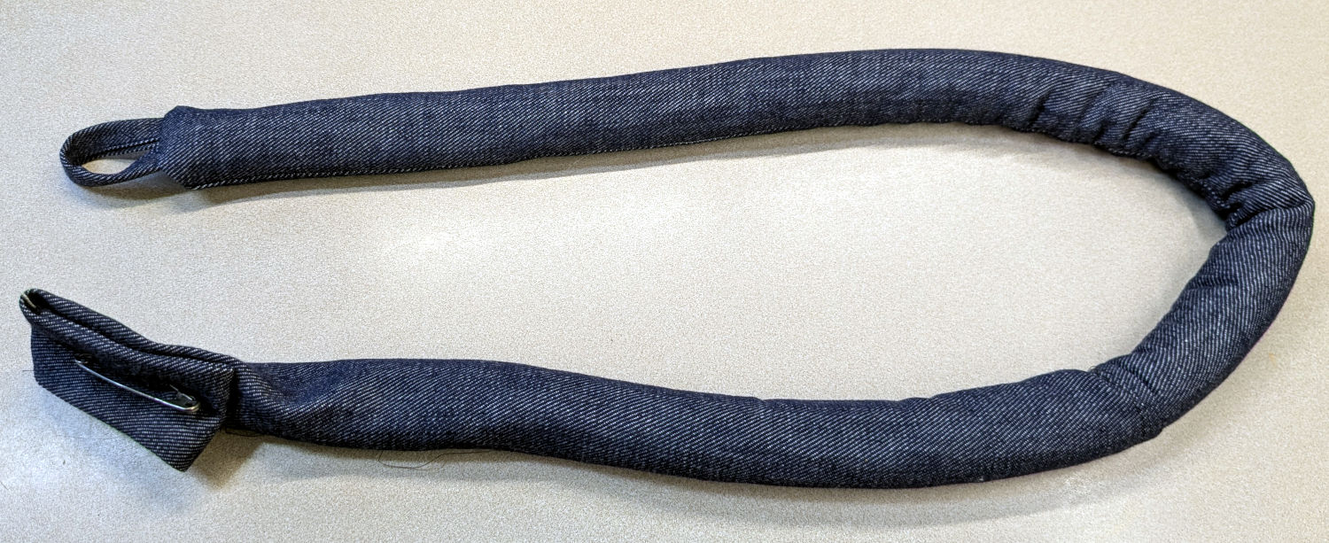
Mary made a frame weight to maintain tension on the fabric in the HQ Sixteen longarm:
Longarm fabric frame weight
It’s a sturdy cloth tube filled with BBs, somewhat like a grossly overweight door snake (a.k.a. draft stopper).
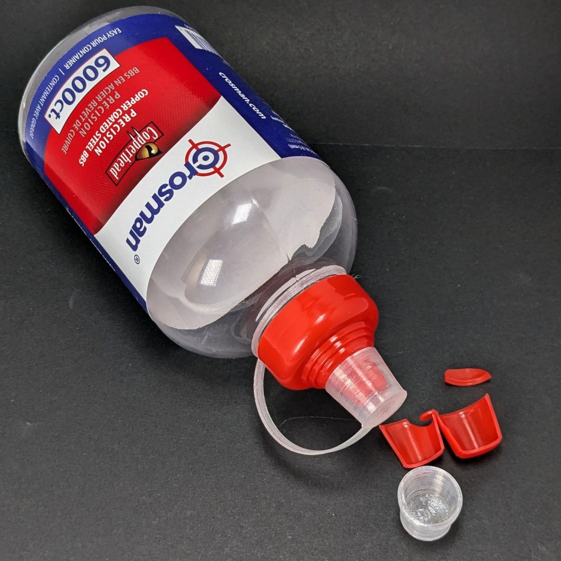
The bottle of 6000 copper-plated steel BBs arrived in an overwrap bag of the sort Amazon applies to all bottled products. This was a Good Thing, because the scrap of packing paper did nothing to cushion the bottle in an otherwise empty box. The bag contained most of the shattered cap and a few BBs, with escapees rattling around inside the box and surely a few left along the way.
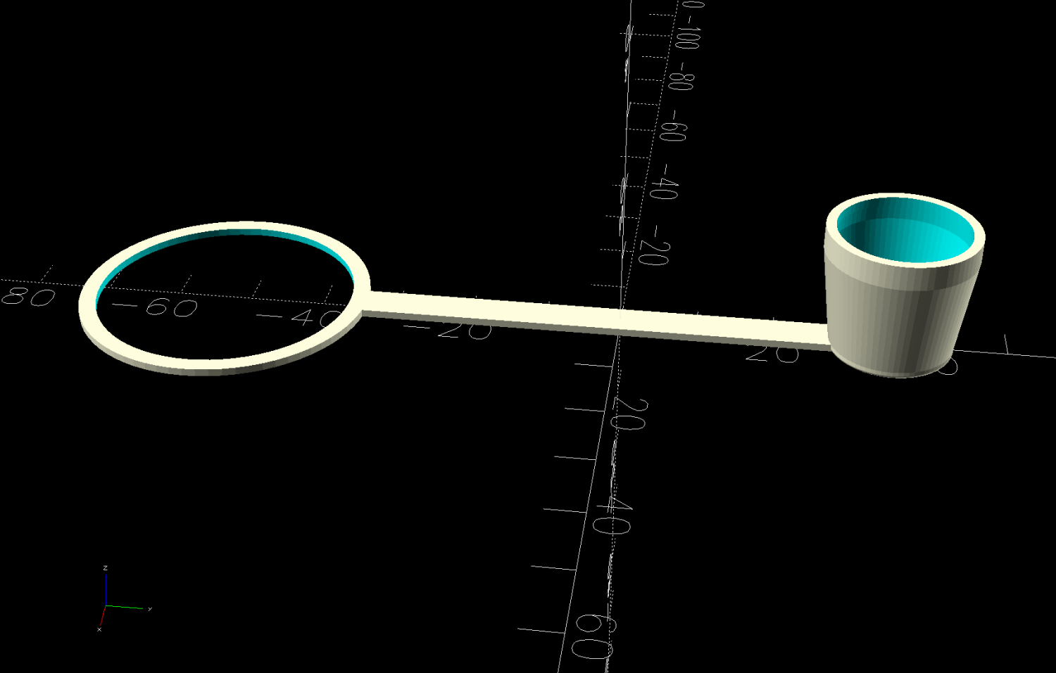
So I conjured a replacement cap from TPU:
Crosman BB bottle cap – solid model – build view
It fits around the bottle neck and snaps onto the spout just like the original:
Crosman BB bottle cap
Except this one is unbreakable.
The strapless TPU cap was a quick test to verify the fiddly shoulder snapping onto the bottle snout:
Crosman BB bottle cap – solid model – section view
As it turned out, we poured all 6000 BBs (minus those few lost-in-transit strays) into the cloth tube, but the bottle will come in handy for something someday.
This file contains hidden or bidirectional Unicode text that may be interpreted or compiled differently than what appears below. To review, open the file in an editor that reveals hidden Unicode characters.
Learn more about bidirectional Unicode characters