Ed Nisley's Blog: Shop notes, electronics, firmware, machinery, 3D printing, laser cuttery, and curiosities. Contents: 100% human thinking, 0% AI slop.
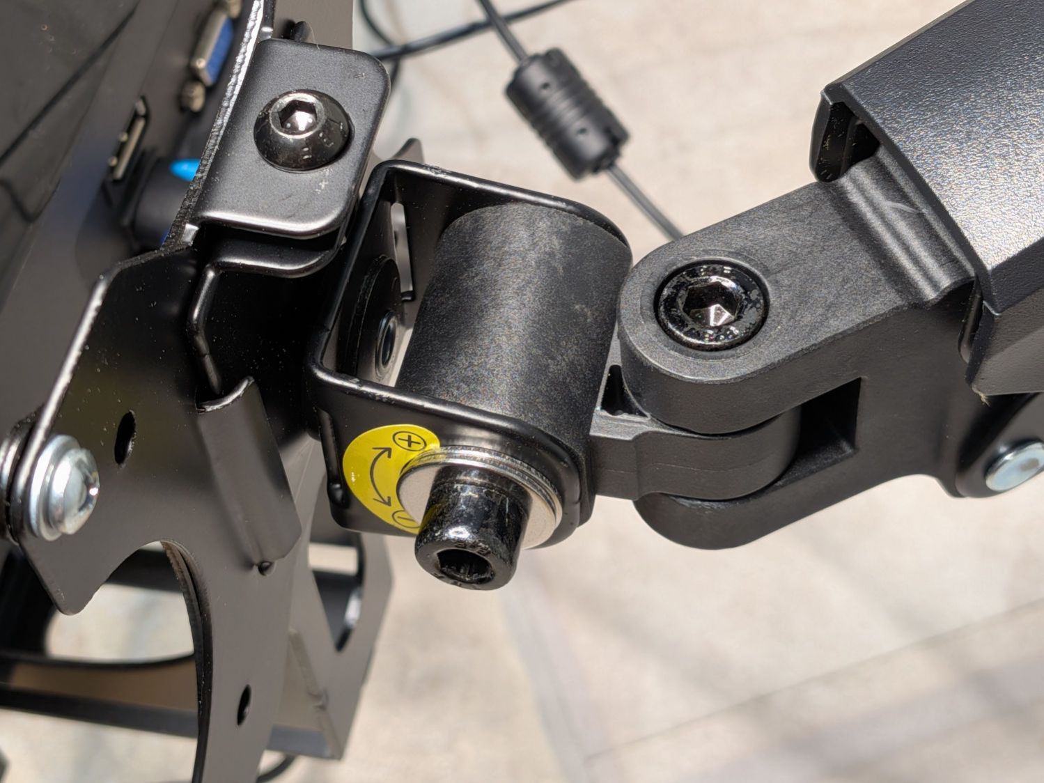
The tilt (it’s really “pitch”, but I can’t make a case for being that pedantic) adjustment on a recently arrived monitor stand / arm was nonfunctional, because the metal clamp had been bent about a millimeter too narrow to fit the plastic core. This is how it should look:
Monitor tilt adjustment – installed
As delivered, the plastic core was 32-ish mm wide and the gap at the base of the metal clamp was 31 mm, so the clamp arms stuck out at an angle on both ends of the core .
Because the cap screw bottomed out on the threads in the far side of the clamp, it couldn’t be tightened enough to force the clamp arms against the core.
Well, if the core is a millimeter too large for the clamp, shortening it should solve the problem; I can always shorten the screw if it comes to that.
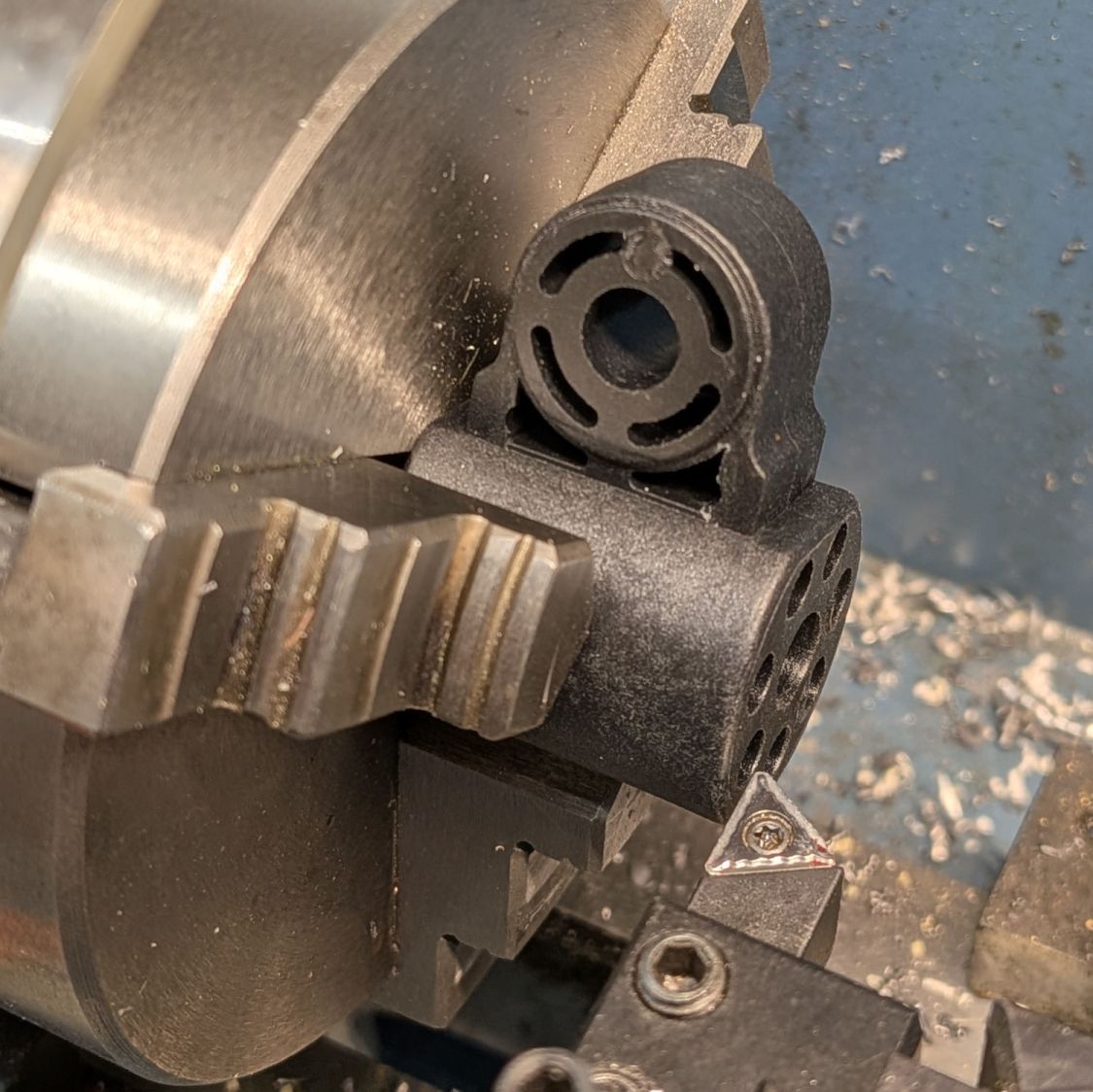
Quick! To the mini-lathe:
Monitor tilt adjustment – lathe setup
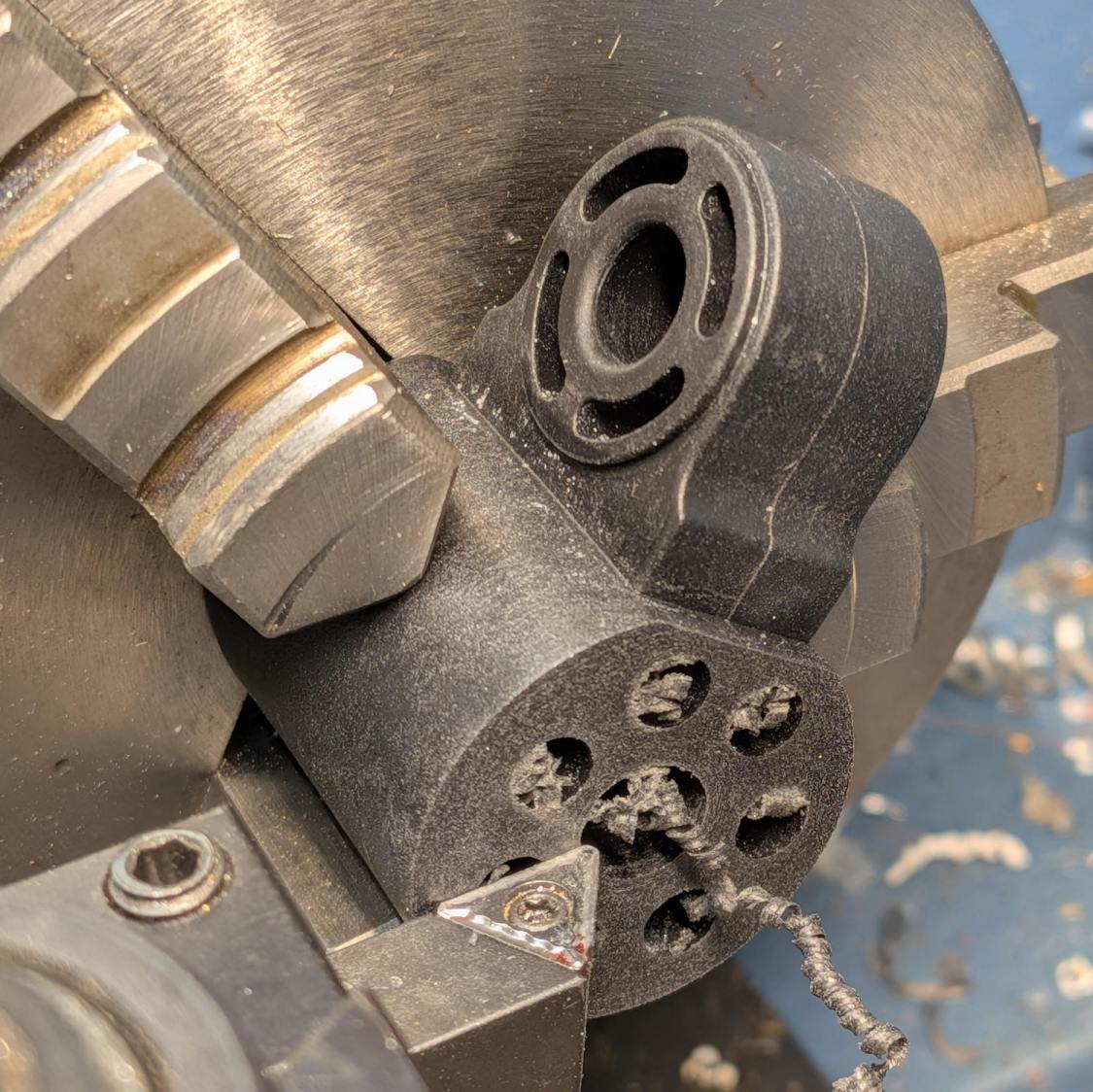
Shaving half a millimeter from each side:
Monitor tilt adjustment – shaved
Twirling a deburring bit in each hole got rid of the swarf.
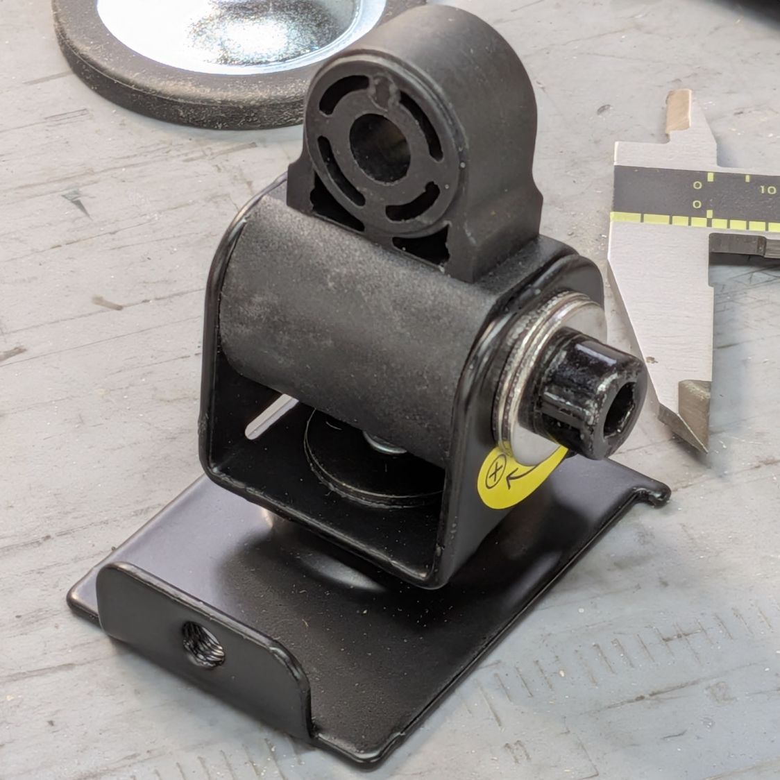
Rather than trimming the cap screw, a pair of fender washers keep it from bottoming out. With the core fitting into the clamp, the arms grip the core firmly on both sides with plenty of friction:
Monitor tilt adjustment – tweaked
I’ve bought this brand of arm before and the most recent pair have definitely been cheapnified from earlier ones. Because only one had a bad tilt clamp, the OEM may be in the middle of a changeover and shipped it with mismatched parts.
I wonder how many stands / arms get returned because they just don’t work?
The OXO pepper mill replacing our worn-out pepper mill arrived filled with peppercorns and, during the ensuing nine months, we established its finest grind setting produced bigger pepper flakes than we prefer. I figured there had to be a way to get the ceramic stones just a little bit closer, even though it has no user-serviceable components inside.
So, we begin.
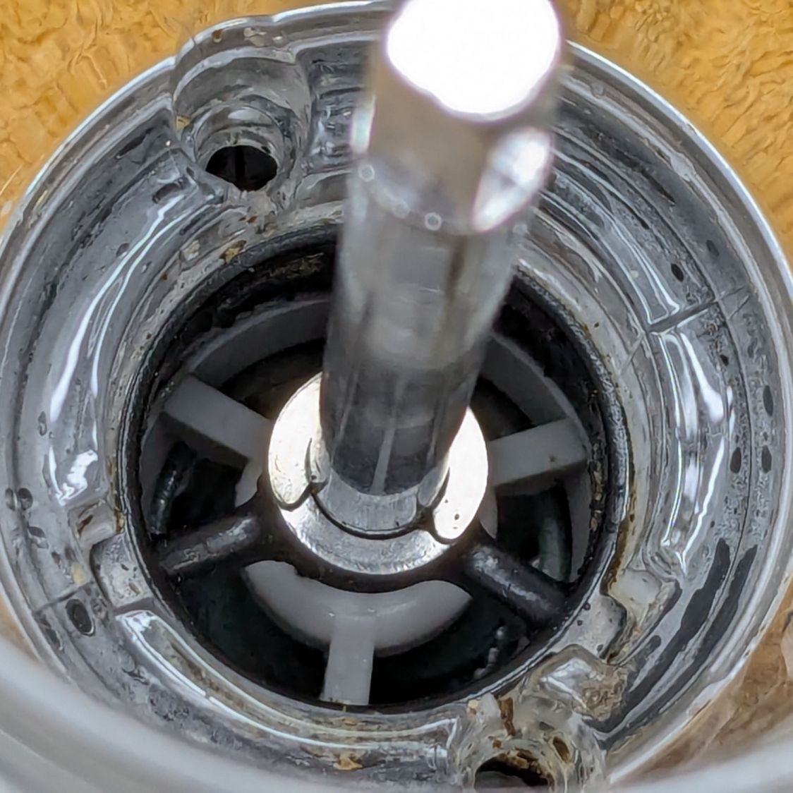
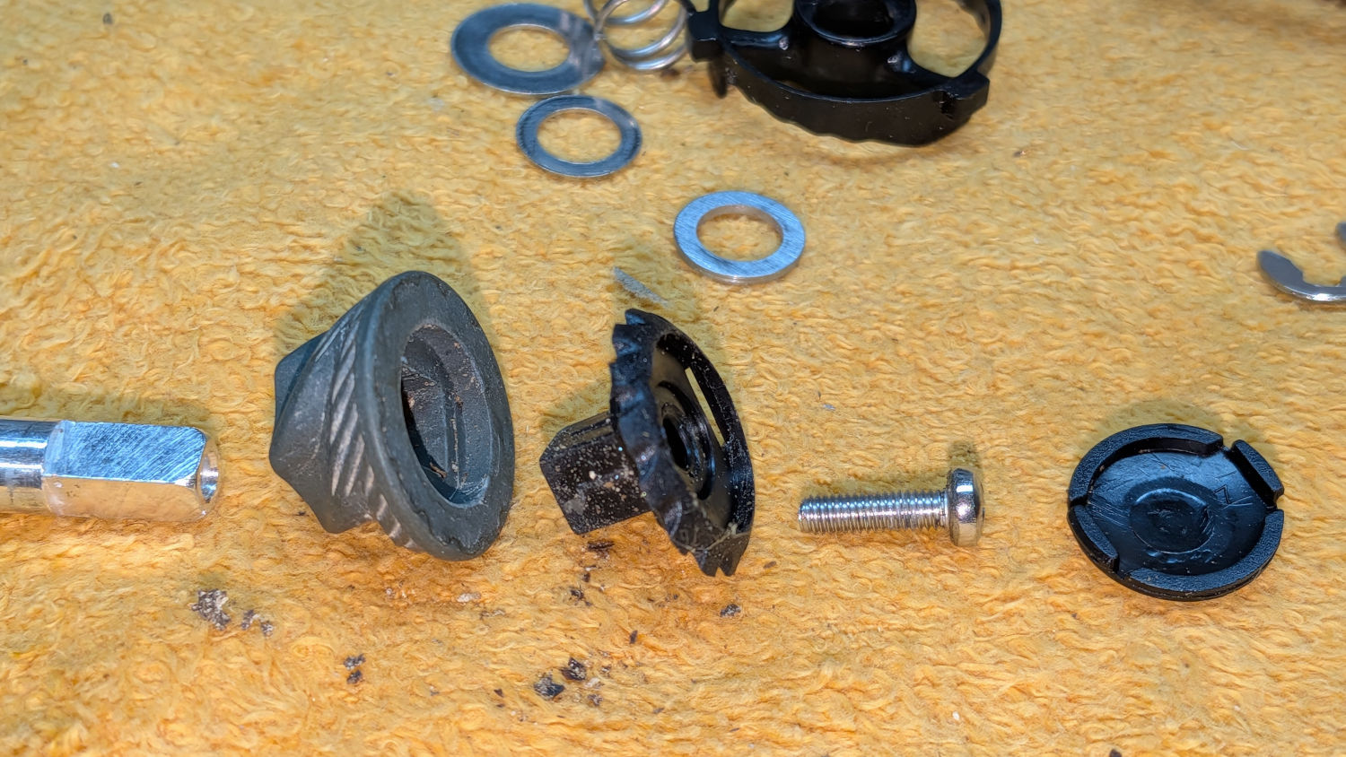
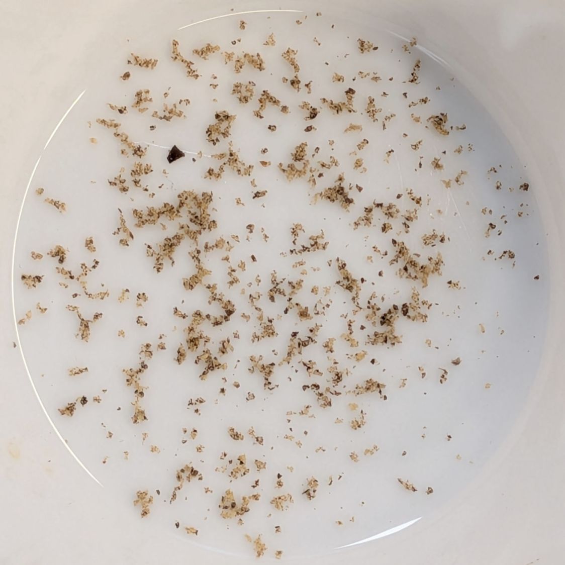
After rinsing out most of the pepper flakes (the remainder appearing in the pictures below) and determining the two obvious screws didn’t release the housing, the Jesus clip on the shaft extending through the peppercorn compartment came under consideration:
OXO Pepper Mill – E-clip on shaft
The washer beyond the clip bears on the black plastic spider. It turns out the thickness of that washer determines the distance between the grind stones at the minimum setting: making it thicker reduces the stone gap and produces a finer grind.
Knowing full well it would be impossible to get the clip back on the shaft in that position, I pried it off.
Spoiler: Don’t do that!
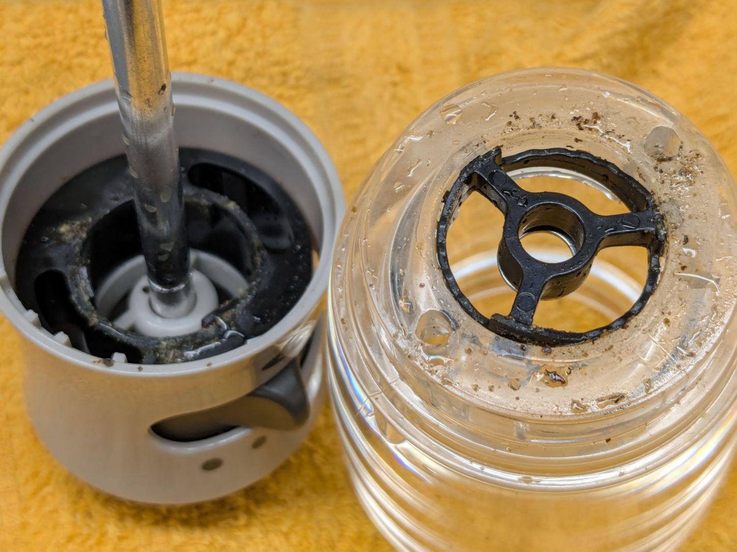
The grind adjustment lever turns the chunky black ring inside the gray housing:
OXO Pepper Mill – grind adjustment rings
Three protrusions on that ring step along notched ramps around the perimeter of the black spider in the clear housing on the right.
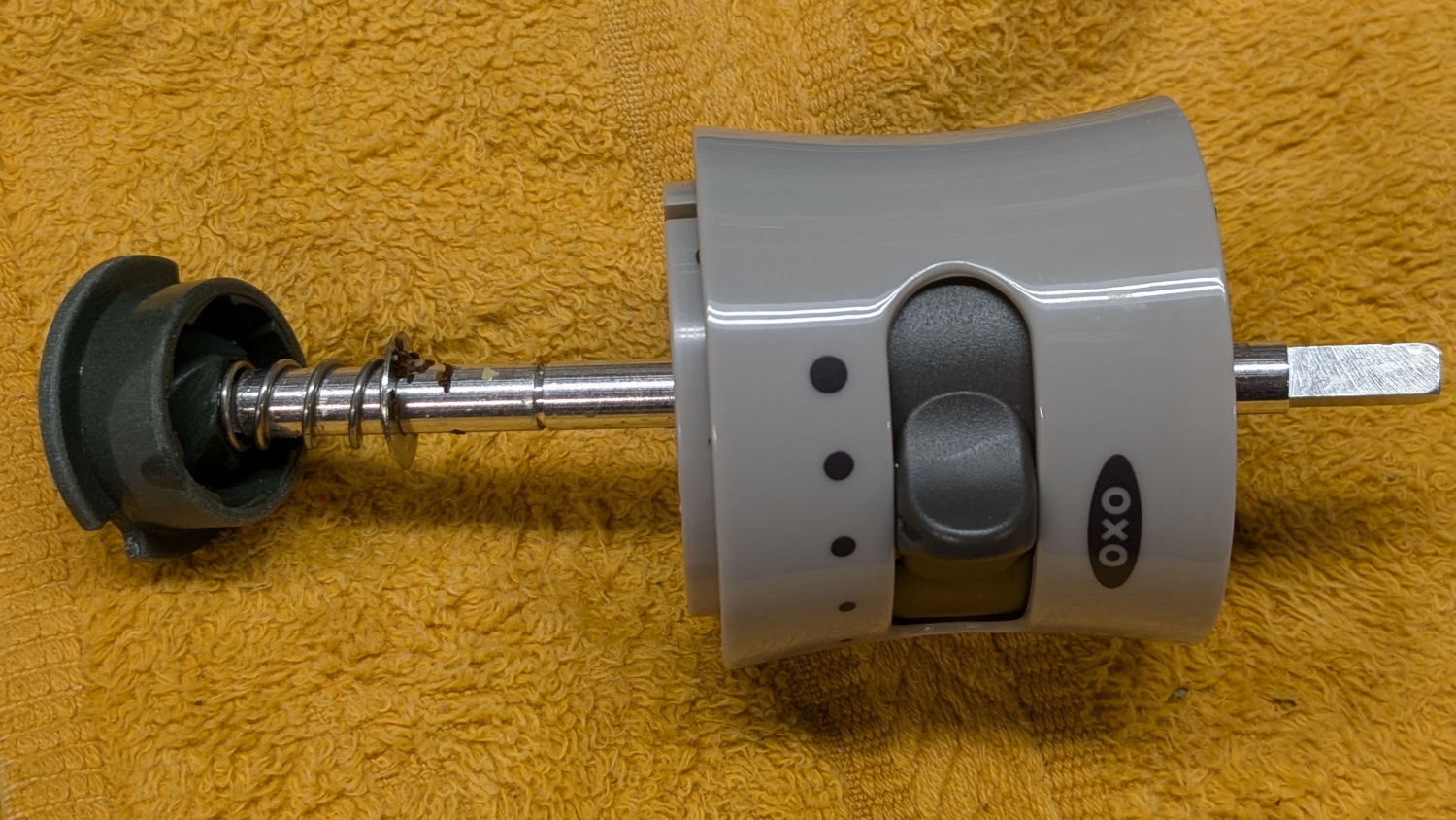
The shaft slides out to reveal the spring under the inner stone, with a second washer bearing against the bore of the gray plastic housing:
OXO Pepper Mill – upper shaft parts layout
As a result, the spring tries to push the shaft and inner stone out of the housing (toward the left). The protrusions on the grind adjustment control how far the shaft can move, with the washer + clip locking the shaft to the spider.
Gentle persuasion extracts the chunky black ring:
OXO Pepper Mill – grind adjust slider
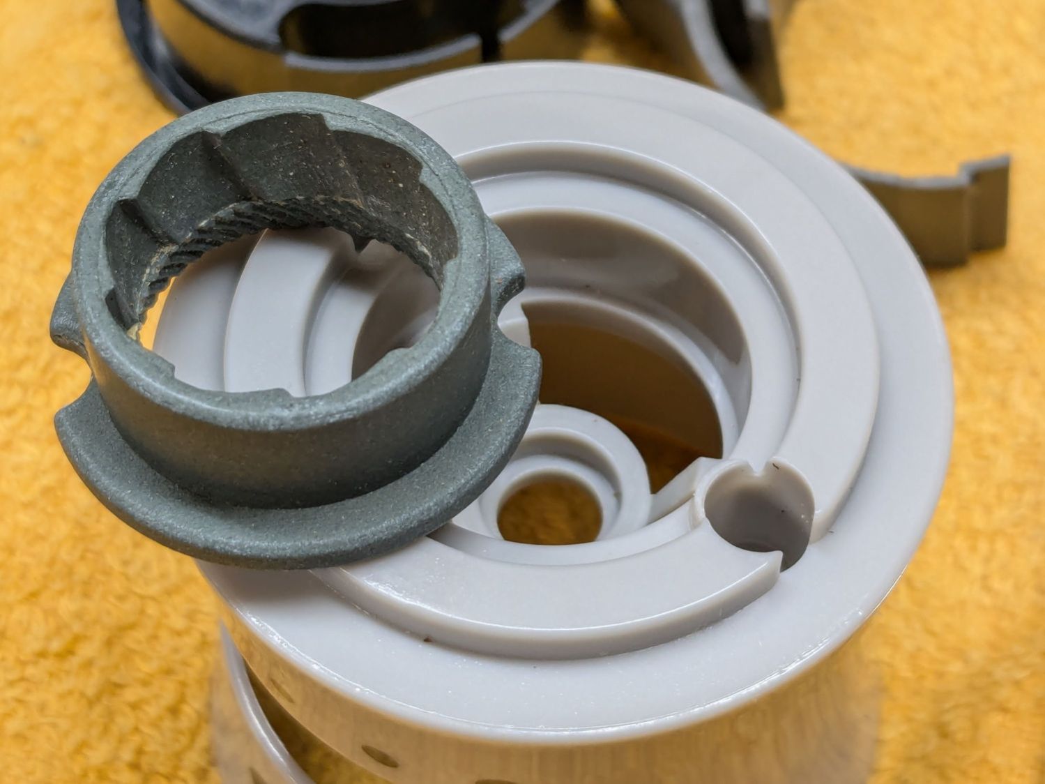
The outer stone fits into a recess in the gray housing:
OXO Pepper Mill – outer stone
One might 3D print a washer fitting under that stone to close the gap between it and the inner stone, but the two screw holes interrupt the ledge enough to suggest the washer would be in two parts divided. If I didn’t have a mini-lathe, that’d be the best way to go.
But I have a mini-lathe, so I made a steel washer slightly thicker than the OEM washer under the clip:
OXO Pepper Mill – turning new washer
The OEM washer:
ID 6.7 mm
OD 10.2 mm
Thick 0.6 mm
Not knowing the right answer, I made a 1 mm washer, which is visibly thicker:
OXO Pepper Mill – 1mm vs OEM washer
Which let me reassemble the pepper mill in reverse order, only to establish reinstalling the Jesus clip deep down inside the housing is, in fact, impossible.
Taking everything apart again let me contemplate the inner stone on the shaft, leading to the discovery it could slide very slightly on the shaft. More pondering revealed a slight seam in what I had taken as a monolithic black cap:
OXO Pepper Mill – inner stone assembled
Applying gentle suasion between the stone and the cap with a plastic razor blade enlarged the seam into a gap. Much to my surprise, further prying popped the top off the cap:
OXO Pepper Mill – inner stone cap
Happy dance in full effect!
Removing the screw let everything slide off the top of the shaft:
OXO Pepper Mill – inner stone parts
Freeing that end of the shaft meant I could install the clip on the bench, add various parts while sliding the shaft through the housing, then tighten the screw to snug everything down.
As with most activities, it’s trivially easy when you know the trick.
Whereupon I discovered the new 1 mm washer jammed the two stones firmly together at the finest grind setting, so the correct washer will be somewhere between 0.6 and 1.0 mm thick:
Back to the lathe for a 0.8 mm thick washer
Dismantle pepper mill
Swap washers
Reassemble
Verify smooth turning at finest setting
Fill with peppercorns
Give it a twist
A shower of pepper flakes in a cup:
OXO Pepper Mill – finer grind
The mill undergoes a full qualification test tomorrow morning, but those flakes look much better.
Fun fact: the OXO pepper mill holds 2.0 oz of peppercorns, so we use 0.033 oz = 940 mg of pepper every day.
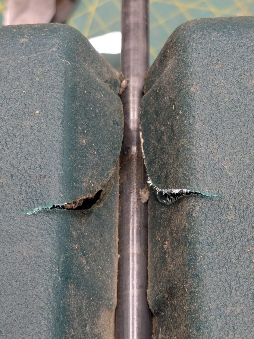
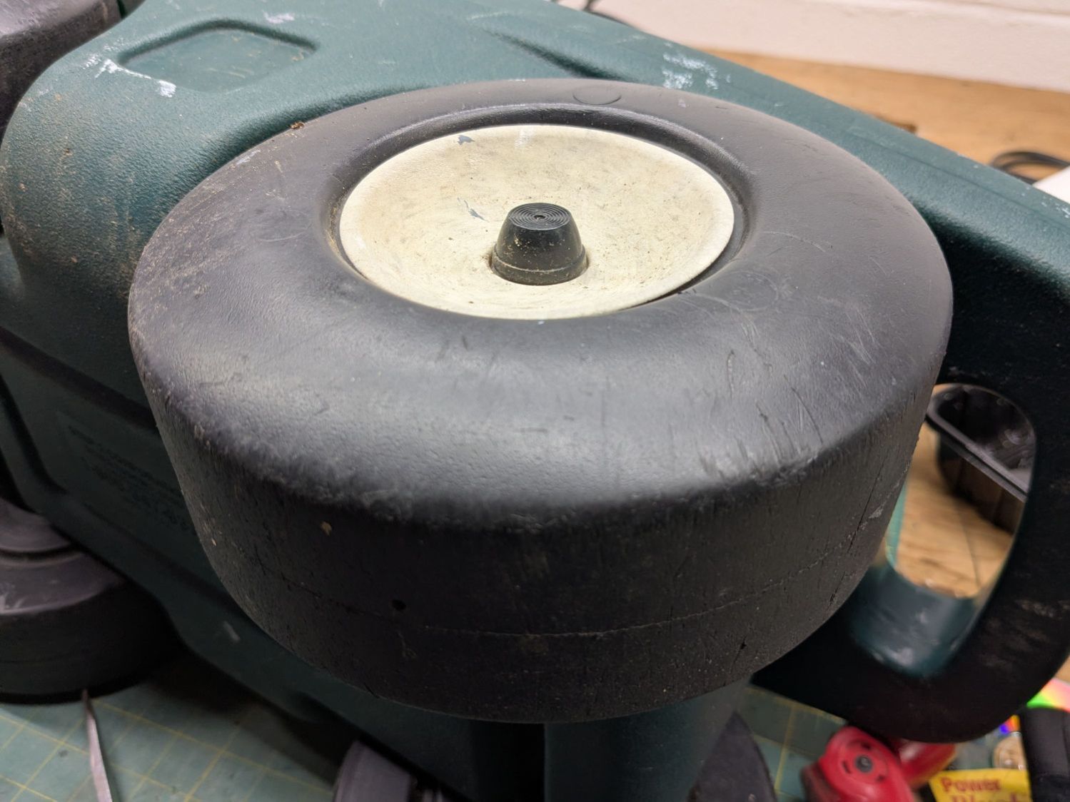
The cart in Mary’s Vassar Farm plot returned in need of repair:
Garden Seat – fractured body
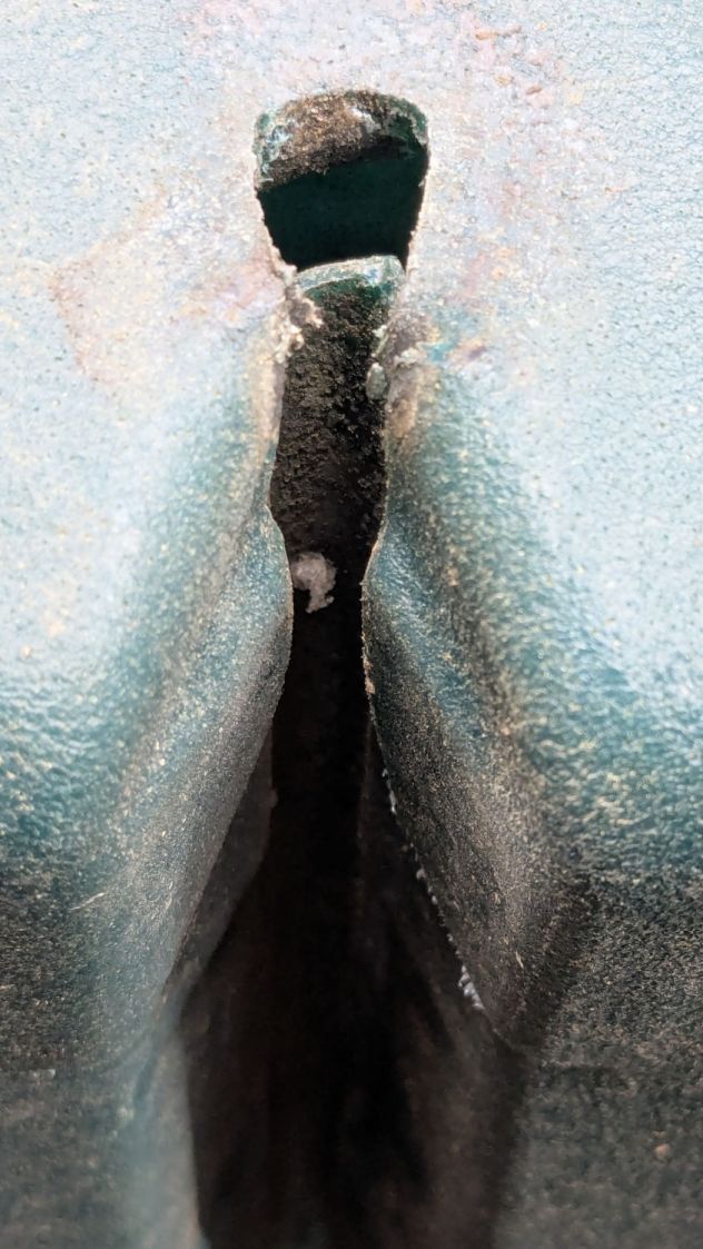
Those fractures near the end of the axle let the axle erode the side wall:
Garden Seat – eroded body
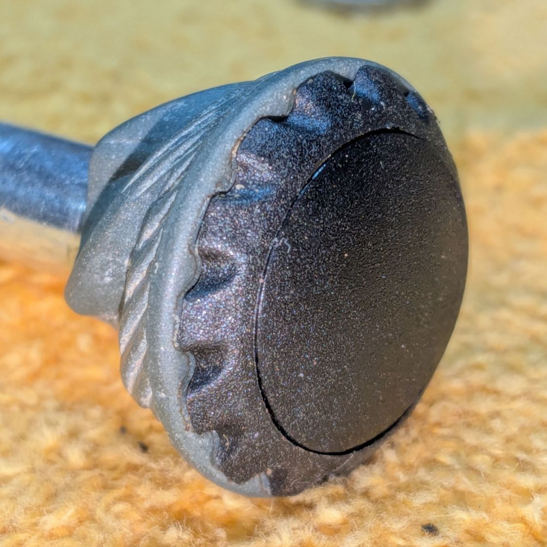
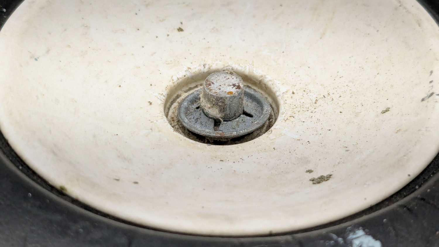
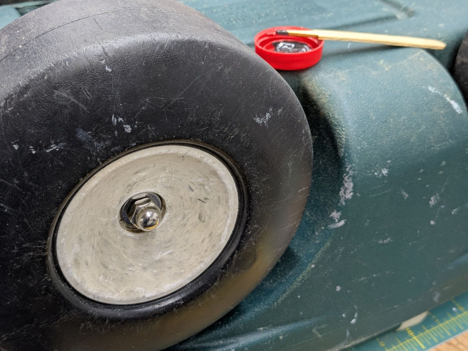
This will obviously require some sort of reinforcement on the body holding the axle, but the first challenge involved getting the wheels off the axle:
Garden Seat – axle cover
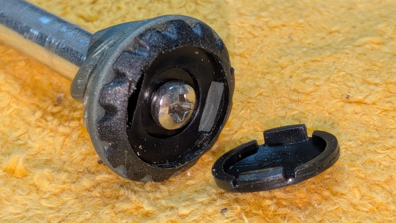
Some brute force revealed the hub covers snapped over an install-only locking fastener:
Garden Seat – axle retaining clip
More brute force cut those fasteners (a.k.a. star-lock washers) to get the wheels off the axles.
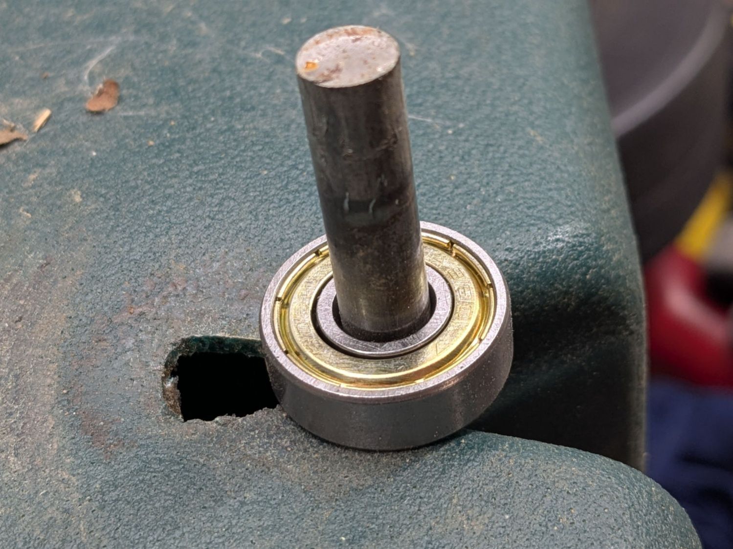
While contemplating the situation, a box of 606 bearings (as used in the PolyDryer auto-rewind spindles) failed to scamper out of the way and produced a victim fitting perfectly on the 8 mm axle:
Garden Seat – bearing idea
I regard such happenstance as a message from the Universe showing I’m on the right track. The alert reader will note the axle should not rotate, but does sport scars showing it’s done some turning in the recent past, so the bearing may not be a completely Bad Idea™.
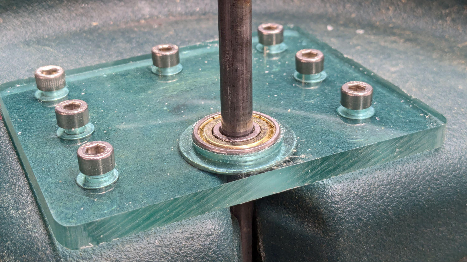
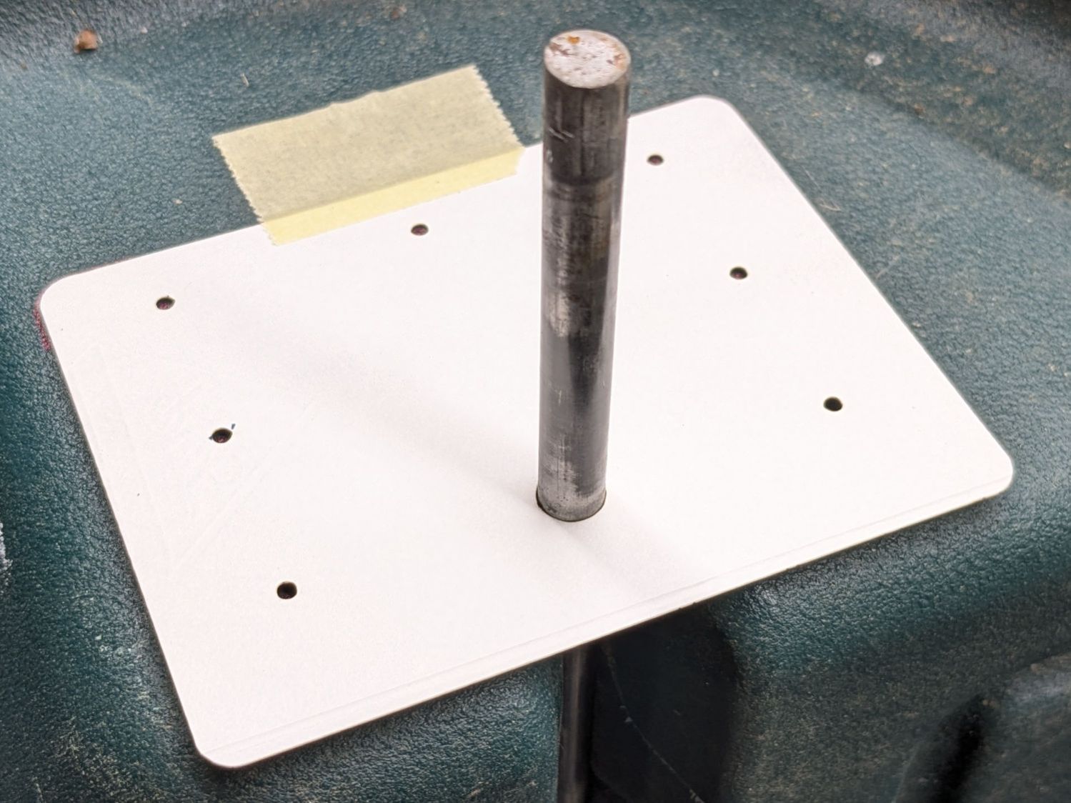
Finding a Lexan snippet exactly as thick as the bearing suggested bolting a plate across the side of the body to support the bearing, like this:
Garden Seat – reinforcing plate installed
Some layout work in LightBurn produced a template to mark the body for hand-drilling the holes:
Garden Seat – drill marking template
In retrospect, that was a mistake. I should have:
Laser-cut an MDF sheet to make a drill jig
Drilled one hole and inserted a screw
Drilled the rest of the holes in exactly the right places
Instead, three of the holes in that nice Lexan sheet ended up slightly egg-shaped to adjust for mis-drilled holes in the body.
I squeezed 5 mm rivnuts into whatever fiber-reinforced plastic they used for the body, which worked better than I expected. They’re intended for sheet metal, so I set the tool for 5 mm compression and they seem secure. I hope using plenty of screws across a large plate will diffuse the stress on each screw.
In this situation, I regard JB KwikWeld epoxy as “removable with some effort”, as opposed to the destruction required with those star-lock washers. High-strength Locktite might also be suitable, but I do not anticipate ever having to remove these again for any reason and do not want the nuts to fall off in the garden.
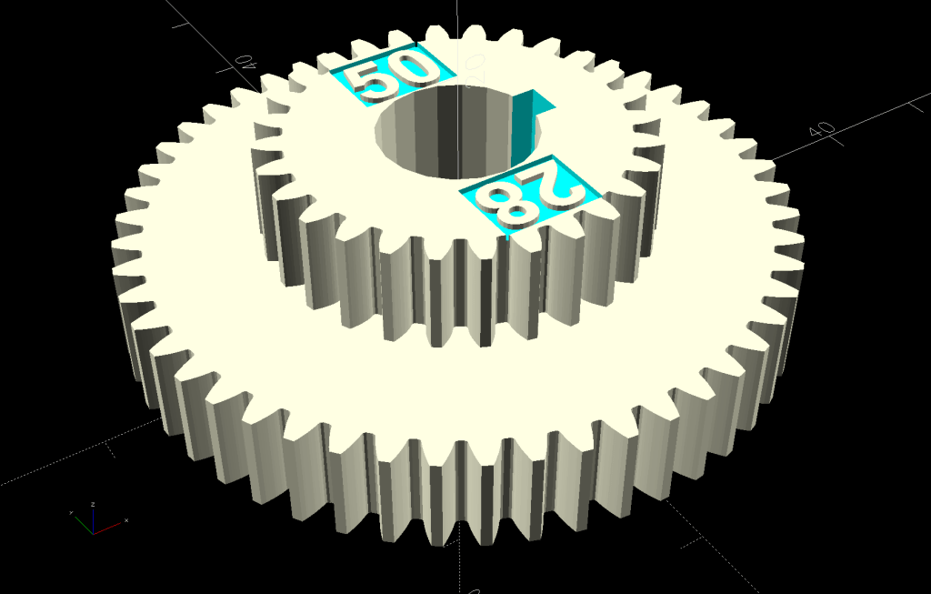
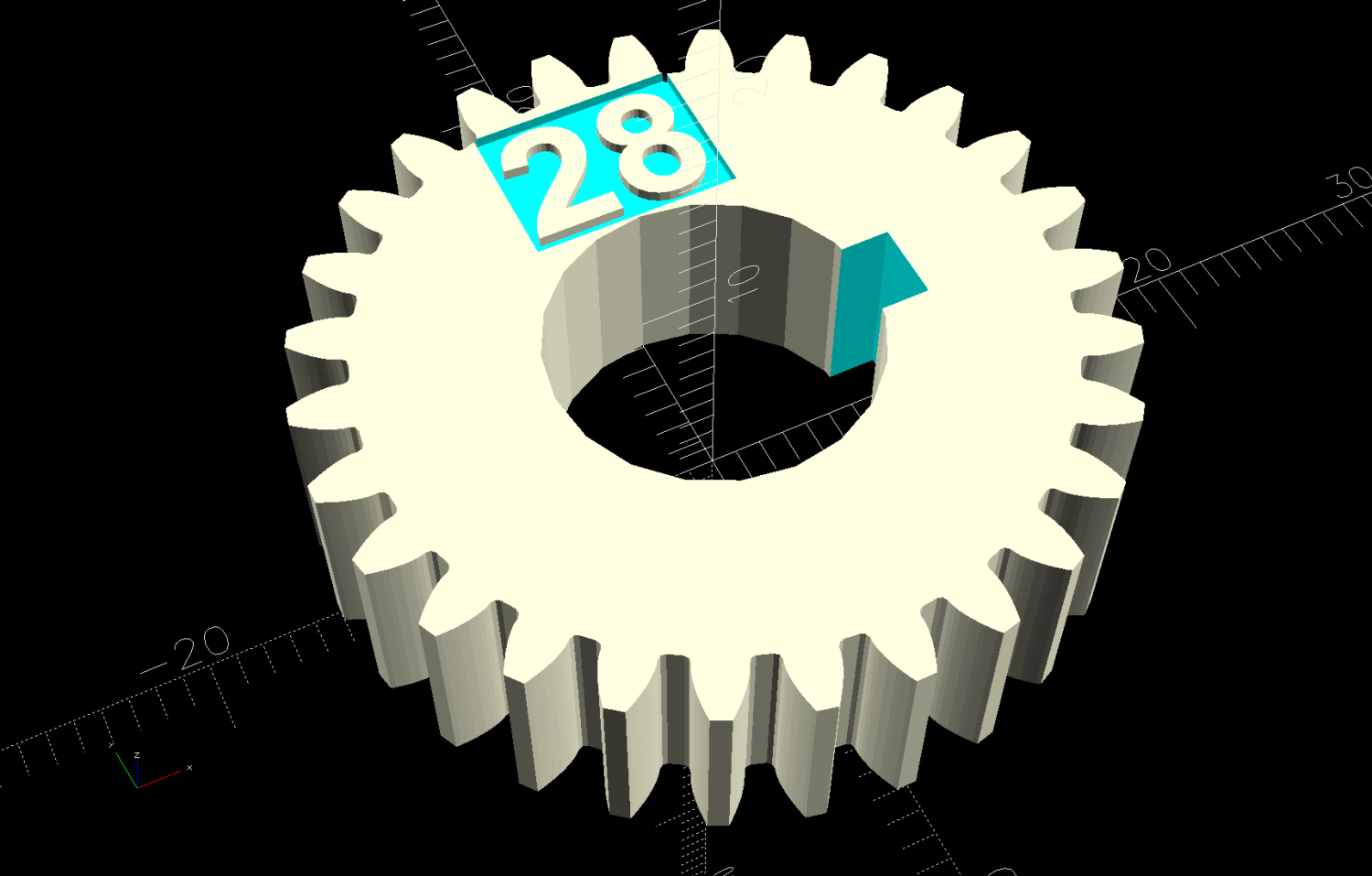
The labels now snuggle closer to the shaft and (barely) fit on smaller gears:
Mini-lathe stacked change gears – 28T – solid model
The stacked B-C gears for the jack shaft work as before, with both labels on the top gear:
Mini-lathe stacked change gears – 28-50T – solid model
The admittedly flimsy motivation for all this was to make a 28 tooth gear to cut a 0.9 mm pitch, thus filling an obvious hole in the gear table.
My collection of gears could do 21-60-81-50, but the 81 T gear collides with the screw holding the 21 T gear. Rearranging it to 21-50-81-60 showed the B-C gears exceeded the space available.
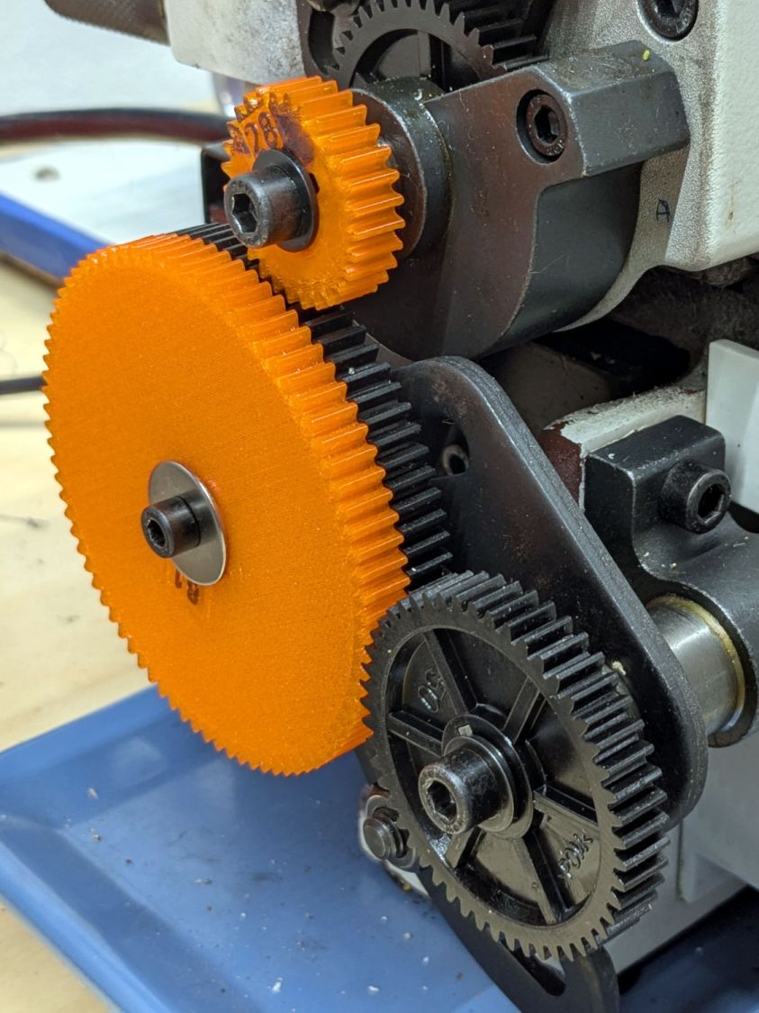
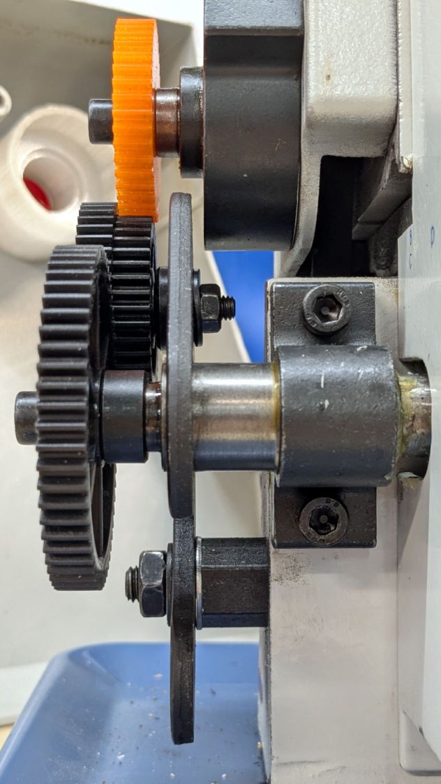
Because it’s all ratios and a 28 T gear is 4/3 bigger than 21 T, reducing the rest of the train by 3/4 should work. In fact, it produced a reasonable 28-80-81-50 chain:
Mini-lathe change gears – 28T installed
The fact that I do not anticipate ever needing to cut a 0.9 mm pitch has nothing whatsoever to do with it; that gear will surely come in handy for something.
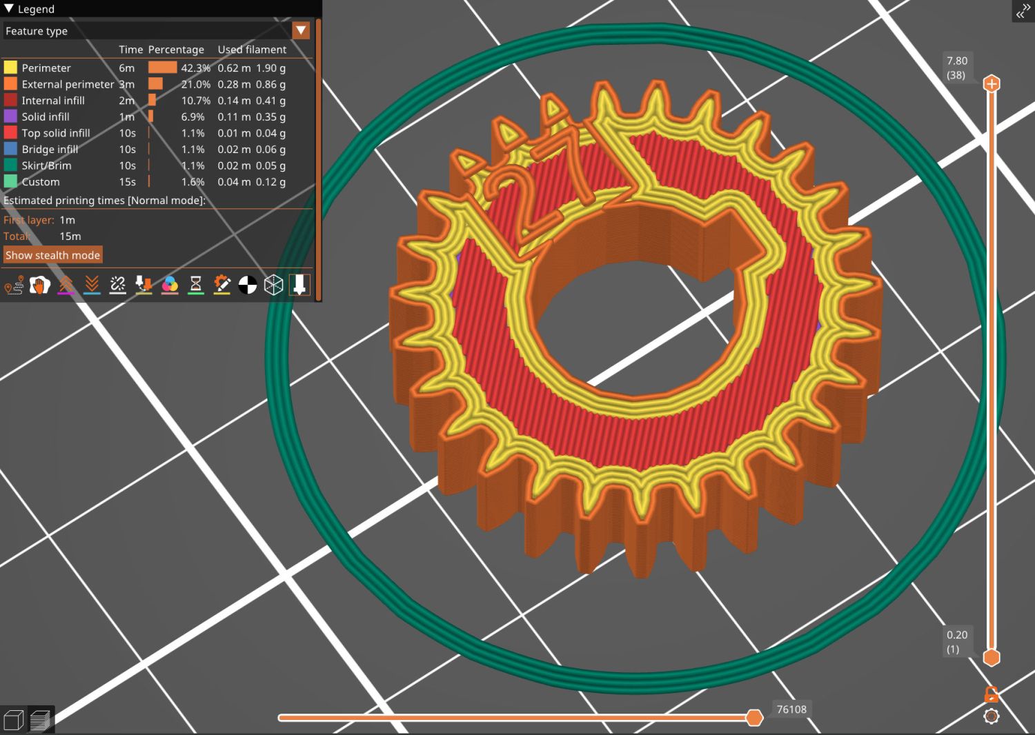
While I was at it, I made a 27 T gear, because 27 = 21 × 9/7:
This file contains hidden or bidirectional Unicode text that may be interpreted or compiled differently than what appears below. To review, open the file in an editor that reveals hidden Unicode characters.
Learn more about bidirectional Unicode characters
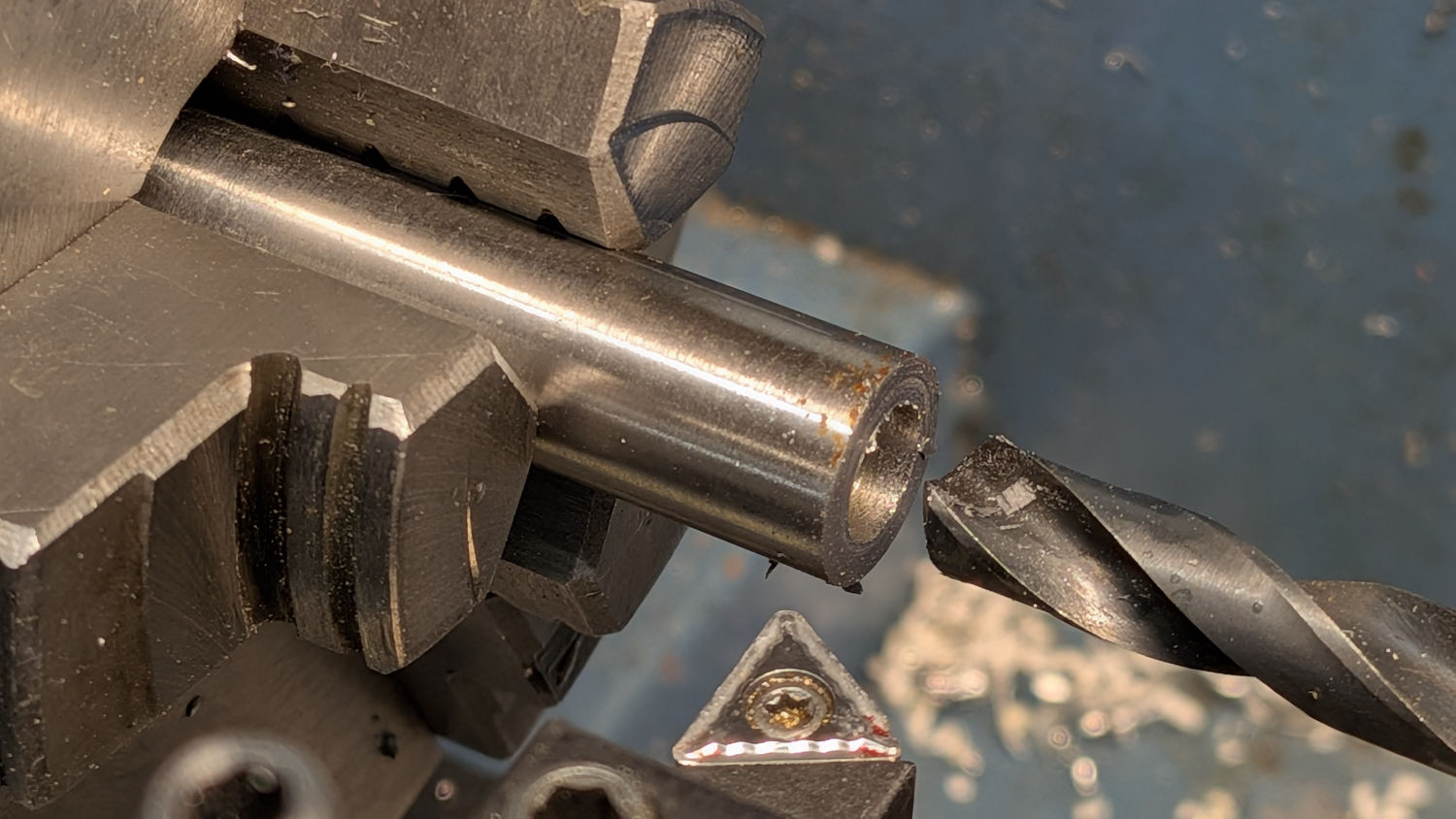
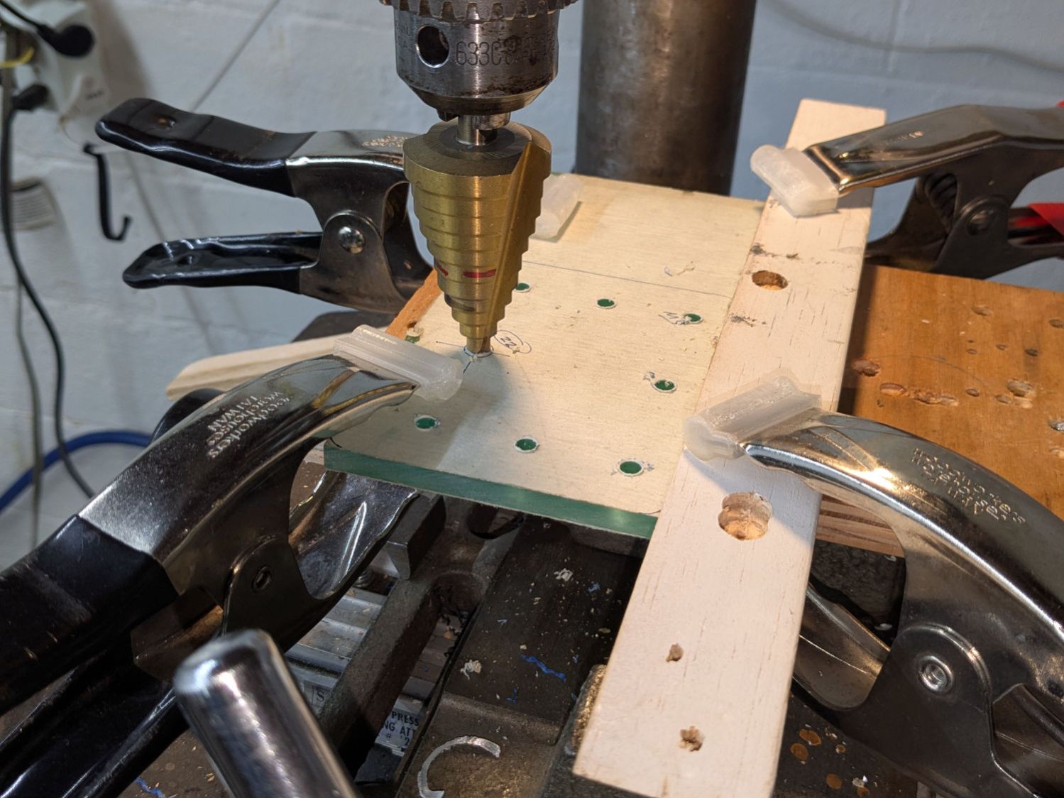
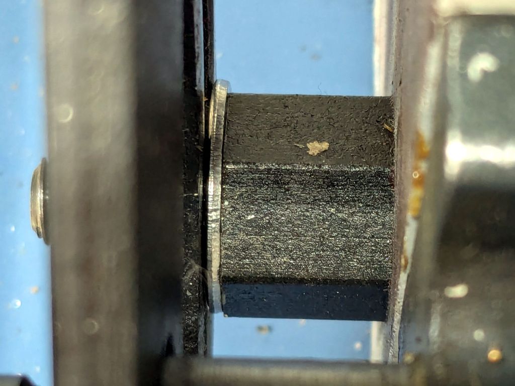
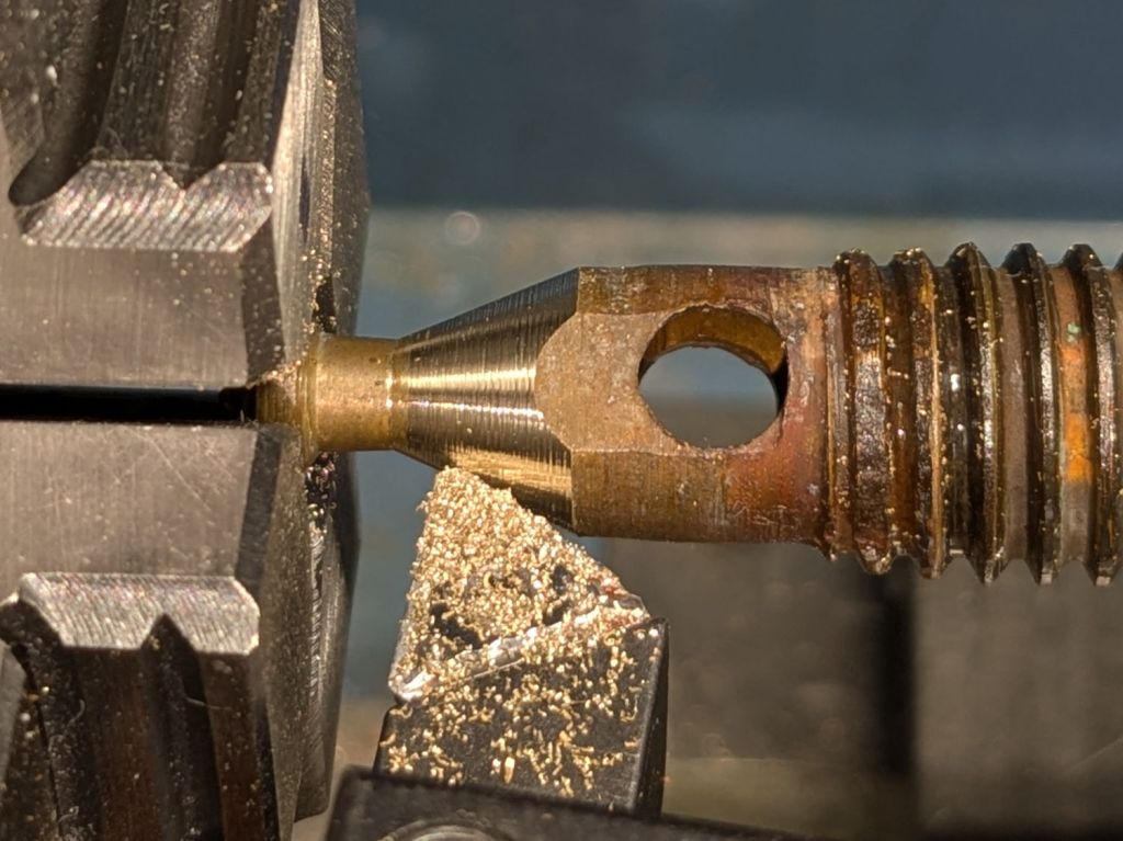
I intended to single-point a few turns on an 8 mm axle to ease running an M8-1.25 die over it, thus making a thread for a nut securing a wheel (about which, more later). This required selecting the change gears for a 1.25 mm thread pitch, the installation of which proved sufficiently awkward to give me the opportunity to discover a washer spacing the banjo just a little farther outward would improve the gear alignment:
Mini-lathe change gear banjo – shim detail
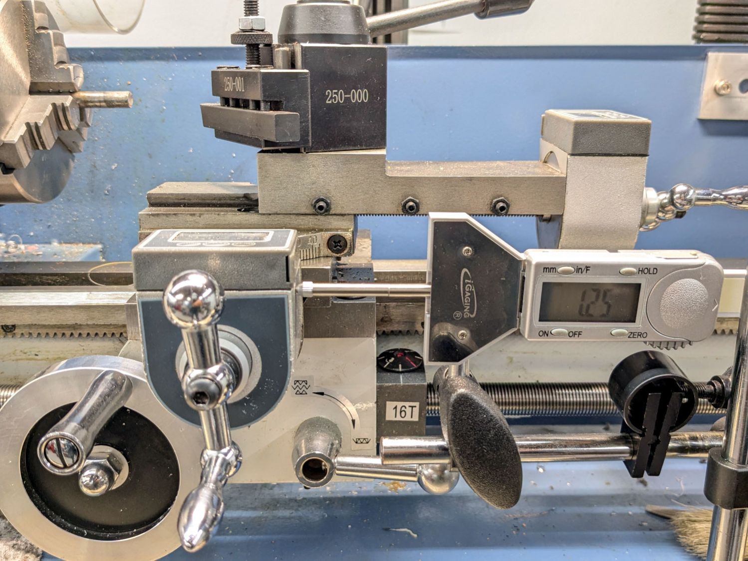
The overview shows how moving the whole banjo just a bit leftward better aligned black Gear B with respect to orange Gear A:
Mini-lathe change gear banjo – shim overview
From A to D, a 1.25 mm pitch uses 42 40 45 60 tooth gears. The 42 tooth gear supplies the magic required to convince a hard-inch 16 TPI leadscrew to produce good-enough metric pitches.
In addition to the usual hassle, the main reason the process took so long is doing having to do it twice. After I swapped Gear C and Gear B on the jockey shaft in the middle, the leadscrew produced the correct 1.25 mm motion for one turn of the chuck:
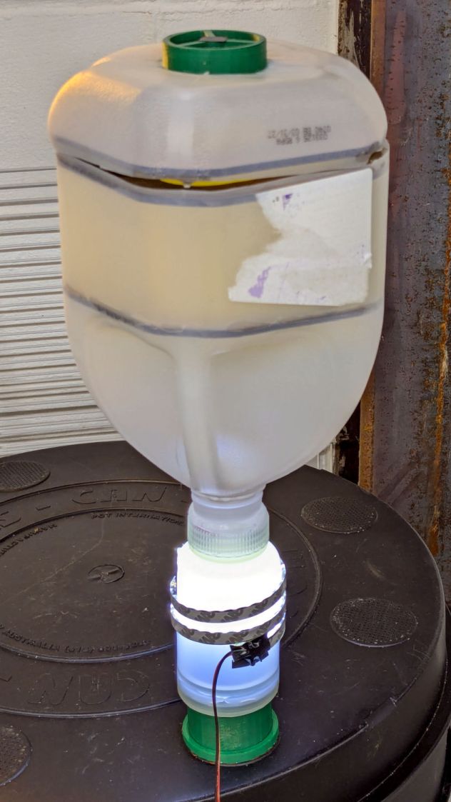
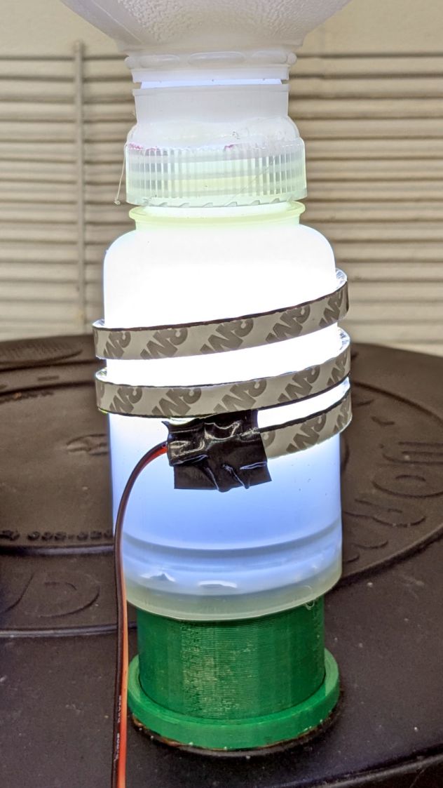
Despite freezing the kitchen scraps going into the worm bin since the previous fruit fly infestation, a zillion flies are now in residence. Lacking the peppermint-stick tube of yesteryear, I conjured another fly trap from common household items:
Worm Bin Fly Trap – overview
The gap around the top got a strip of tape after I took the picture.
I was all set to 3D print a threaded adapter to join the two bottles when I realized they already had lids. A few minutes of lathe work added a passageway:
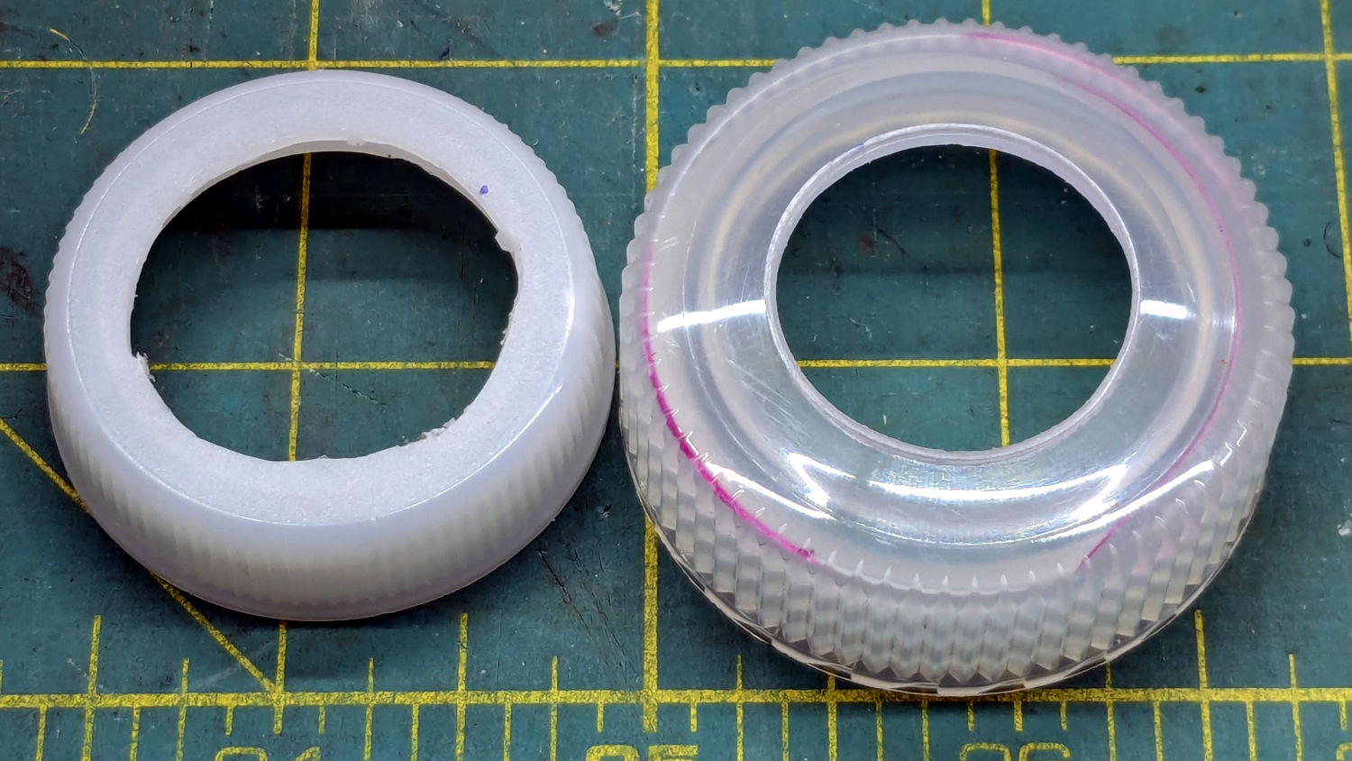
Worm Bin Fly Trap – Bottle caps
They’re held together by a generous ring of hot melt glue:
Worm Bin Fly Trap – lighting detail
The LED strip provides enough light to simultaneously attract the flies and repel the worms.
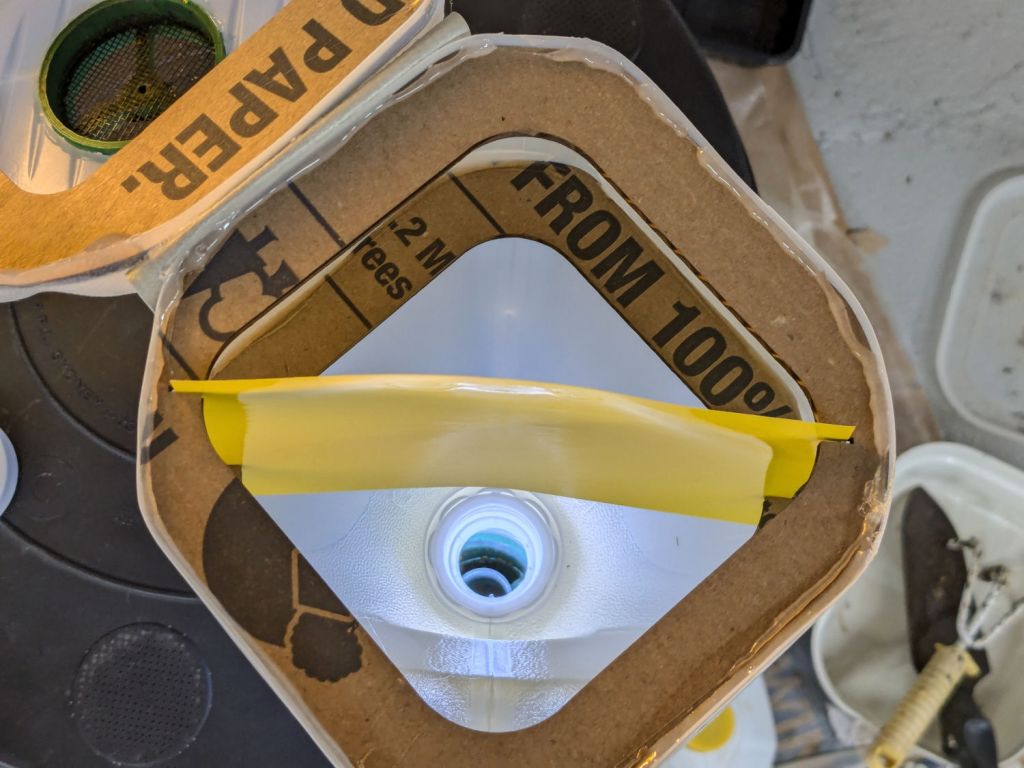
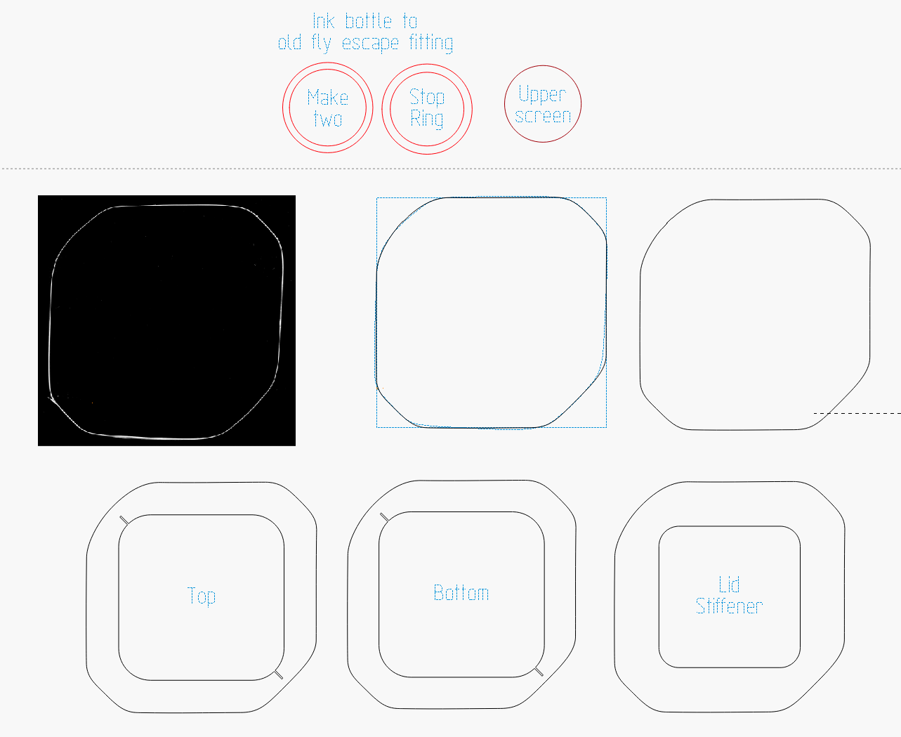
The laser cuttery looks like this:
Worm Bin Fly Trap – LightBurn parts
The white shape in the black block is a scan of the cut-open jug, with the other shapes in that row being rectangularized versions. The two tiny notches in the Top and Bottom shapes hold the sticky paper.
The two rings at the top adapt the LED-wrapped bottle to the existing fitting on the worm bin from the previous episode. They’re visible as shadows near the bottom of the bottle.
The circle is a laser-cut hole in the gallon jug bottom for the screened plug made for the pepermint-stick tube; the less said about that operation the better.
So far, so good, although previous experience suggests the flies will be breeding ahead of their (considerable) losses for the next few weeks.
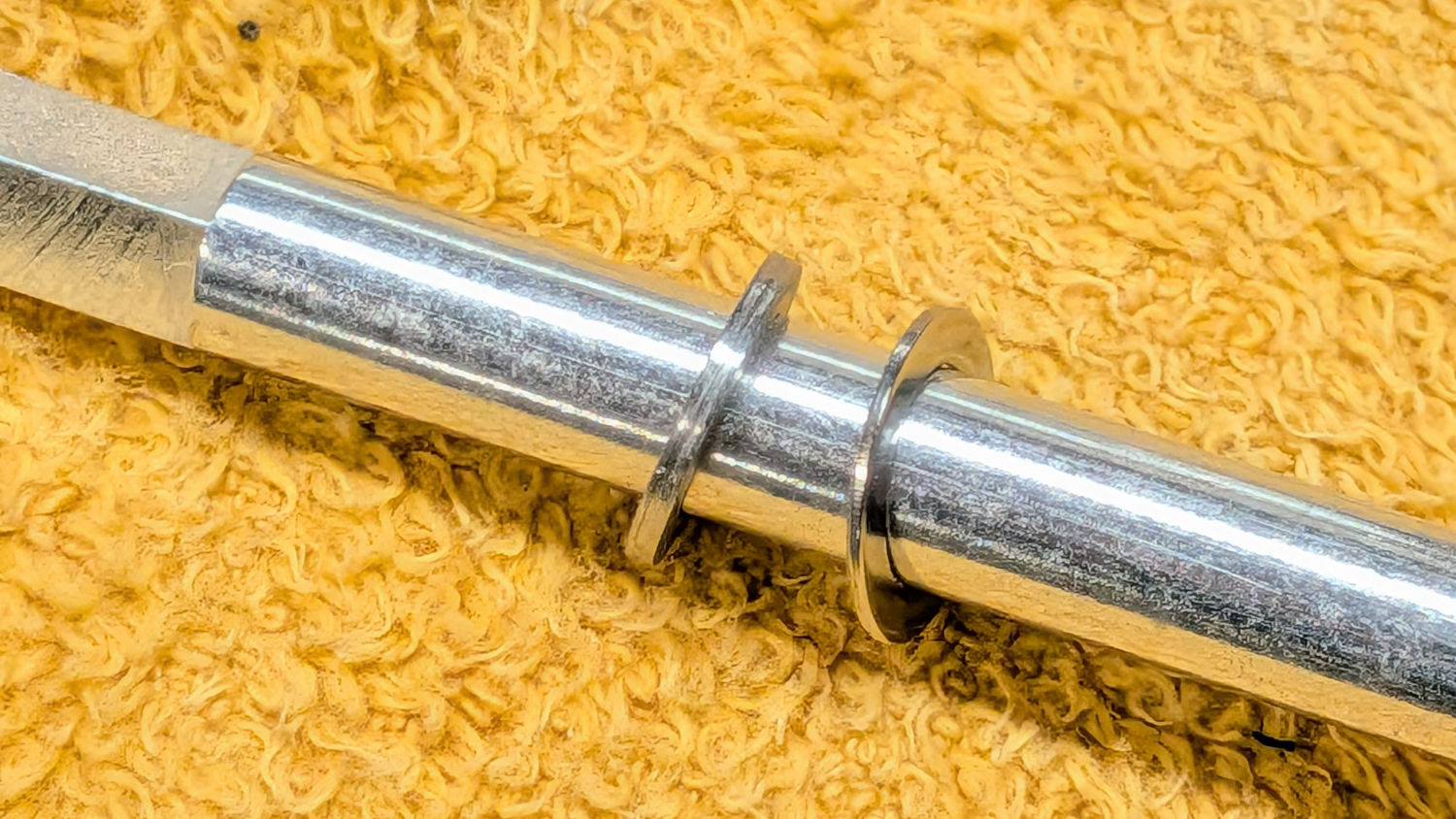
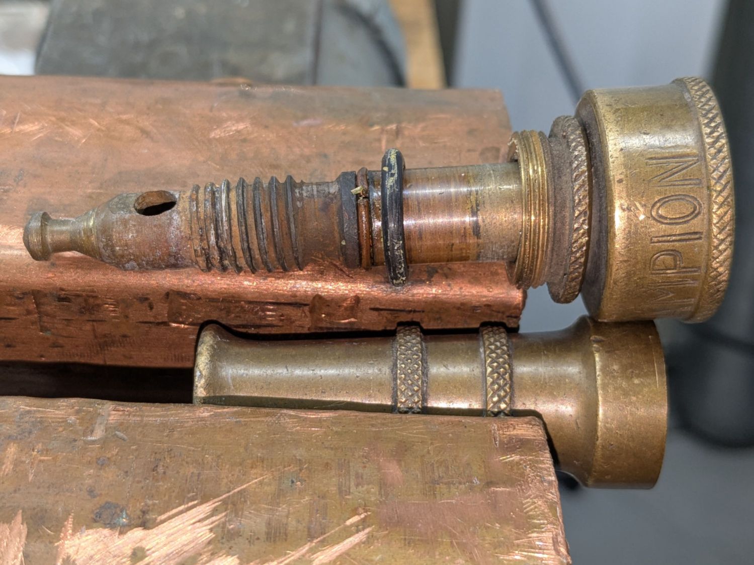
The battered Champion hose nozzle came into play last fall, leaked profusely when turned off, went to a Safe Place for the winter, and recently emerged:
Champion hose nozzle – disassembled
The conical surface (to the right of the tip) must make perfect contact with the edge of a perfect cylindrical hole in the outer shell to shut off the water, which was obviously no longer happening.
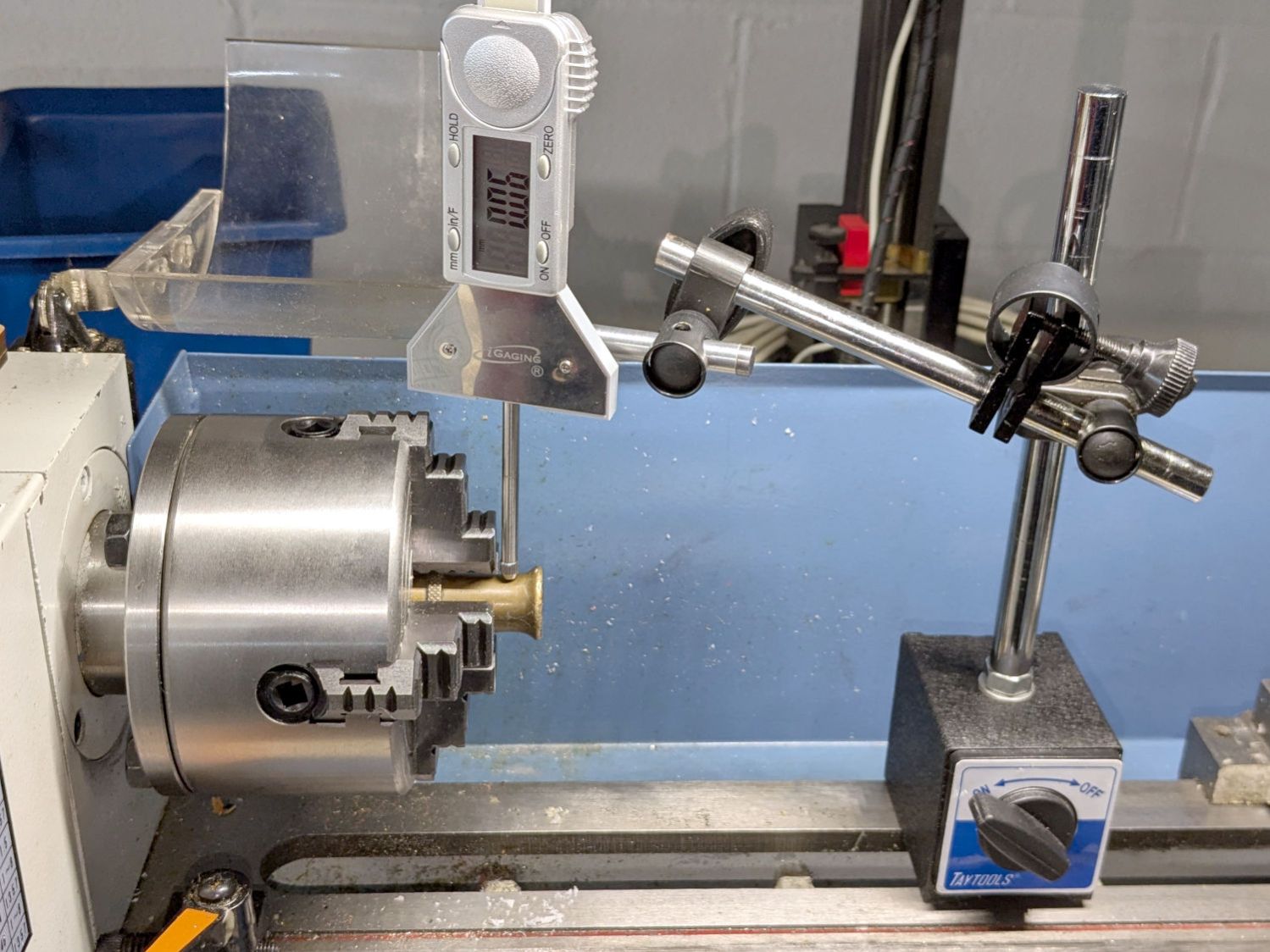
There is no reason why that hole should still be concentric with the outside of the shell, but centering the latter in the four-jaw chuck put the hole within about 0.2 mm of where it should be:
Champion hose nozzle – lathe centering
I defined that to be Close Enough™ and made the hole smooth & concentric with a teeny boring bar and sissy cuts. A drill would likely have worked well enough, too.
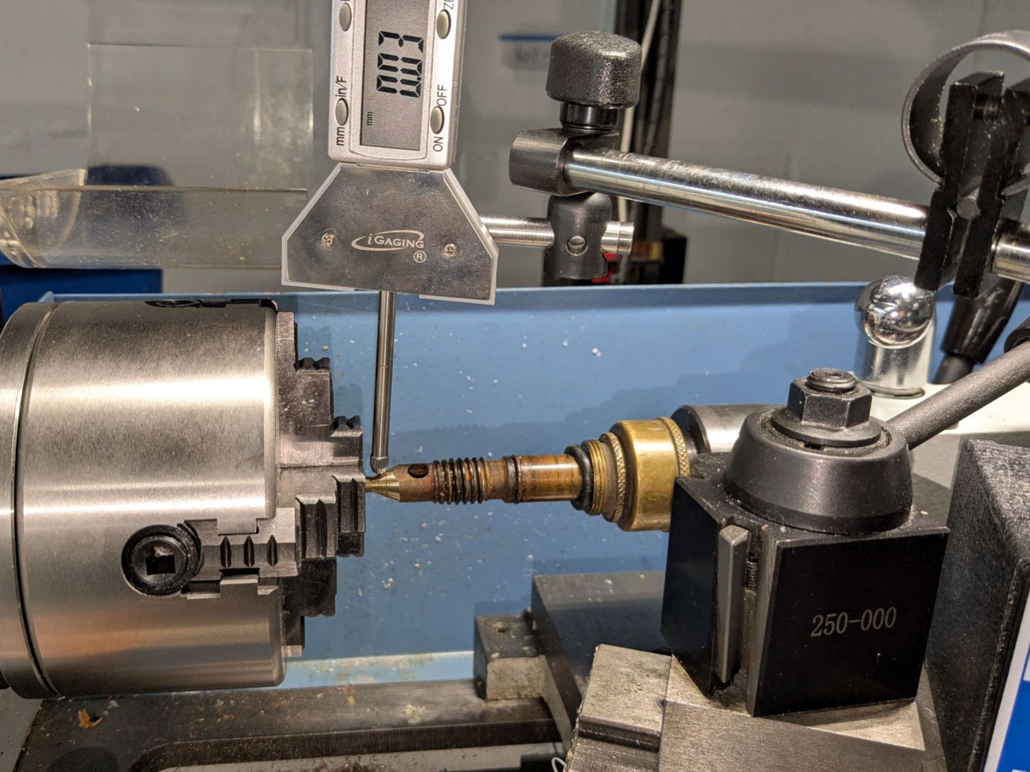
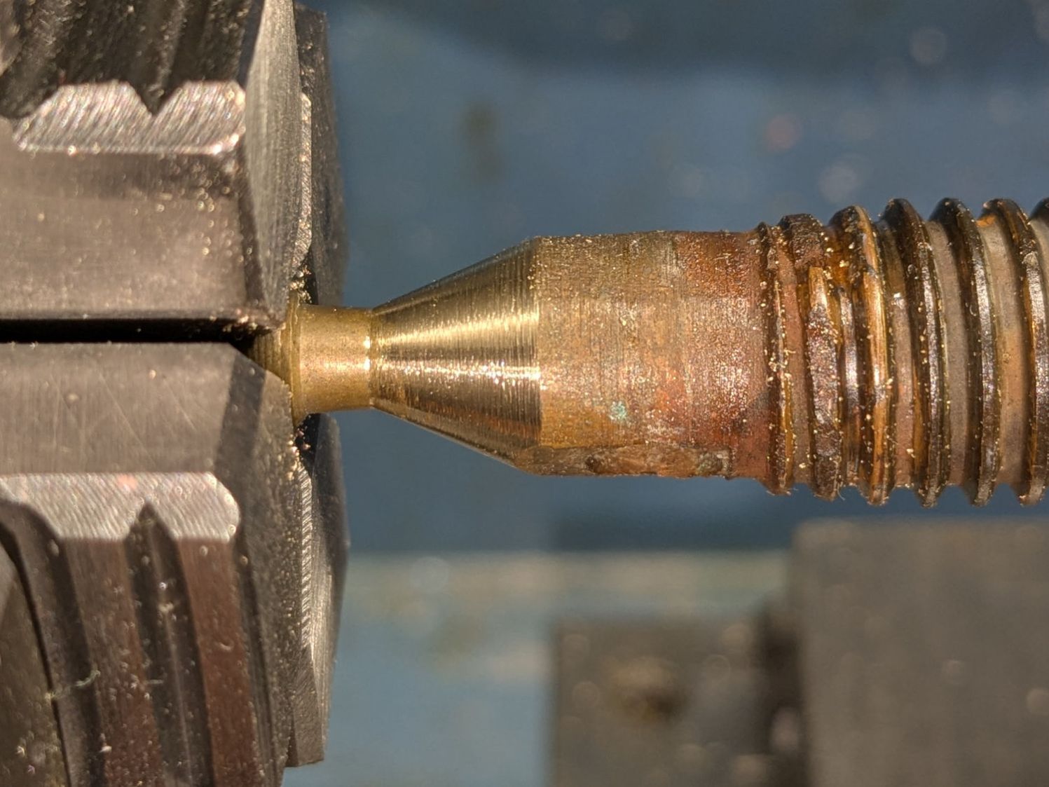
Gently filing the nastiness off the cone showed it wouldn’t suffice, so center it while noting the irregular diameter all around:
Champion hose nozzle – lathe centering cone
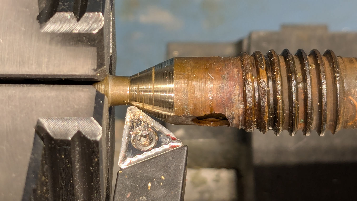
A skim cut revealed the need for more attention:
Champion hose nozzle – scarred cone
Another tenth of a millimeter improved its disposition:
Champion hose nozzle – improved cone
Gentle touchup with a fine file reserved for special occasions may have been a further improvement:
Champion hose nozzle – finish filed
Add a dollop of silicone grease to encourage the shell to turn much more easily on the O-ring, reassemble in reverse order, and top it off with a new hose washer.
A quick test on a reasonably warm day showed the cone met the cylinder poorly enough to consign this nozzle to the brass recycling box.