The Smell of Molten Projects in the Morning

Ed Nisley's Blog: Shop notes, electronics, firmware, machinery, 3D printing, laser cuttery, and curiosities. Contents: 100% human thinking, 0% AI slop.

Tag: M2

Using and tweaking a Makergear M2 3D printer

  • MPCNC: Re-Improved Endstop Switch Mount

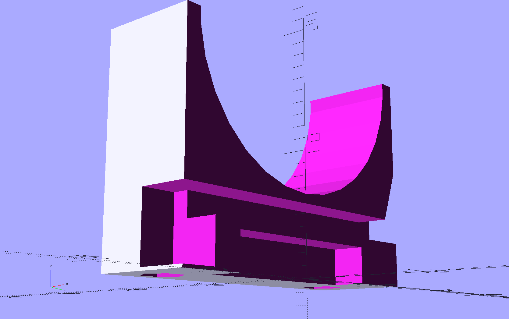
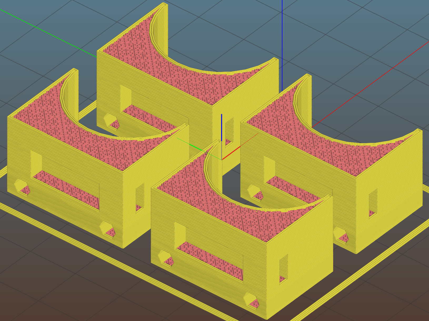
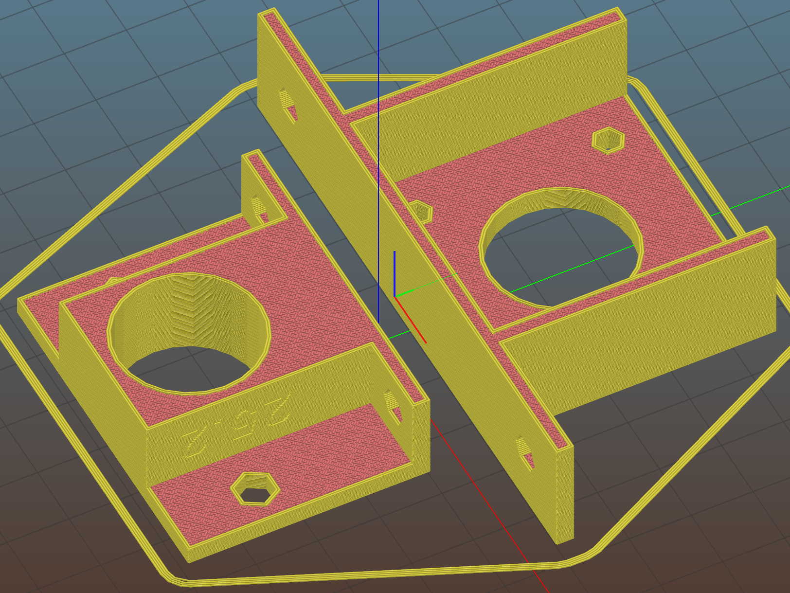
    As part of entombing the endstop PCBs in epoxy, I tweaked the switch mounts to (optionally) eliminate the screw holes and (definitely) rationalize the spacings:

    MPCNC MB Endstop Mount - No screws
    MPCNC MB Endstop Mount – No screws

    The sectioned view shows the cable tie slot neatly centered between the bottom of the switch terminal pit and the EMT rail, now with plenty of meat above the cable tie latch recess. The guide ramp on the other side has a more-better position & angle, too.

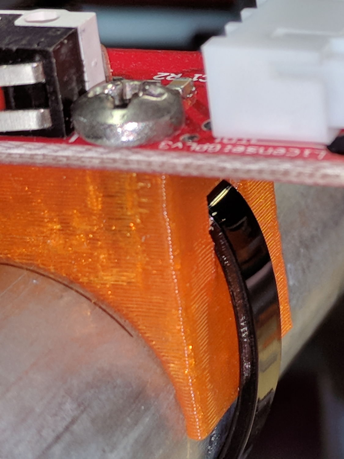
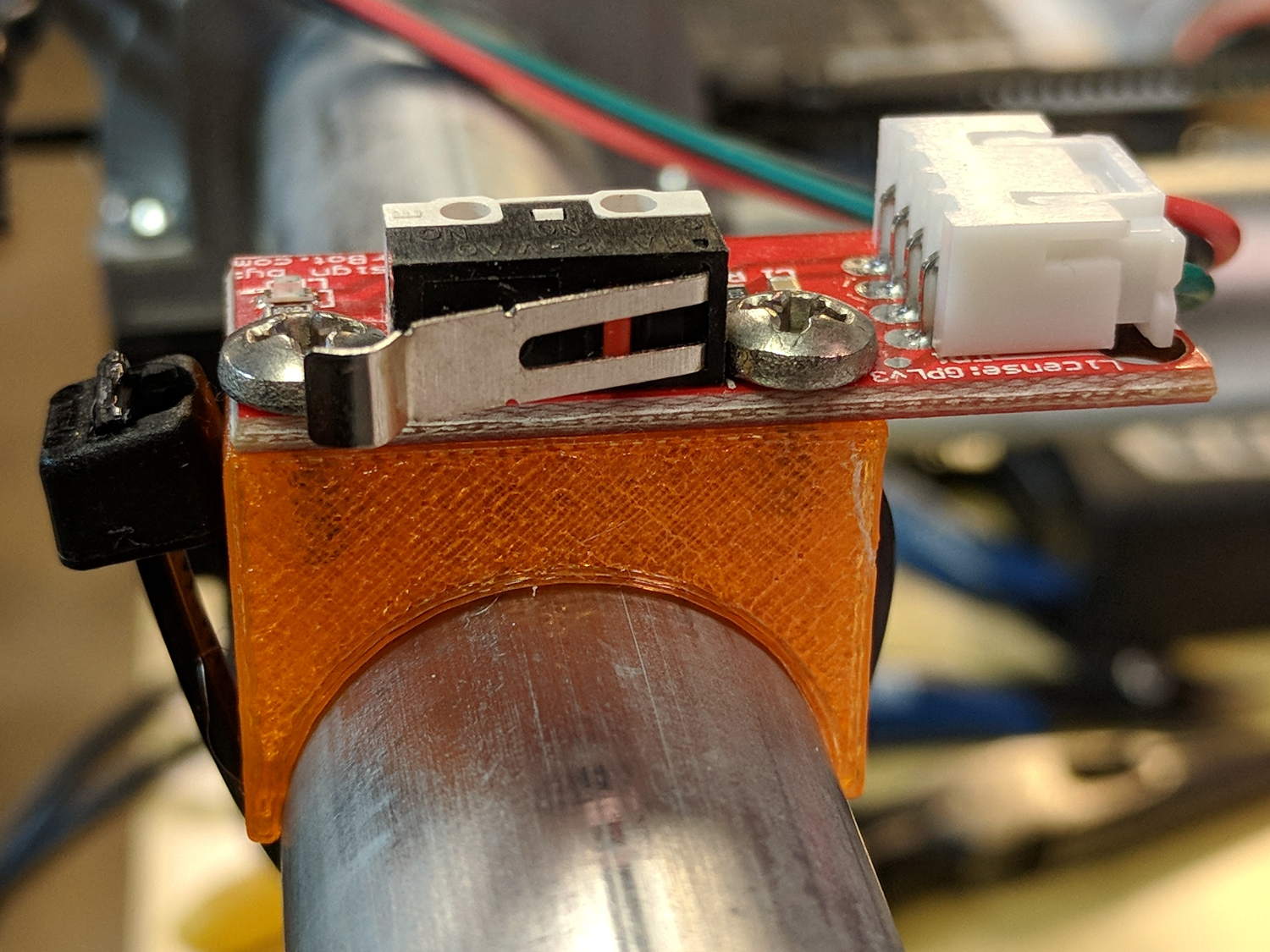
    A trial fit before dabbing on the epoxy:

    MPCNC - Endstop Mount for epoxy coating - trial fit
    MPCNC – Endstop Mount for epoxy coating – trial fit

    The 3M black foam tape works wonderfully well!

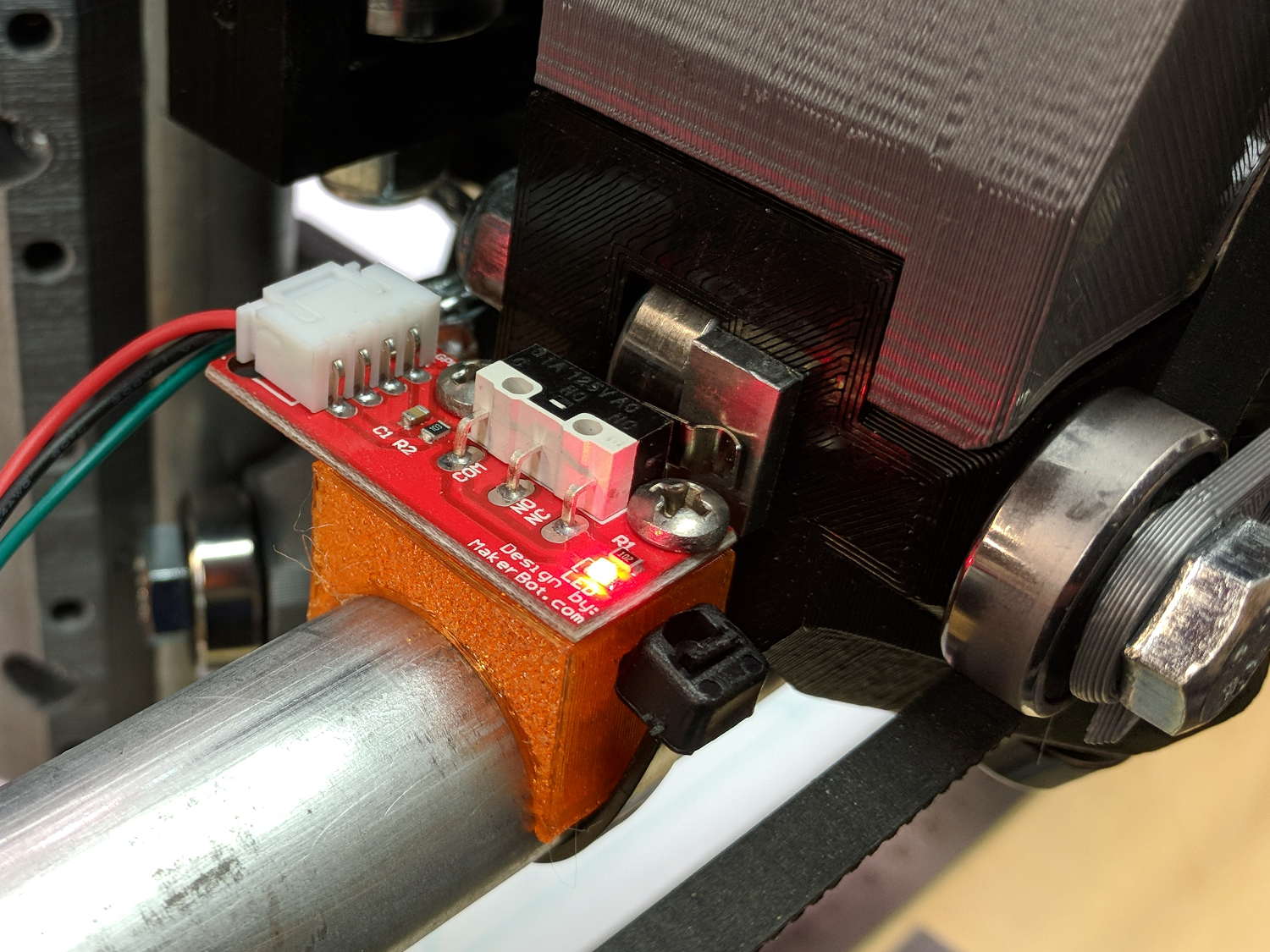
    After the epoxy cures, it’s all good:

    MPCNC - Epoxy-coated Endstop - Installed
    MPCNC – Epoxy-coated Endstop – Installed

    The OpenSCAD source code as a GitHub Gist:

    // MPCNC Endstop Mount for Makerbot PCB on EMT tubing
    // Ed Nisley KE4ZNU – 2017-12-04
    /* [Build Options] */
    Layout = "Show"; // [Build, Show, Block]
    Holes = false; // holes for switch screws
    Section = true; // show internal details
    /* [Extrusion] */
    ThreadThick = 0.25; // [0.20, 0.25]
    ThreadWidth = 0.40; // [0.40]
    function IntegerMultiple(Size,Unit) = Unit * ceil(Size / Unit);
    /* [Hidden] */
    Protrusion = 0.01; // [0.01, 0.1]
    HoleWindage = 0.2;
    ID = 0;
    OD = 1;
    LENGTH = 2;
    /* [Sizes] */
    RailOD = 23.5; // actual rail OD
    SwitchHeight = 8.0; // switch PCB distance from rail OD
    Strap = [5.5,50,2.0]; // nylon strap securing block to rail
    StrapHead = [8.2,3.0,5.5]; // recess for strap ratchet head
    Screw = [2.0,3.6,7.0]; // thread dia, head OD, screw length
    HoleOffset = [2.5,19.0/2]; // PCB mounting holes from PCB edge, rail center
    SwitchClear = [6.0,15,3.0]; // clearance around switch pins
    SwitchOffset = [6.0,0]; // XY center of switch from holes
    StrapHeight = (SwitchHeight – SwitchClear[2])/2; // strap center from rail
    Block = [16.4,26.0,RailOD/2 + SwitchHeight]; // basic block shape
    //- Adjust hole diameter to make the size come out right
    module PolyCyl(Dia,Height,ForceSides=0) { // based on nophead's polyholes
    Sides = (ForceSides != 0) ? ForceSides : (ceil(Dia) + 2);
    FixDia = Dia / cos(180/Sides);
    cylinder(r=(FixDia + HoleWindage)/2,h=Height,$fn=Sides);
    }
    //- Shapes
    // Main block constructed centered on XY with Z=0 at top of rail
    module PCBBlock() {
    difference() {
    translate([-Block[0]/2,-Block[1]/2,-RailOD/2])
    cube(Block,center=false);
    translate([(SwitchOffset[0] + HoleOffset[0] – Block[0]/2),
    SwitchOffset[1],
    (SwitchHeight – SwitchClear[2]/2 + Protrusion/2)])
    cube(SwitchClear + [0,0,Protrusion],center=true);
    if (Holes)
    for (j=[-1,1])
    translate([HoleOffset[0] – Block[0]/2,j*HoleOffset[1],(Block[2]/2 – Screw[LENGTH])])
    rotate(180/6)
    if (true) // true = loose fit
    PolyCyl(Screw[ID],Screw[LENGTH] + Protrusion,6);
    else
    cylinder(d=Screw[ID],h=Screw[LENGTH] + Protrusion,$fn=6);
    translate([0,0,StrapHeight])
    cube(Strap,center=true);
    translate([0, // strap head recess
    (Block[1]/2 – StrapHead[1]/2 + Protrusion),
    StrapHeight – Strap[2]/2 + StrapHead[2]/2])
    cube(StrapHead + [0,Protrusion,0],center=true);
    StrapAngle = atan((StrapHeight + RailOD/4)/Strap[2]); // a reasonable angle
    echo(str("Strap Angle: ",StrapAngle));
    translate([0,-(Block[1]/2 – Strap[2]/(2*sin(StrapAngle))),StrapHeight])
    rotate([StrapAngle,0,0])
    translate([0,-Strap[1]/2,0])
    cube(Strap,center=true);
    if (Section)
    translate([Block[0]/2,0,0])
    cube(Block + [0,2*Protrusion,2*Block[2]],center=true);
    }
    }
    module Mount() {
    difference() {
    translate([0,0,RailOD/2])
    PCBBlock();
    rotate([0,90,0])
    cylinder(d=RailOD,h=3*Block[0],center=true);
    }
    }
    //- Build things
    if (Layout == "Show") {
    Mount();
    color("Yellow",0.5)
    rotate([0,90,0])
    cylinder(d=RailOD,h=3*Block[0],center=true);
    }
    if (Layout == "Block")
    PCBBlock();
    if (Layout == "Build")
    translate([0,0,Block[2]])
    rotate([180,0,0])
    Mount();
  • MPCNC: Endstop Mount, Now With Recess

    There being nothing like a new problem to take your mind off all your old problems, now there’s a cable tie latch recess:

    X min endstop - recessed cable tie latch
    X min endstop – recessed cable tie latch

    A sectioned view of the model shows the layout:

    MPCNC MB Endstop Mount - latch recess
    MPCNC MB Endstop Mount – latch recess

    On the other side, a ramp helps bend the tie toward the MPCNC rail:

    X min endstop - recessed strap
    X min endstop – recessed strap

    Which looks thusly in the realm of applied mathematics:

    MPCNC MB Endstop Mount - strap recess
    MPCNC MB Endstop Mount – strap recess

    I’ll leave the OpenSCAD code to your imagination, because the endstop block turns out to be a bit small for the recesses. Eventually, they need a dust cover and some cleanup.

    So, there!

  • Prototype Board Holder: Now With Mounting Holes and Common Board Sizes

    The folks I’ve been coaching through their plotter build project showed it off at the local MiniMakerFaire this past weekend. Next time around, I’ll insist they secure their circuit boards and use good wiring techniques, so as to avoid destroying more stepper drivers.

    To that end, adding mounting holes to my proto board holder seems in order:

    Proto Board Holder 90x70 - Flange mounting holes - Slic3r preview
    Proto Board Holder 90×70 – Flange mounting holes – Slic3r preview

    The board dimensions now live in an associative array, so you just pick the board name from a Configurator drop-down list:

    /* [Options] */
    
    PCBSelect = "ArdUno"; // ["20x80","40x60","30x70","50x70","70x90","80x120","ArdDuemil","ArdMega","ArdPro","ArdUno","ProtoneerCNC"]
    
    PCB_NAME = 0;
    PCB_DIMENSION = 1;
    
    PCBSizes = [
      ["40x60",[40,60,1.6]],
      ["30x70",[30,70,1.6]],
      ["50x70",[50,70,1.6]],
      ["20x80",[20,80,1.6]],
      ["70x90",[70,90,1.6]],
      ["80x120",[80,120,1.6]],
      ["ArdDuemil",[69,84,1.6]],
      ["ArdMega",[102,53.5,1.6]],
      ["ArdPro",[53,53.5,1.6]],
      ["ArdUno",[69,53.1,1.6]],
      ["ProtoneerCNC",[69,53.1,1.6]],
    ];
    

    Which seems easier than keeping track of the dimensions in comments.

    You can now put the PCB clamp screws and mounting holes on specific corners & sides, allowing oddball locations for Arduino boards with corner cutouts along the right edge:

    Proto Board Holder ArdUno - Slic3r preview
    Proto Board Holder ArdUno – Slic3r preview

    A “selector” notation separates the hole location from the board dimensions & coordinates:

    ScrewSites = [
    //  [-1,1],[1,1],[1,-1],[-1,-1],        // corners
    //  [-1,0],[1,0],[0,1],[0,-1]           // middles
      [-1,1],[-1,-1],[1,0]                  // Arduinos
    ];
    

    Might not be most obvious way, but it works for me. Most of the time, corner clamps seem just fine, so I’m not sure adding the clamp and mounting hole locations to the dimension array makes sense.

    The OpenSCAD source code as a GitHub Gist:

    // Test support frame for proto boards
    // Ed Nisley KE4ZNU – Jan 2017
    // June 2017 – Add side-mount bracket, inserts into bottom
    // 2017-11 – Selectable board sizes, chassis mounting holes
    /* [Options] */
    PCBSelect = "ArdUno"; // ["20×80","40×60","30×70","50×70","70×90","80×120","ArdDuemil","ArdMega","ArdPro","ArdUno","ProtoneerCNC"]
    Layout = "Frame"; // [Frame, Bracket]
    ClampFlange = true; // external flange
    Mounts = true; // frame to chassis screw holes
    Channel = false; // wiring channel cutout
    WasherRecess = false; // cutout around screw head
    /* [Extrusion parameters] */
    ThreadThick = 0.25; // [0.15, 0.20, 0.25]
    ThreadWidth = 0.40;
    function IntegerMultiple(Size,Unit) = Unit * ceil(Size / Unit);
    /* [Hidden] */
    Protrusion = 0.1;
    HoleWindage = 0.2;
    inch = 25.4;
    Tap4_40 = 0.089 * inch;
    Clear4_40 = 0.110 * inch;
    Head4_40 = 0.211 * inch;
    Head4_40Thick = 0.065 * inch;
    Nut4_40Dia = 0.228 * inch;
    Nut4_40Thick = 0.086 * inch;
    Washer4_40OD = 0.270 * inch;
    Washer4_40ID = 0.123 * inch;
    Tap6_32 = 0.106 * inch;
    Clear6_32 = 0.166 * inch;
    Head6_32 = 0.251 * inch;
    Head6_32Thick = 0.097 * inch;
    Nut6_32Dia = 0.312 * inch;
    Nut6_32Thick = 0.109 * inch;
    Washer6_32OD = 0.361 * inch;
    Washer6_32ID = 0.156 * inch;
    ID = 0;
    OD = 1;
    LENGTH = 2;
    //- PCB sizes
    // the list must contain all the selection names as above
    //* [Hidden] */
    PCB_NAME = 0;
    PCB_DIMENSION = 1;
    PCBSizes = [
    ["40×60",[40,60,1.6]],
    ["30×70",[30,70,1.6]],
    ["50×70",[50,70,1.6]],
    ["20×80",[20,80,1.6]],
    ["70×90",[70,90,1.6]],
    ["80×120",[80,120,1.6]],
    ["ArdDuemil",[69,84,1.6]],
    ["ArdMega",[102,53.5,1.6]],
    ["ArdPro",[53,53.5,1.6]],
    ["ArdUno",[69,53.1,1.6]],
    ["ProtoneerCNC",[69,53.1,1.6]],
    ];
    PCBIndex = search([PCBSelect],PCBSizes)[0];
    PCBSize = PCBSizes[PCBIndex][PCB_DIMENSION];
    //echo(str("PCB Size Table: ",PCBSizes));
    //echo(str("PCB Select: ",PCBSelect));
    //echo(str("PCB Index: ",PCBIndex));
    echo(str("PCB Size: ",PCBSize));
    /* [Sizes] */
    WallThick = 4.0; // basic frame structure
    FrameHeight = 10.0;
    /* [Hidden] */
    Insert = [3.9,4.6,5.8];
    PCBShelf = 1.0; // width of support rim under PCB
    Clearance = 1*[ThreadWidth,ThreadWidth,0]; // around PCB on all sides
    ScrewOffset = ThreadWidth + Insert[OD]/2; // beyond PCB edges
    echo(str("Screw offset: ",ScrewOffset));
    /* [Screw Selectors] */
    // ij selectors for PCB clamp screw holes: -1/0/1 = left/center/right , bottom/center/top
    ScrewSites = [
    // [-1,1],[1,1],[1,-1],[-1,-1], // corners
    // [-1,0],[1,0],[0,1],[0,-1] // middles
    [-1,1],[-1,-1],[1,0] // Arduinos
    ];
    // ij selectors for frame mounting holes
    MountSites = [
    [0,-1],[0,1],
    // [-1,0],[1,0]
    ];
    function ScrewAngle(ij) = (ij[0]*ij[1]) ? ij[0]*ij[1]*15 : ((!ij[1]) ? 30 : 0); // align screw sides
    OAHeight = FrameHeight + Clearance[2] + PCBSize[2]; // total frame height
    echo(str("OAH: ",OAHeight));
    BossOD = 2*Washer4_40OD; // make bosses oversized for washers
    FlangeExtension = 4.0 + Washer6_32OD/2 – WallThick; // beyond frame structure
    FlangeThick = IntegerMultiple(2.0,ThreadThick); // plate under frame
    Flange = PCBSize
    + 2*[ScrewOffset,ScrewOffset,0]
    + [BossOD,BossOD,0]
    + [2*FlangeExtension,2*FlangeExtension,(FlangeThick – PCBSize[2])]
    ;
    FlangeRadius = BossOD/4;
    echo(str("Flange: ",Flange));
    NumSides = 4*5;
    WireChannel = [Flange[0],15.0,3.0 + PCBSize[2]]; // ad-hoc wiring cutout
    WireChannelOffset = [
    Flange[0]/2,0,(FrameHeight + PCBSize[2] – WireChannel[2]/2)
    ];
    //- Adjust hole diameter to make the size come out right
    module PolyCyl(Dia,Height,ForceSides=0) { // based on nophead's polyholes
    Sides = (ForceSides != 0) ? ForceSides : (ceil(Dia) + 2);
    FiiDia = Dia / cos(180/Sides);
    cylinder(r=(FiiDia + HoleWindage)/2,h=Height,$fn=Sides);
    }
    //- Build things
    if (Layout == "Frame")
    difference() {
    union() { // body block
    translate([0,0,OAHeight/2])
    cube(PCBSize + Clearance + [2*WallThick,2*WallThick,FrameHeight],center=true);
    for (ij = ScrewSites) // screw bosses
    if (ij[0] != 0 || ij[1] != 0)
    translate([ij[0]*(PCBSize[0]/2 + ScrewOffset),
    ij[1]*(PCBSize[1]/2 + ScrewOffset),
    0])
    cylinder(d=BossOD,h=OAHeight,$fn=NumSides);
    if (ClampFlange) // flange for work holder & mounting screw holes
    linear_extrude(height=Flange[2])
    hull()
    for (i=[-1,1], j=[-1,1]) {
    translate([i*(Flange[0]/2 – FlangeRadius),j*(Flange[1]/2 – FlangeRadius)])
    circle(r=FlangeRadius,$fn=NumSides); // convenient rounding size
    }
    }
    for (ij = ScrewSites) { // screw position indeies
    if (ij[0] != 0 || ij[1] != 0) {
    translate([ij[0]*(PCBSize[0]/2 + ScrewOffset),
    ij[1]*(PCBSize[1]/2 + ScrewOffset),
    -Protrusion])
    rotate(ScrewAngle(ij))
    PolyCyl(Clear4_40,(OAHeight + 2*Protrusion),6); // screw clearance holes
    translate([ij[0]*(PCBSize[0]/2 + ScrewOffset),
    ij[1]*(PCBSize[1]/2 + ScrewOffset),
    -Protrusion])
    rotate(ScrewAngle(ij))
    PolyCyl(Insert[OD],OAHeight – PCBSize[2] – 3*ThreadThick + Protrusion,6); // inserts
    if (WasherRecess)
    translate([ij[0]*(PCBSize[0]/2 + ScrewOffset),
    ij[1]*(PCBSize[1]/2 + ScrewOffset),
    OAHeight – PCBSize[2]])
    PolyCyl(1.2*Washer4_40OD,(PCBSize[2] + Protrusion),NumSides); // optional washer recess
    }
    }
    if (Mounts)
    for (ij = MountSites)
    translate([ij[0]*(Flange[0]/2 – Washer6_32OD/2),ij[1]*(Flange[1]/2 – Washer6_32OD/2),-Protrusion])
    rotate(ScrewAngle(ij))
    PolyCyl(Clear6_32,(Flange[2] + 2*Protrusion),6);
    translate([0,0,OAHeight/2]) // through hole below PCB
    cube(PCBSize – 2*[PCBShelf,PCBShelf,0] + [0,0,2*OAHeight],center=true);
    translate([0,0,(OAHeight – (PCBSize[2] + Clearance[2])/2 + Protrusion/2)]) // PCB pocket on top
    cube(PCBSize + Clearance + [0,0,Protrusion],center=true);
    if (Channel)
    translate(WireChannelOffset) // opening for wires from bottom side
    cube(WireChannel + [0,0,Protrusion],center=true);
    }
    // Add-on bracket to hold smaller PCB upright at edge
    PCB2Insert = [3.0,4.9,4.1];
    PCB2OC = 45.0;
    if (Layout == "Bracket")
    difference() {
    hull() // frame body block
    for (i=[-1,1]) // bosses around screws
    translate([i*(PCBSize[0]/2 + ScrewOffset),0,0])
    cylinder(r=Washer4_40OD,h=OAHeight,$fn=NumSides);
    for (i=[-1,1]) // frame screw holes
    translate([i*(PCBSize[0]/2 + ScrewOffset),0,-Protrusion])
    rotate(i*180/(2*6))
    PolyCyl(Clear4_40,(OAHeight + 2*Protrusion),6);
    for (i=[-1,1]) // PCB insert holes
    translate([i*PCB2OC/2,(Washer4_40OD + Protrusion),OAHeight/2])
    rotate([90,0,0])
    cylinder(d=PCB2Insert[OD],h=2*(Washer4_40OD + Protrusion),$fn=6);
    }
  • Mostly Printed CNC: Endstop Mount

    Being a big fan of having a CNC machine know where it is, adding endstops (pronounded “home switches” in CNC parlance) to the Mostly Printed CNC axes seemed like a good idea:

    MPCNC - X min endstop - actuator view
    MPCNC – X min endstop – actuator view

    All the mounts I could find fit bare microswitches of various sizes or seemed overly complex & bulky for what they accomplished. Rather than fiddle with screws and nut traps / inserts, a simple cable tie works just fine and makes the whole affair much smaller. Should you think cable ties aren’t secure enough, a strip of double stick tape will assuage your doubts.

    A snippet of aluminum sheet moves the switch trip point out beyond the roller’s ball bearing:

    MPCNC - X min endstop
    MPCNC – X min endstop

    I’m not convinced homing the Z axis at the bottom of its travel is the right thing to do, but it’s a start:

    MPCNC - Z min endstop
    MPCNC – Z min endstop

    Unlike the stationary X and Y axes, the MPCNC’s Z axis rails move vertically in the middle block assembly; the switch moves downward on the rail until the actuator hits the block.

    Perforce, the tooling mounted on the Z axis must stick out below the bottom of the tool carrier, which means the tool will hit the table before the switch hits the block. There should also be a probe input to support tool height setting.

    The first mount fit perfectly, so I printed four more in one pass:

    MPCNC MB Endstop Mounts - Slic3r preview
    MPCNC MB Endstop Mounts – Slic3r preview

    All three endstops plug into the RAMPS board, leaving the maximum endstop connections vacant:

    MPCNC - RAMPS min endstop positions
    MPCNC – RAMPS min endstop positions

    Obviously, bare PCBs attached to the rails in mid-air aren’t compatible with milling metal, which I won’t be doing for quite a while. The electronic parts long to be inside enclosures with ventilation and maybe dust filtering, but …

    The switches operate in normally open mode, closing when tripped. That’s backwards, of course, and defined to be completely irrelevant in the current context.

    Seen from a high level, these switches set the absolute “machine coordinate system” origin, so the firmware travel limits can take effect. Marlin knows nothing about coordinate systems, but GRBL does: it can touch off to a fixture origin and generally do the right thing.

    The OpenSCAD source code as a GitHub Gist:

    // Tour Easy Fairing Endstop Mount for Makerbot PCB
    // Ed Nisley KE4ZNU – 2017-11-07
    /* [Build Options] */
    Layout = "Build"; // [Build, Show, Block]
    Section = false; // show internal details
    /* [Extrusion] */
    ThreadThick = 0.25; // [0.20, 0.25]
    ThreadWidth = 0.40; // [0.40]
    function IntegerMultiple(Size,Unit) = Unit * ceil(Size / Unit);
    /* [Hidden] */
    Protrusion = 0.01; // [0.01, 0.1]
    HoleWindage = 0.2;
    ID = 0;
    OD = 1;
    LENGTH = 2;
    /* [Sizes] */
    RailOD = 23.5;
    Screw = [3.4,6.8,8.0]; // thread dia, head OD, screw length
    HoleOffset = [2.5,19.0/2]; // PCB mounting holes from PCB edge, rail center
    SwitchClear = [6.0,15,3.0]; // clearance around switch pins
    SwitchOffset = [6.0,0]; // center of switch from holes
    Strap = [5.5,50,2.0]; // nylon strap securing block to rail
    Block = [16.4,26.0,RailOD/2 + SwitchClear[2] + Strap[2] + 6*ThreadThick]; // basic block shape
    //- Adjust hole diameter to make the size come out right
    module PolyCyl(Dia,Height,ForceSides=0) { // based on nophead's polyholes
    Sides = (ForceSides != 0) ? ForceSides : (ceil(Dia) + 2);
    FixDia = Dia / cos(180/Sides);
    cylinder(r=(FixDia + HoleWindage)/2,h=Height,$fn=Sides);
    }
    //- Shapes
    module PCBBlock() {
    difference() {
    cube(Block,center=true);
    translate([(SwitchOffset[0] + HoleOffset[0] – Block[0]/2),SwitchOffset[1],(Block[2] – SwitchClear[2] + Protrusion)/2])
    cube(SwitchClear + [0,0,Protrusion],center=true);
    for (j=[-1,1])
    translate([HoleOffset[0] – Block[0]/2,j*HoleOffset[1],(Block[2]/2 – Screw[LENGTH])])
    rotate(180/6)
    if (false) // true = loose fit
    PolyCyl(Screw[ID],Screw[LENGTH] + Protrusion,6);
    else
    cylinder(d=Screw[ID],h=Screw[LENGTH] + Protrusion,$fn=6);
    translate([0,0,Block[2]/2 – SwitchClear[2] – Strap[2]/2 – 3*ThreadThick])
    cube(Strap,center=true);
    if (Section)
    translate([Block[0]/2,0,0])
    cube(Block + [0,2*Protrusion,2*Protrusion],center=true);
    }
    }
    module Mount() {
    difference() {
    translate([0,0,Block[2]/2])
    PCBBlock();
    rotate([0,90,0])
    cylinder(d=RailOD,h=3*Block[0],center=true);
    }
    }
    //- Build things
    if (Layout == "Show") {
    Mount();
    color("Yellow",0.5)
    rotate([0,90,0])
    cylinder(d=RailOD,h=3*Block[0],center=true);
    }
    if (Layout == "Block")
    PCBBlock();
    if (Layout == "Build")
    translate([0,0,Block[2]/2])
    rotate([0,-90,0])
    Mount();
  • NEMA17 Motor and Bearing Mounts

    As part of coaching a student (and his father!) on their incredibly ambitious build-a-plotter-from-scratch project, I suggested stealing using HP’s grit-wheel paper drive, rather than fiddling with guide rods to move either the pen carrier or the entire paper platform. Dremel sanding drums seem about the right size and they had an 8 mm shaft harvested from a defunct printer, so a pair of mounts moves the project along:

    NEMA17 and Bearing Mounts - Slic3r preview
    NEMA17 and Bearing Mounts – Slic3r preview

    The motor mount code is a hack job from my old NEMA17 mount and the code has a lot not to like. The bearing mount puts the bearing on the proper centerline using brute force copypasta and depends on friction to hold it in place. The two models should be integrated into the same file, the shaft centerline shouldn’t involve the printed thread width, and blah blah blah:

    NEMA17 motor and bearing mounts
    NEMA17 motor and bearing mounts

    I had him turn the shaft adapter from an aluminum rod in the mini-lathe: he’s hooked.

    The OpenSCAD source code as a GitHub Gist:

    // Ball bearing mount
    // Ed Nisley KE4ZNU 2017-10-09
    //– Extrusion parameters
    ThreadThick = 0.20;
    ThreadWidth = 0.40;
    HoleWindage = 0.2; // enlarge hole dia by this amount
    function IntegerMultiple(Size,Unit) = Unit * ceil(Size / Unit);
    Protrusion = 0.1; // make holes look good and joints intersect properly
    //– Useful sizes
    inch = 25.4;
    Tap10_32 = 0.159 * inch;
    Clear10_32 = 0.190 * inch;
    Head10_32 = 0.373 * inch;
    Head10_32Thick = 0.110 * inch;
    Nut10_32Dia = 0.433 * inch;
    Nut10_32Thick = 0.130 * inch;
    // Bearing sizes
    ID = 0;
    OD = 1;
    LENGTH = 2;
    Bearing = [8.0,22.0,7.0];
    ShaftHeight = IntegerMultiple(25.2,ThreadWidth); // arbitrary or copied from motor mount
    WallThick = 3.0;
    //– Mount Sizes
    MountSize = Bearing[OD] + 2*WallThick;
    BaseThick = max(WallThick,ShaftHeight – MountSize/2); // baseplate
    StandBoltHead = IntegerMultiple(Head10_32,2); // bolt head rounded up
    StandBoltClear = 1.25 * StandBoltHead;
    StandBoltOC = IntegerMultiple(MountSize + StandBoltClear,2);
    StandLength = StandBoltOC + StandBoltClear;
    StandThick = StandBoltClear + WallThick;
    StandHeight = MountSize + BaseThick;
    Cutout = (StandLength – MountSize)/2;
    echo(str("Stand Base: ",StandLength," x ",StandThick," x ",BaseThick));
    echo(str("Stand Bolt OC: ",StandBoltOC));
    echo(str("Shaft Height:",ShaftHeight));
    //———————-
    // Useful routines
    module PolyCyl(Dia,Height,ForceSides=0) { // based on nophead's polyholes
    Sides = (ForceSides != 0) ? ForceSides : (ceil(Dia) + 2);
    FixDia = Dia / cos(180/Sides);
    cylinder(r=(FixDia + HoleWindage)/2,
    h=Height,
    $fn=Sides);
    }
    //———————-
    // Put it together
    module BearingMount() {
    difference() {
    translate([BaseThick/2,0,StandThick/2])
    cube([StandHeight,StandLength,StandThick],center=true);
    translate([0,0,-Protrusion])
    PolyCyl(Bearing[OD],(StandThick + 2*Protrusion));
    for (j=[-1,1]) // cutouts over bolts
    translate([-(StandHeight/2 – ShaftHeight + WallThick),
    j*(StandLength/2 – Cutout/2 + Protrusion/2),
    (WallThick + StandThick/2)])
    cube([StandHeight,
    Cutout + Protrusion,
    StandThick],center=true);
    for (j=[-1,1]) // stand bolt holes – base
    translate([(MountSize/2 – Protrusion),
    j*StandBoltOC/2,
    WallThick + StandBoltClear/2])
    rotate([0,90,0])
    rotate(180/6)
    PolyCyl(Clear10_32,BaseThick + 2*Protrusion,6);
    for (j=[-1,1]) // stand bolt holes – back
    translate([0,j*StandBoltOC/2,-Protrusion])
    rotate(180/6)
    PolyCyl(Clear10_32,StandThick + 2*Protrusion,6);
    translate([0,-(MountSize/2 – ThreadWidth/2),(StandThick – WallThick)/2 + WallThick])
    rotate([90,180,0])
    linear_extrude(ThreadWidth,convexity=10)
    text(text=str(ShaftHeight),size=6,spacing=1.20,font="Arial",halign="center",valign="center");
    }
    }
    //———————-
    // Build it
    BearingMount();
    // NEMA 17 stepper mount
    // Ed Nisley KE4ZNU August 2011
    // Tweaked & thinned 2017-10-09
    //– Extrusion parameters
    ThreadThick = 0.25;
    ThreadWidth = 0.4;
    HoleWindage = 0.3; // enlarge hole dia by this amount
    function IntegerMultiple(Size,Unit) = Unit * ceil(Size / Unit);
    Protrusion = 0.1; // make holes look good and joints intersect properly
    //– Useful sizes
    inch = 25.4;
    Tap10_32 = 0.159 * inch;
    Clear10_32 = 0.190 * inch;
    Head10_32 = 0.373 * inch;
    Head10_32Thick = 0.110 * inch;
    Nut10_32Dia = 0.433 * inch;
    Nut10_32Thick = 0.130 * inch;
    NEMA17_ShaftDia = 5.0;
    NEMA17_ShaftLength = 24.0;
    NEMA17_PilotDia = 0.866 * inch;
    NEMA17_PilotLength = 0.080 * inch;
    NEMA17_BCD = 1.725 * inch;
    NEMA17_BoltDia = 3.5;
    NEMA17_BoltOC = 1.220 * inch;
    //– Mount Sizes
    MountWidth = IntegerMultiple(NEMA17_BCD,ThreadWidth); // use BCD for motor clearance
    MountThick = IntegerMultiple(4.0,ThreadThick); // for stiffness
    MountBoltDia = 3.0;
    StandThick = 3.0; // baseplate
    StrutThick = IntegerMultiple(3.0,ThreadWidth); // sides holding motor mount
    UprightLength = MountWidth + 2*StrutThick;
    StandBoltHead = IntegerMultiple(Head10_32,5); // bolt head rounded up
    StandBoltOC = IntegerMultiple(UprightLength + 2*StandBoltHead,5);
    StandLength = StandBoltOC + 2*StandBoltHead;
    StandWidth = 2*StandBoltHead;
    StandBoltClear = (StandLength – UprightLength)/2; // flat around bolt head
    MotorRecess = StandWidth – MountThick;
    ShaftHeight = IntegerMultiple(StandThick + MountWidth/2,ThreadWidth);
    echo(str("Stand Base: ",StandLength," x ",StandWidth," x ",StandThick));
    echo(str("Stand Bolt OC: ",StandBoltOC));
    echo(str("Shaft Height:",ShaftHeight));
    echo(str("Strut Thick: ",StrutThick));
    //———————-
    // Useful routines
    module PolyCyl(Dia,Height,ForceSides=0) { // based on nophead's polyholes
    Sides = (ForceSides != 0) ? ForceSides : (ceil(Dia) + 2);
    FixDia = Dia / cos(180/Sides);
    cylinder(r=(FixDia + HoleWindage)/2,
    h=Height,
    $fn=Sides);
    }
    //———————-
    // Model
    module MotorMount() {
    difference() {
    translate([StandThick/2,0,StandWidth/2])
    cube([(MountWidth + StandThick),StandLength,StandWidth],center=true);
    translate([-Protrusion/2,0,StandWidth – (MotorRecess – Protrusion)/2])
    cube([(MountWidth + Protrusion),MountWidth,(MotorRecess + Protrusion)],center=true);
    translate([0,0,-Protrusion]) // pilot hole
    PolyCyl(NEMA17_PilotDia,(MountThick + 2*Protrusion));
    for (i=[-1,1]) // motor bolt holes
    for (j=[-1,1])
    translate([i*NEMA17_BoltOC/2,j*NEMA17_BoltOC/2,-Protrusion])
    PolyCyl(MountBoltDia,(MountThick + 2*Protrusion),6);
    for (j=[-1,1]) // cutouts over bolts
    translate([-Protrusion/2,
    j*((StandLength – StandBoltClear)/2 + Protrusion/2),
    StandWidth/2])
    cube([(MountWidth + Protrusion),
    (StandBoltClear + Protrusion),
    (StandWidth + 2*Protrusion)],center=true);
    for (j=[-1,1]) // stand bolt holes
    translate([(MountWidth/2 – Protrusion),j*StandBoltOC/2,StandWidth/2])
    rotate([0,90,0])
    rotate(180/6)
    PolyCyl(Clear10_32,StandThick + 2*Protrusion,6);
    translate([0,-(UprightLength/2 – ThreadWidth/2),StandWidth/2])
    rotate([90,180,0])
    linear_extrude(ThreadWidth,convexity=10)
    text(text=str(ShaftHeight),size=6,spacing=1.20,font="Arial",halign="center",valign="center");
    }
    }
    //———————-
    // Build it
    MotorMount();
  • More Tommy Bar Handles

    Having used a nail for far too long, this is a definite step up for my machinist vises:

    Tommy Bar - machinist vise
    Tommy Bar – machinist vise

    The vise knob has a hole just barely passing a length of 3.4 mm = 9/64 inch mild steel rod from the Small Box o’ Cutoffs.

    While I was at it, I made a handle for the parallel jaw clamps:

    Tommy Bar - parallel jaw clamp
    Tommy Bar – parallel jaw clamp

    Those knobs pass a 3.0 mm = 1/8 inch rod, similarly sourced. Inexplicably, one clamp expected no more than a 7/64 inch rod; a brief introduction to Mr Drill Press persuaded it concerning the error of its ways.

    I should have made the handles distinctively different, because they’ll get mixed up in the box of vises & clamps. Next time, fer shure!

    The Tommy Bar handles use the same solid model as the Sherline Tommy Bars, with hole diameters as noted. Cyan PETG is definitely easier on the eye than red PLA, although it does fade into the background clutter around here.

  • Hydrant Wrench

    Just because I can:

    Fire Hydrant Wrench
    Fire Hydrant Wrench

    The Slic3r preview shows a bit more detail:

    Hydrant Wrench - Slic3r preview
    Hydrant Wrench – Slic3r preview

    Even an inch-thick handle wouldn’t have enough mojo for the task.

    Wikipedia has the equations you need to go from the easily measured “height” (vertex to opposite side) dimension to the pentagon’s “outside radius”, which equals the radius of the circumscribed circle needed by OpenSCAD.

    The OpenSCAD source code as a GitHub Gist:

    // Hydrant Wrench
    // Ed Nisley KE4ZNU – September 2017
    /* [Extrusion] */
    ThreadThick = 0.25; // [0.20, 0.25]
    ThreadWidth = 0.40; // [0.40]
    function IntegerMultiple(Size,Unit) = Unit * ceil(Size / Unit);
    Protrusion = 0.01; // [0.01, 0.1]
    HoleWindage = 0.2;
    //- Sizes
    /* [Dimensions] */
    NumFlats = 5; // this is not a variable for this geometry!
    Height = 39.0; // pentagon flat-to-vertex measurement
    Side = Height / 1.539;
    echo(str("Side:",Side));
    Radius = Side / 1.176;
    echo(str("Radius: ",Radius));
    WrenchDia = 2*Radius; // pentagon circumcircle diameter
    echo(str("Wrench dia:",WrenchDia));
    JawWidth = 10.0;
    JawOD = 2*JawWidth + WrenchDia;
    echo(str("Jaw OD: ",JawOD));
    WrenchThick = 5.0;
    HandleLength = 2*JawOD;
    HandleWidth = 25.0;
    //- Build things
    difference() {
    linear_extrude(height=WrenchThick,convexity=4) {
    hull() { // taper wrench body to handle
    circle(d=JawOD);
    translate([0.75*JawOD,0,0])
    circle(d=HandleWidth);
    }
    hull() { // handle
    translate([0.75*JawOD,0,0])
    circle(d=HandleWidth);
    translate([HandleLength,0,0])
    circle(d=HandleWidth);
    }
    }
    translate([0,0,-Protrusion])
    rotate(180/NumFlats)
    cylinder(d=WrenchDia,h=(WrenchThick + 2*Protrusion),$fn=NumFlats);
    translate([WrenchDia,0,WrenchThick – 3*ThreadThick])
    linear_extrude(3*ThreadThick + Protrusion,convexity=10)
    text(text=str("Fire Hydrant!"),size=8,spacing=1.20,font="Arial",halign="left",valign="center");
    }

    Sorry ’bout that … had to do it.