Ed Nisley's Blog: Shop notes, electronics, firmware, machinery, 3D printing, laser cuttery, and curiosities. Contents: 100% human thinking, 0% AI slop.
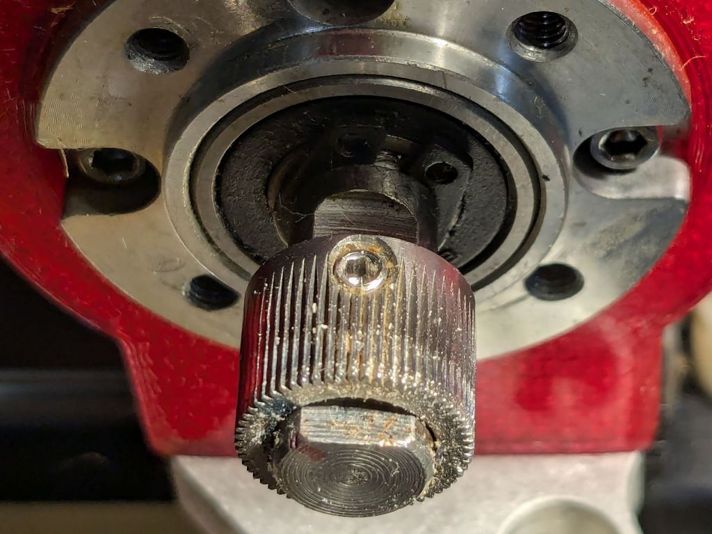
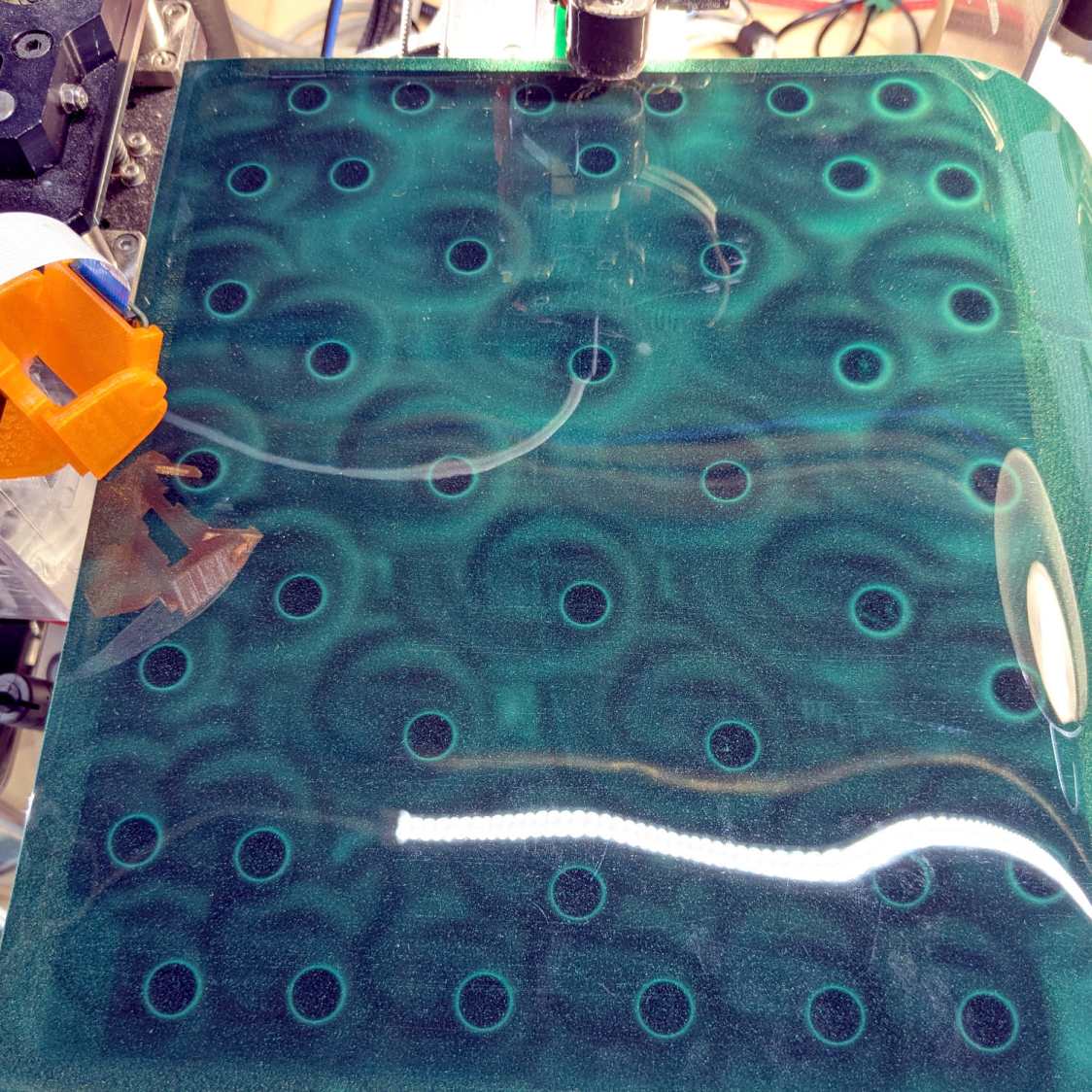
AFAICT, the Makergear M2’s filament drive gear has been in the same place on the motor shaft since I set it up nearly five years ago:
Makergear M2 – original filament drive pulley position
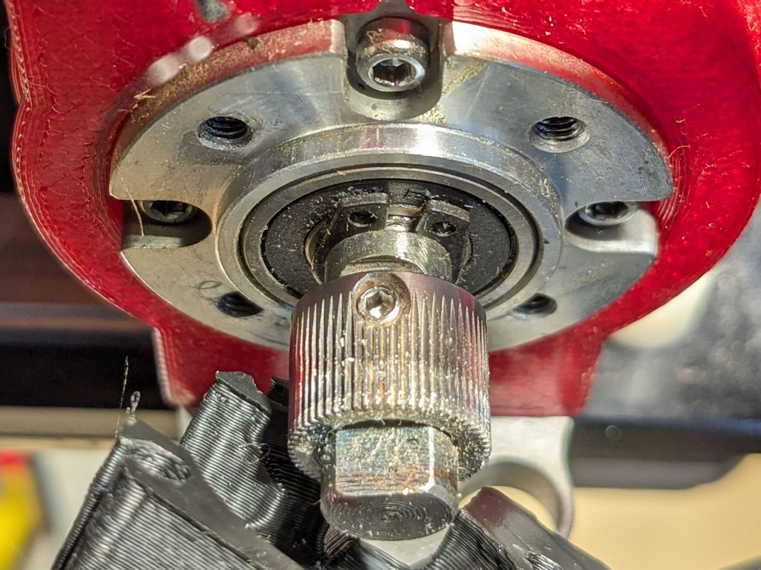
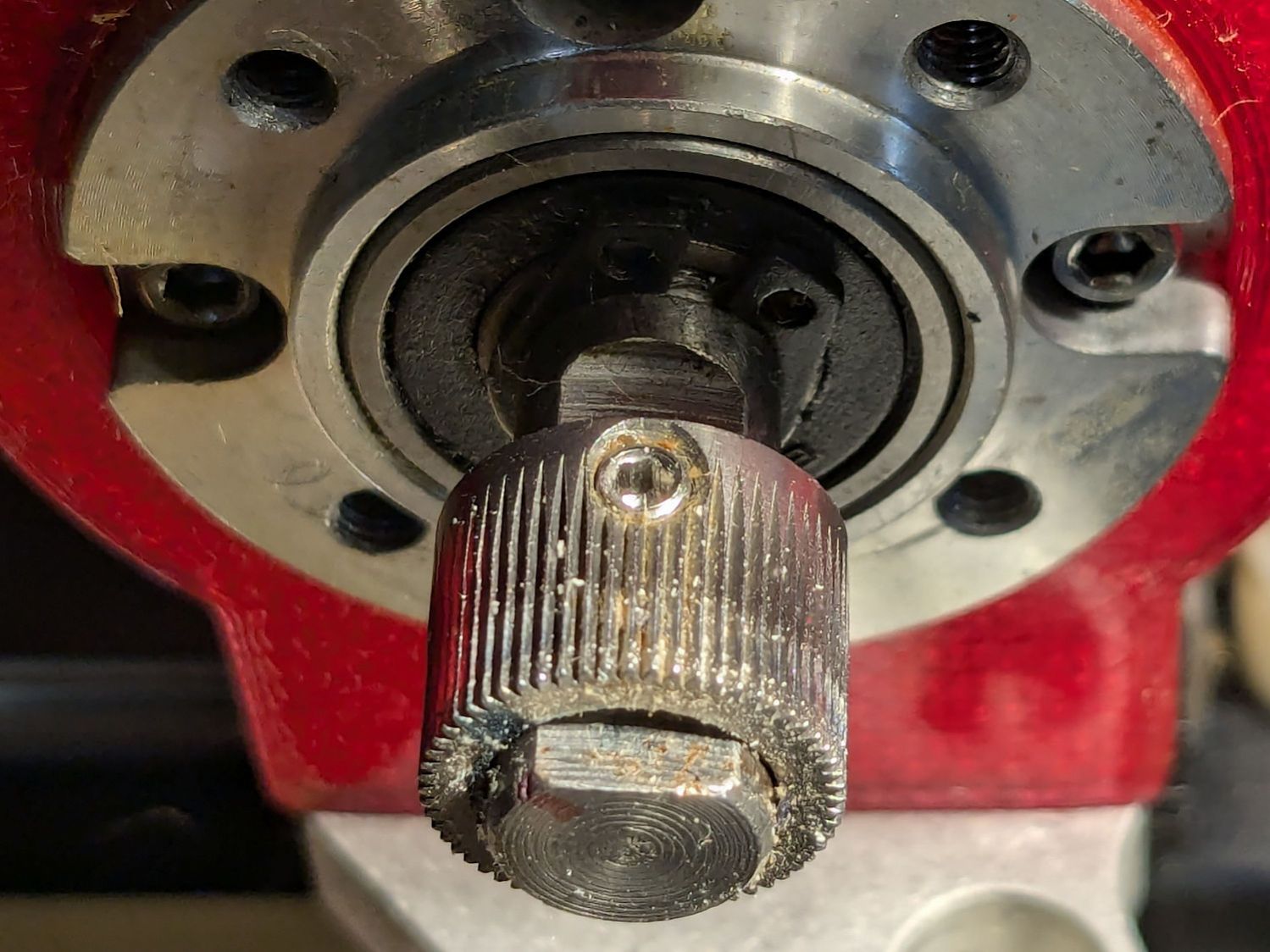
The filament rides along the white trail close to the front of the gear. This worked fine with PETG, but TPU occasionally squeezed out through the small gap toward the front of the extruder, so I moved the gear a few millimeters forward:
Makergear M2 – improved filament drive pulley position
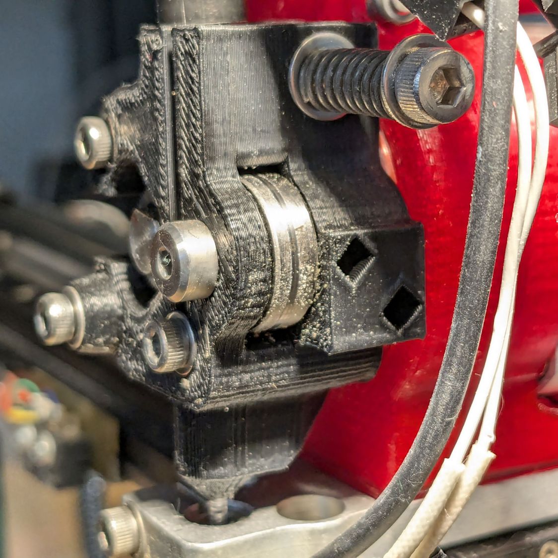
The track on the idler bearing shows the filament is neatly centered where it should be:
Makergear M2 – filament idler bearing position
I haven’t adjusted the spring pressure on the idler, but it’s probably too high for TPU. If it continues to work, I’ll continue to do nothing.
I wanted to align the magnetic base plate first, but it has a lot of magnets and steel tools just weren’t going to work:
MakerGear M2 BuildTak – FlexPlate magnets
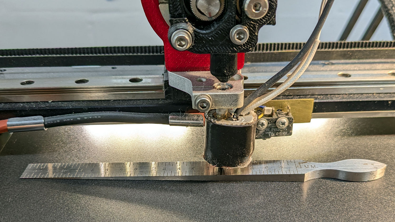
So I put the BuildTak FlexPlate on top and deployed the taper gauge, with all the magnetic fields held safely inside the steel sheet below the surface:
MakerGear M2 BuildTak – taper gauge
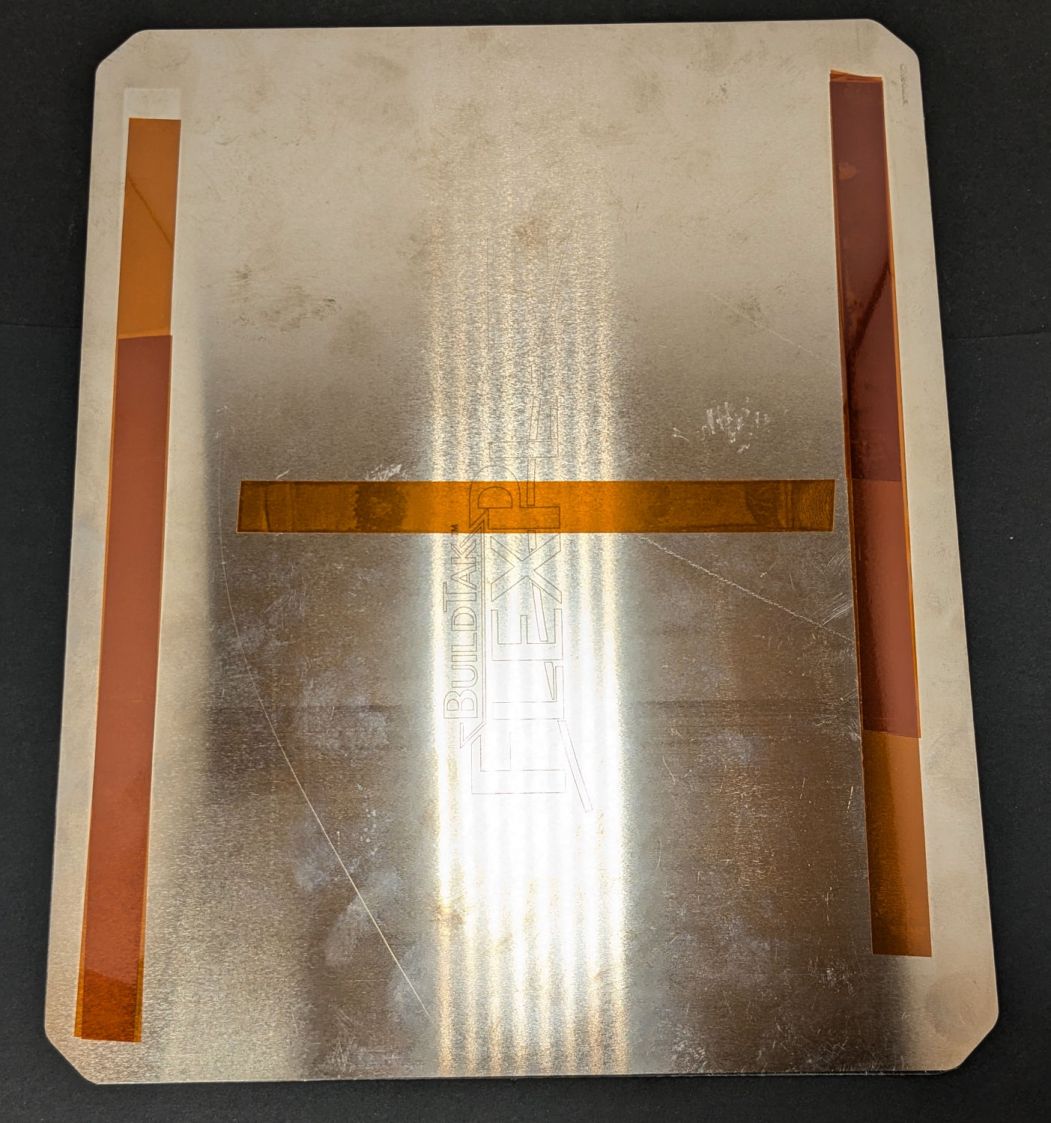
The plate turned out to be mostly flat, with two high spots at the center front and back. A few strips / layers of Kapton tape raised the lowest spots along the sides and middle enough to get the whole surface Close Enough™:
MakerGear M2 BuildTak – FlexPlate shims
That’s really thick 4 mil = 0.1 mm tape, not puny 1 mil stuff. Two layers added enough height to very slightly warp the steel plate when held down by all those magnets.
The final result was flat within ±0.05 mm across the entire plate, with those two high spots reduced to +0.2 mm.
The high spots lie outside the skirt at the front & rear of the plate, where they should be easy to avoid with most models I can imagine building in TPU. Stipulated: I have a stunted imagination.
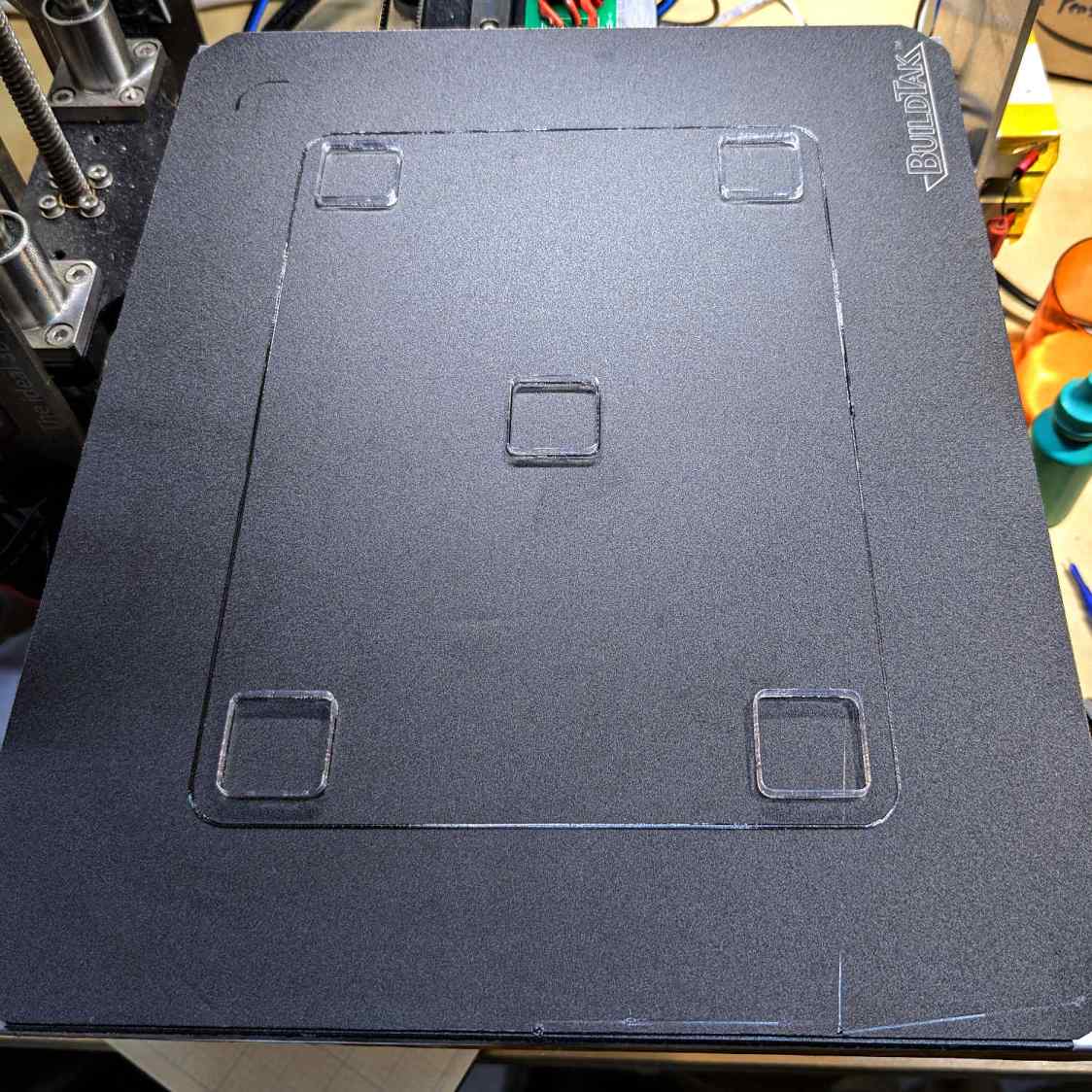
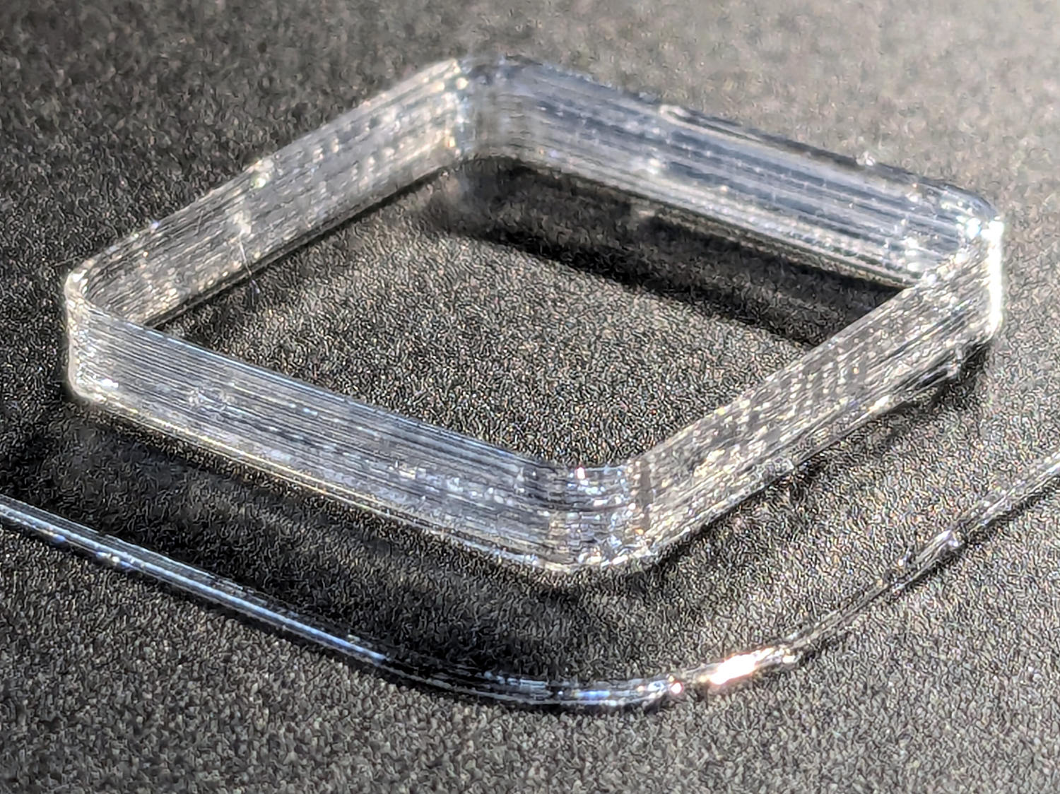
TPU boxes are bendy little things with 0.45 mm walls:
MakerGear M2 BuildTak – test square
After I got the plate flattened, even a single-thread wall of TPU sticks to BuildTak like it was glued there.
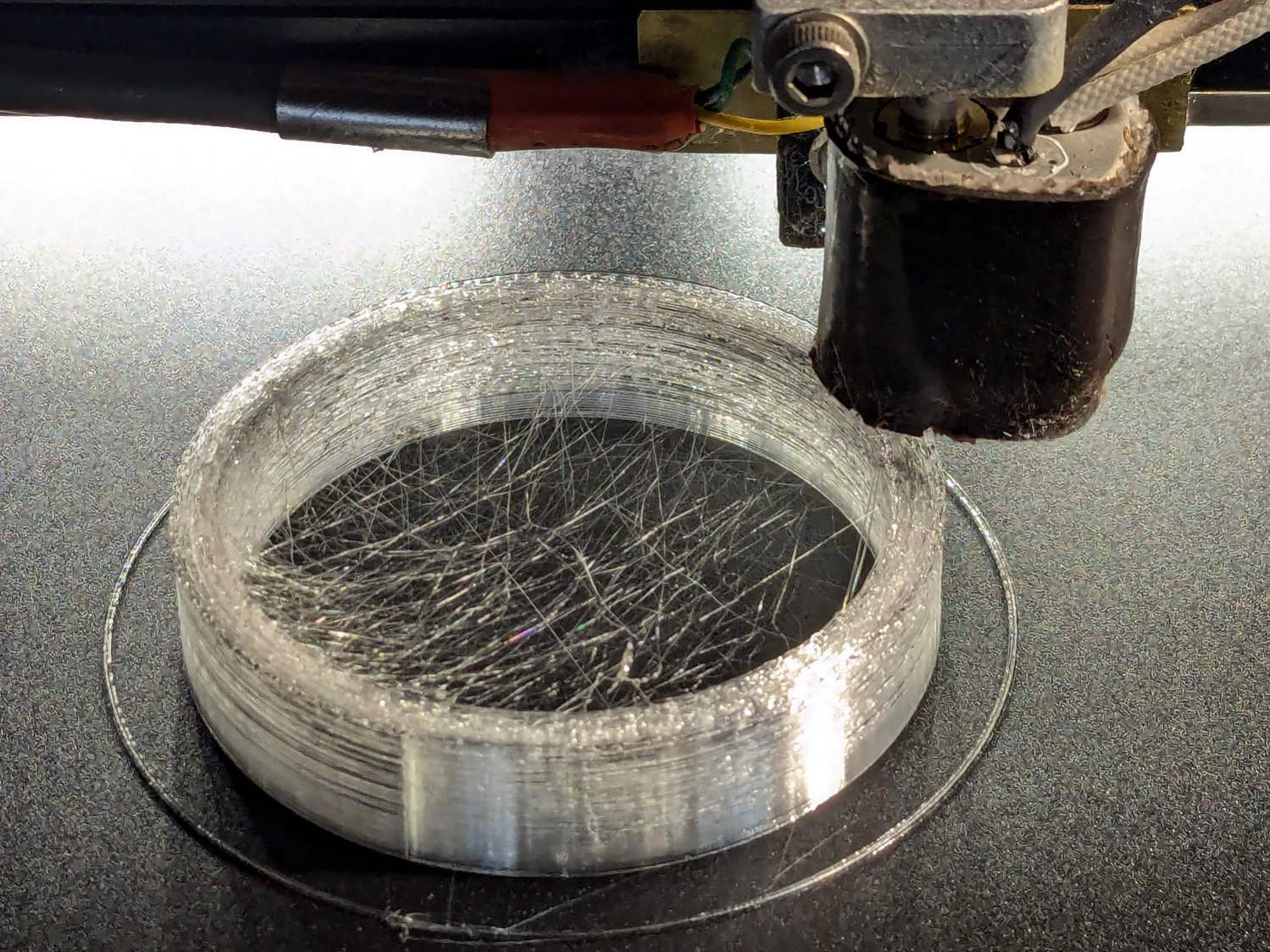
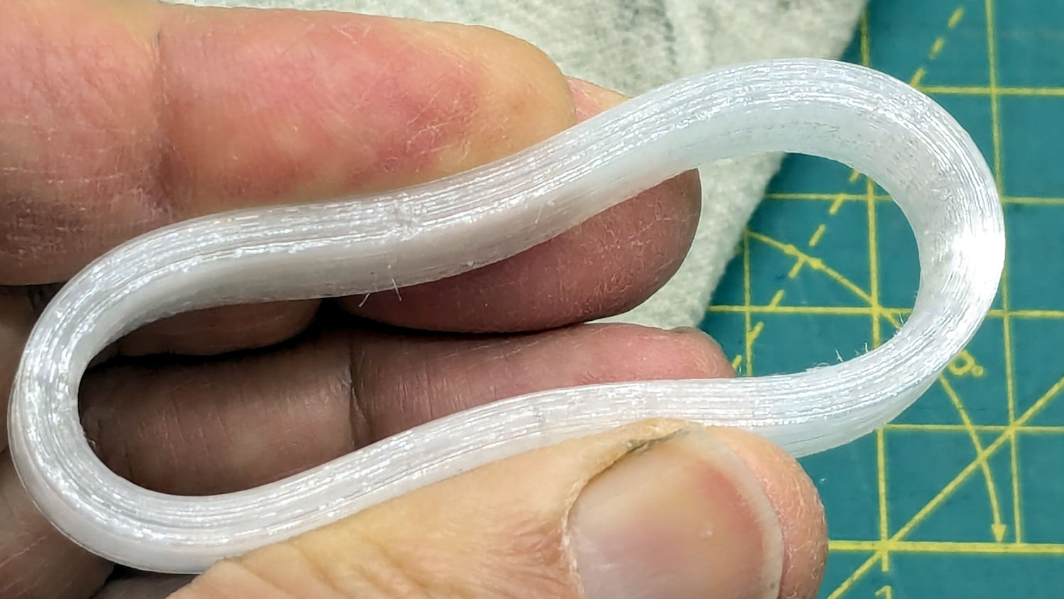
I had PrusaSlicer print them sequentially to avoid excessive back-and-forth, although combining 2 mm Retraction with Avoid crossing perimeters has eliminated much of the previous stringing:
Terracycle Chain Idler Tire – TPU stringing
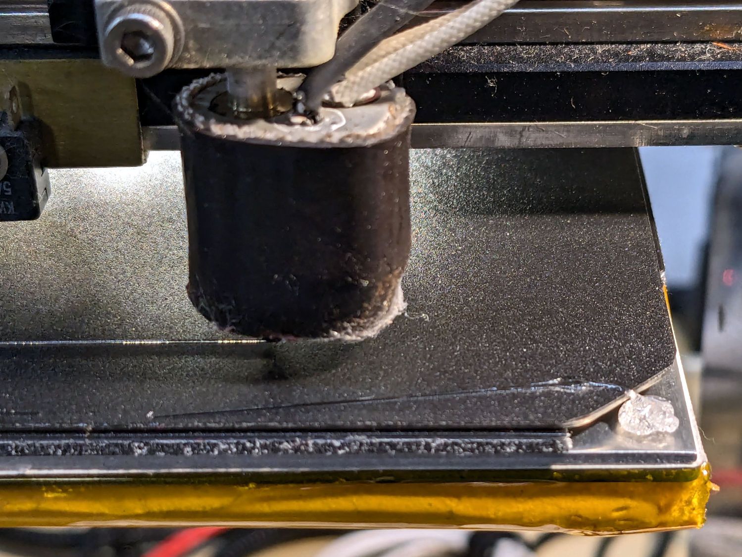
I modified the startup G-Code to purge & wipe the nozzle at the right-front corner of the plate:
MakerGear M2 BuildTak – nozzle cleaning
If I’d done that at the start, the BuildTak surface wouldn’t have a small divot melted into the center front edge where the previous G-Code paused the nozzle at the edge of the glass plate while heating. Pausing a millimeter off the diagonal seems to isolate the hot nozzle from the plastic surface.
The revised startup G-Code, with the earlier clearing motions commented out:
;-- PrusaSlicer Start G-Code for M2 starts --
; Ed Nisley KE4NZU
; Makergear V4 hot end
; Origin at platform center, set by MANUAL_X_HOME_POS compiled constants
; Z-min switch at platform, must move nozzle to X=135 to clear
; 2025-08-29 tweak priming spot to avoid scorching BuildTak surface
G90                                      ; absolute coordinates
G21                                      ; millimeters
M83                                      ; relative extrusion distance
M104 S[first_layer_temperature]          ; start extruder heating
M140 S[first_layer_bed_temperature]           ; start bed heating
M17                                      ; enable steppers
G4 P500                                  ; ... wait for power up
G92 Z0                        ; set Z to zero, wherever it might be now
G0 Z10 F1000                  ; move platform downward to clear nozzle; may crash at bottom
G28 Y                         ; home Y to clear plate, offset from compiled constant
G28 X                         ; home X, offset from M206 X, offset from compiled constant
G0 X135 Y0 F15000             ; move off platform to right side, center Y
G28 Z                         ; home Z to platform switch, offset from M206 Z measured
G0 Z2.0 F1000                 ; get air under switch
;G0 Y-126 F10000               ; set up for priming, zig around corner
;G0 X0                         ; center X
;G0 Y-125.5                    ; just over platform edge
G0 Y-121 F15000               ; set up for priming
G0 X96                        ; diagonally beyond trimmed corner of BuildTak plate
G0 Z0 F500                    ; exactly at platform
M190 S[first_layer_bed_temperature]   ; wait for bed to finish heating
M109 S[first_layer_temperature]       ; set extruder temperature and wait
G1 E25 F200                           ; prime to get pressure, generate blob on edge
;G0 Y-123 F5000          ; shear off blob
;G0 X15 F15000           ; jerk away from blob, move over surface
;G4 P500                 ; pause to attach
;G1 X45 F500             ; slowly smear snot to clear nozzle
G0 X94 Y-119 F5000      ; shear off blob
G0 X90 F15000           ; jerk away
G4 P500                 ; pause
G1 X50 Y-124 F500       ; smear snot
G1 Z1.0 F2000           ; clear bed for travel
;-- PrusaSlicer Start G-Code ends --
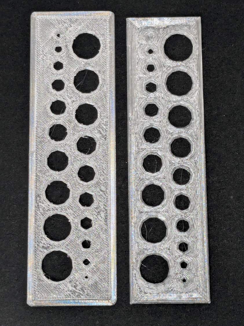
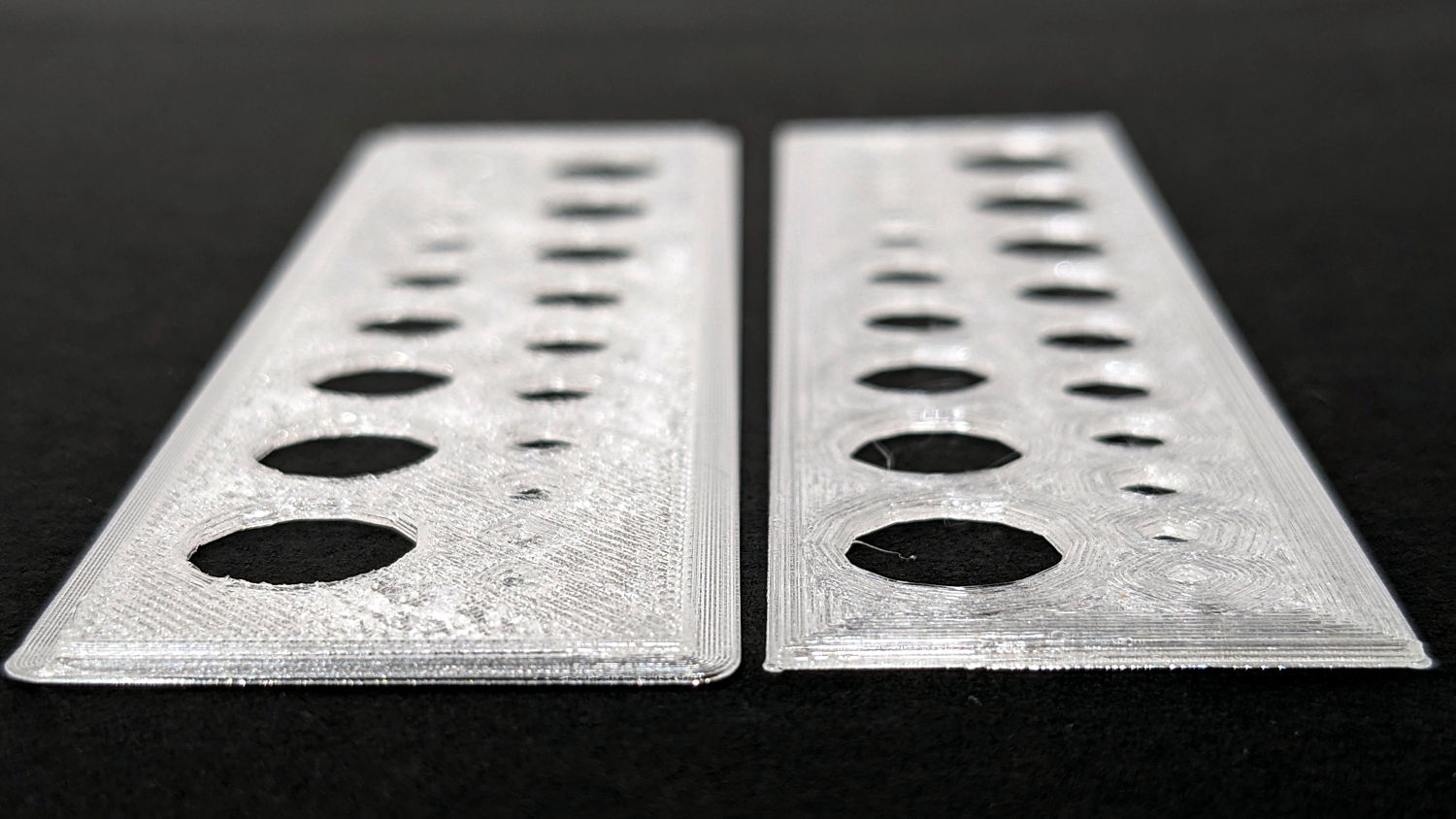
The one on the left came from the M2’s glass plate (with a brim barely improving its adhesion) and the one on the right was on BuildTak after all the fussing; I just noticed I laid them out in opposite directions.
An edge view shows the fuzzy surface on the left:
Makergear M2 BuildTak – small holes – edge
The tiniest holes in both are undersized, but AFAICT you could ram a screw through that bendy sheet without much effort.
The BuildTak sheet works well enough that I have not tried the PEI-covered FlexPlate, which I’m sure will require similar shimming to get a level surface.
And, no, I am not going to install a surface probe on the M2’s hot end.
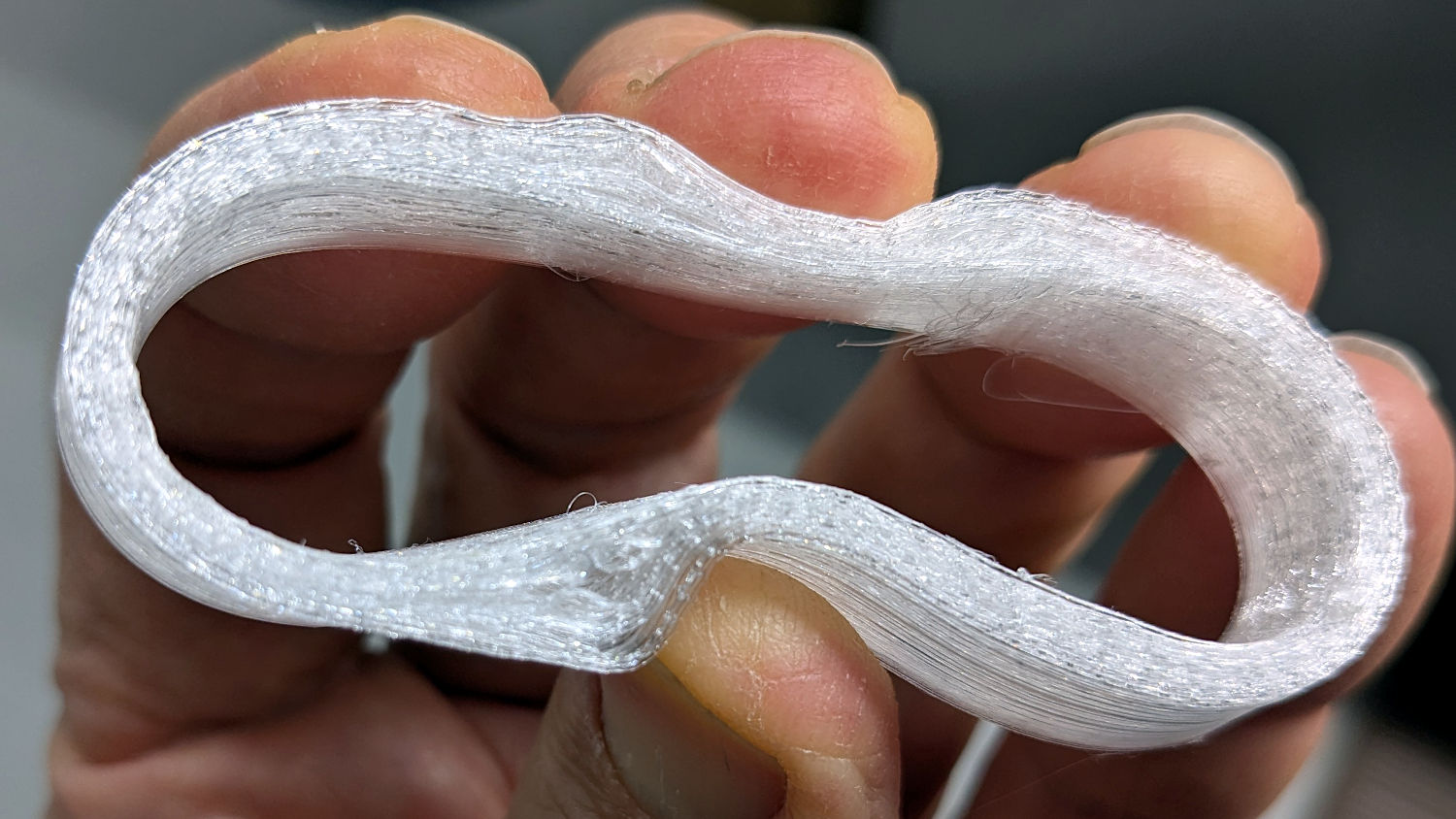
Based on someearlieritems, I’d been printing TPU at 220 °C, but 230 °C fuses the threads together:
Terracycle Chain Idler Tire – correct settings
The filament turned out to be 1.79 mm diameter, rather than the nominal 1.75 mm, and a few iterations showed a 0.95 Extrusion Multiplier worked much better.
Those were printed at 30 mm/s with 0.25 mm layer height.
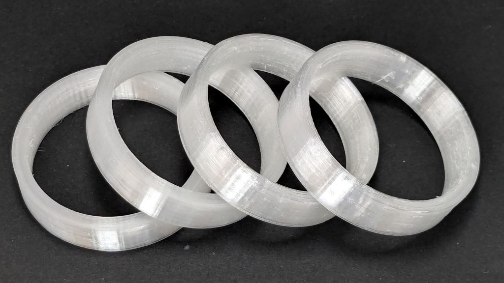
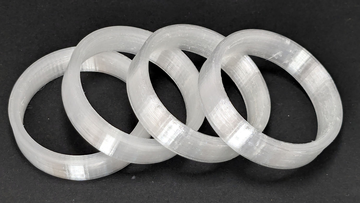
I now have a good stock of spare tires, each slightly different than all the others:
Terracycle Chain Idler Tire – spares
The first two slightly delaminated printed tires will remain in service until they show signs of falling apart, because I’d rather ride the bike than fiddle with it.
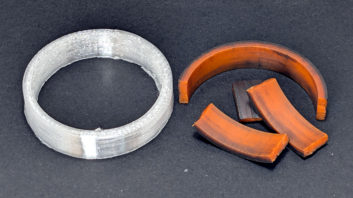
The Terracycle (now T-cycle, for reasons presumably involving the transfer of money) chain return idlers on our Tour Easy bikes developed hardening of their urethane tires:
Terracycle Idler tire – printed vs OEM
Urethane shouldn’t crack like that, but after more than fifteen years, stuff wears out.
The white ring is 95A TPU printed on the Makergear M2, which is definitely more flexy than the original tire, but has the redeeming feature of being both Good Enough and trivially easy to model:
include <BOSL2/std.scad>

NumSides = 4*3*2*4;
$fn=NumSides;

Thick = 3.5;
ID = 46.4;
OD = ID + 2*Thick;
Length = 11.2;

tube(Length,id=ID,od=OD,anchor=BOTTOM);
It printed with 5 mm brims on both the ID and OD, because TPU has the barest adhesion to the M2’s glass plate + hair glue. There’s a long-unopened box now on the bench with a BuildTak PEI surface (thank you: you know who you are!) that should improve the situation.
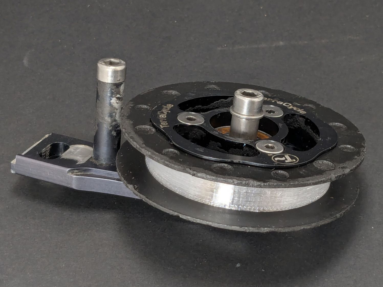
In any event, the tires fit well:
Terracycle Idler tire – installed
The layer-to-layer adhesion isn’t as good as I think it should be, so I’ll likely use those tires as testcases for tweaking the new build plate & settings.
Mary found the wrench I made five years ago in the bottom of her tool bucket:
Hose Valve Knob – five years later
Having moved away from the garden with all the valves that wrench turned, it can now go into the 3D Printed Sample Box for use in the unlikely event I ever give another talk on the subject.
I’d design it differently these days, what with BOSL2 in my sails, but it got the job done.
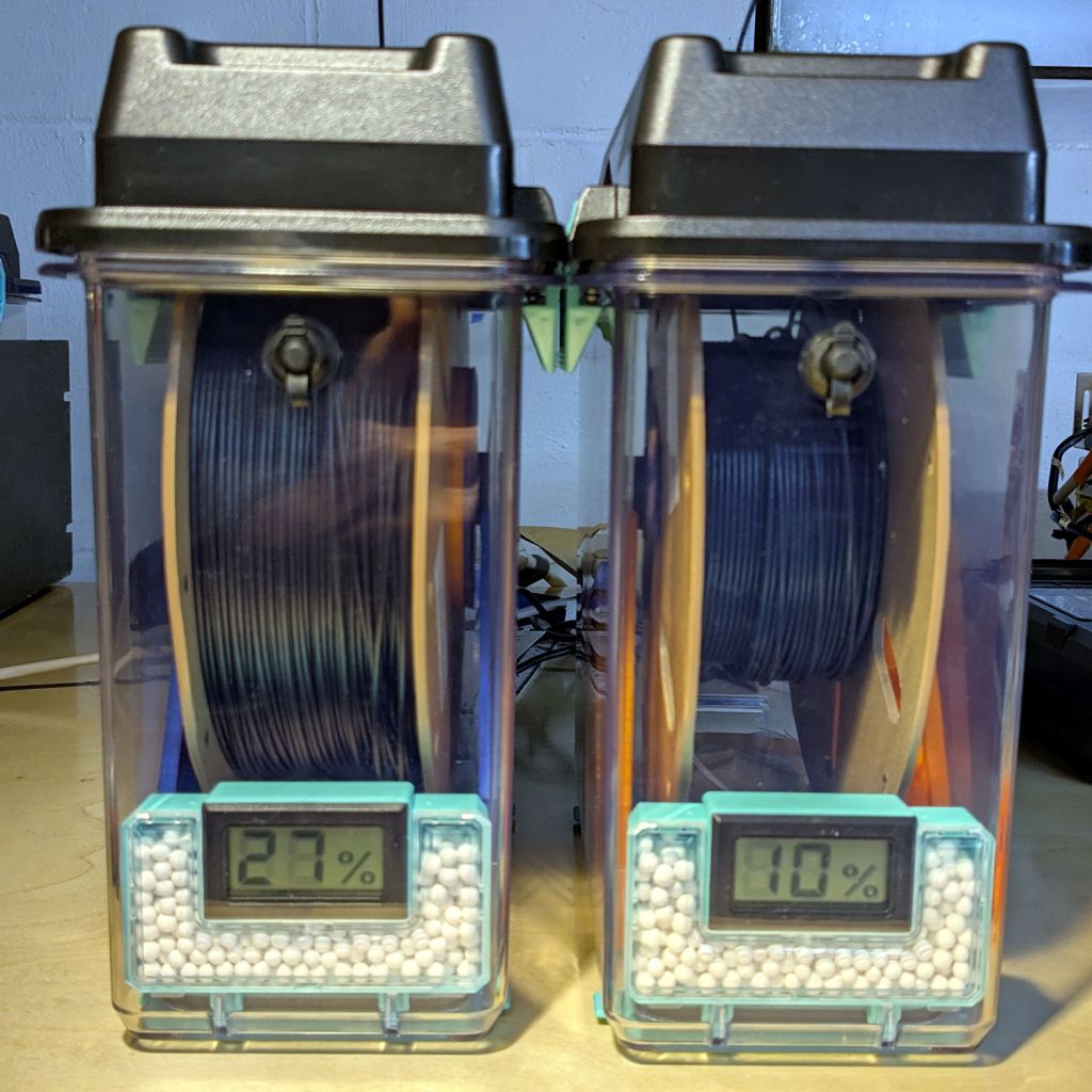
The Basement Shop has 50±5% relative humidity, with the top held down by a hulking dehumidifier (plus a box fan stirring the air) and the bottom supported by being a basement. As a result, the 3D printer filament stabilized at about 50% RH, which seemed to work well enough for PETG.
That’s activated alumina desiccant, mostly because it’s reputed to have more capacity and a lower ultimate humidity than silica gel, but it likely doesn’t make much difference.
In addition to 25 g of desiccant in the PolyDryer meter case, I dropped five teabags holding 10 g each in the bottom of the box for more capacity. I measure the desiccant by putting 75.0 g into a cup, putting 25.0 g in the PolyDryer meter box (aided by a Polydryer Desiccant Funnel), 10.0 g into four teabags, and whatever’s left into the fifth teabag, thus eliminating rounding errors in the smaller quantities.
The stabilized humidity inside the boxes seems to depend on the amount of filament on the spool:
Nearly full → 25% to 30% RH
Half full → 20%-ish RH
Nearly empty → 10% to 15% RH
I think the humidity level comes from the filament outgassing water vapor through its (limited) surface area on the outer layer around the spool. The difference between that rate and the desiccant’s ability to remove water vapor from the (unmoving) air in the box sets the stable humidity: more surface area → more water vapor → higher humidity.
After the filament eventually dries out, the humidity should decrease, but diffusion is a slow process. More likely, the humidity will remain stable as the printer pulls filament from the outer layer and exposes the somewhat wetter plastic within.
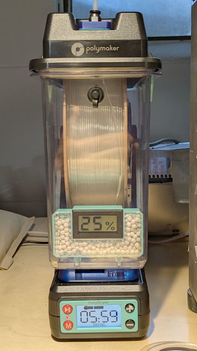
The heater and fan inside the PolyDryer base unit circulates hot air through the box around the spool, but depends on the desiccant to remove water vapor. Running the base unit for 6 or 12 hours makes little difference in the stabilized humidity, so I think the desiccant is doing the best it can as the filament outgasses more water vapor.
Using Air Exchanger vents seems to make no difference, likely because the desiccant must then pull more water vapor out of the incoming 50% RH basement air. A psychrometric chart says 50% RH air at 60 °F becomes 10% RH air at 120 °F, but moisture in the filament wrapped around the spool can’t escape any faster.
So, for example, a full spool of TPU starting at 25% RH:
PolyDryer humidity – TPU start
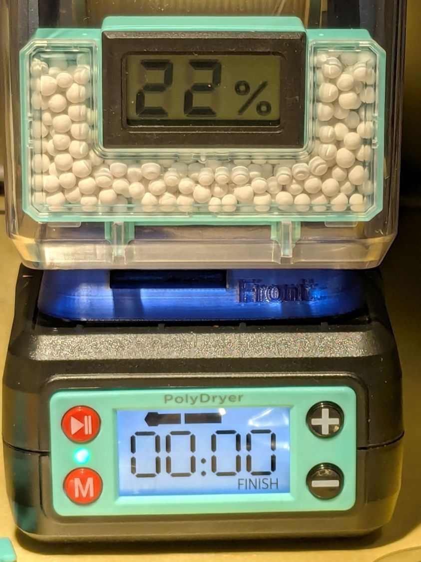
Six hours of drying pulls it down to 22%:
PolyDryer humidity – TPU finish
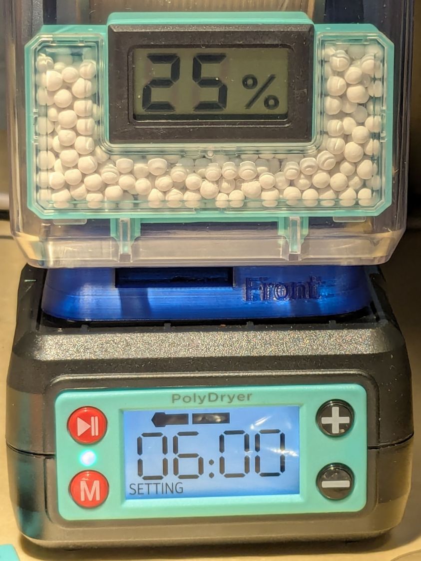
After sitting overnight it’s back at 25%:
PolyDryer humidity – TPU after 14 hr
Admittedly, that was with the vents in place, but the closed box started at 25% RH after sitting around for a week or so following a similar drying cycle.
The desiccant had absorbed 4 g of water since I put it in, so it hasn’t been entirely idle.
Which suggests 75 g of activated alumina desiccant is workin’ hard and doin’ swell in there, with the filament acting as an essentially infinite reservoir of water vapor.
I haven’t noticed any particular difference in PETG print quality and the TPU hasn’t gotten enough mileage to notice much trouble, but reducing the MMU3 buffer clutter was totally worth the effort.
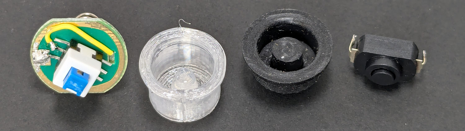
The switch on the Anker LC-40 flashlight serving as a running light on my Tour Easy became slightly intermittent before I replaced it with a 1 W amber LED, but it was still good enough to become the troubleshooting flashlight in the tray next to the Prusa Mk 4 printer. Eventually, of course, it failed completely and Something Had To Be Done.
Although I knew an exact replacement switch had to be available from the usual sources, I could not come up with a set of keywords capable of pulling them out of the chaff.
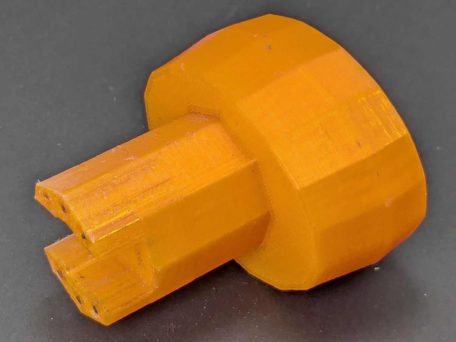
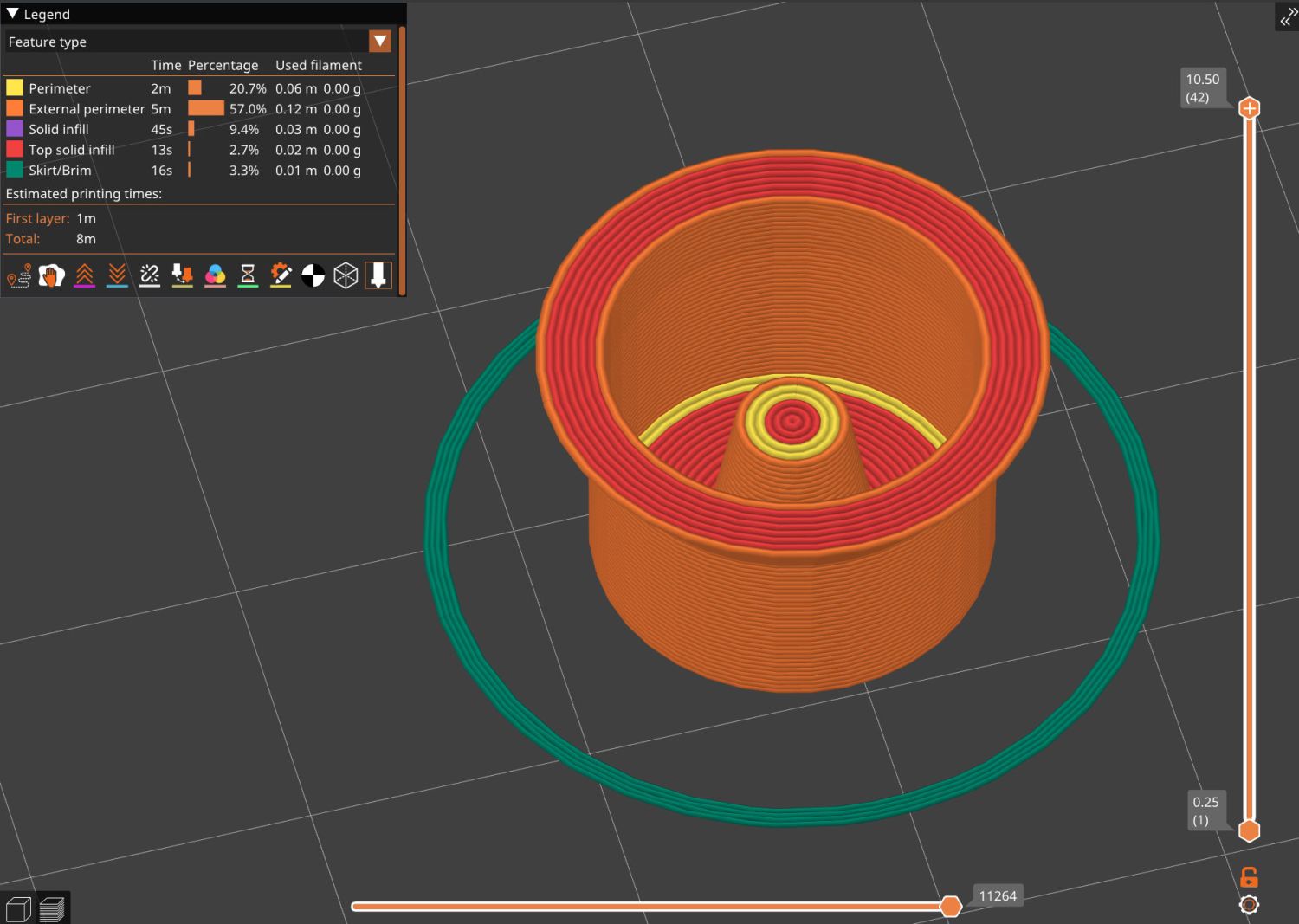
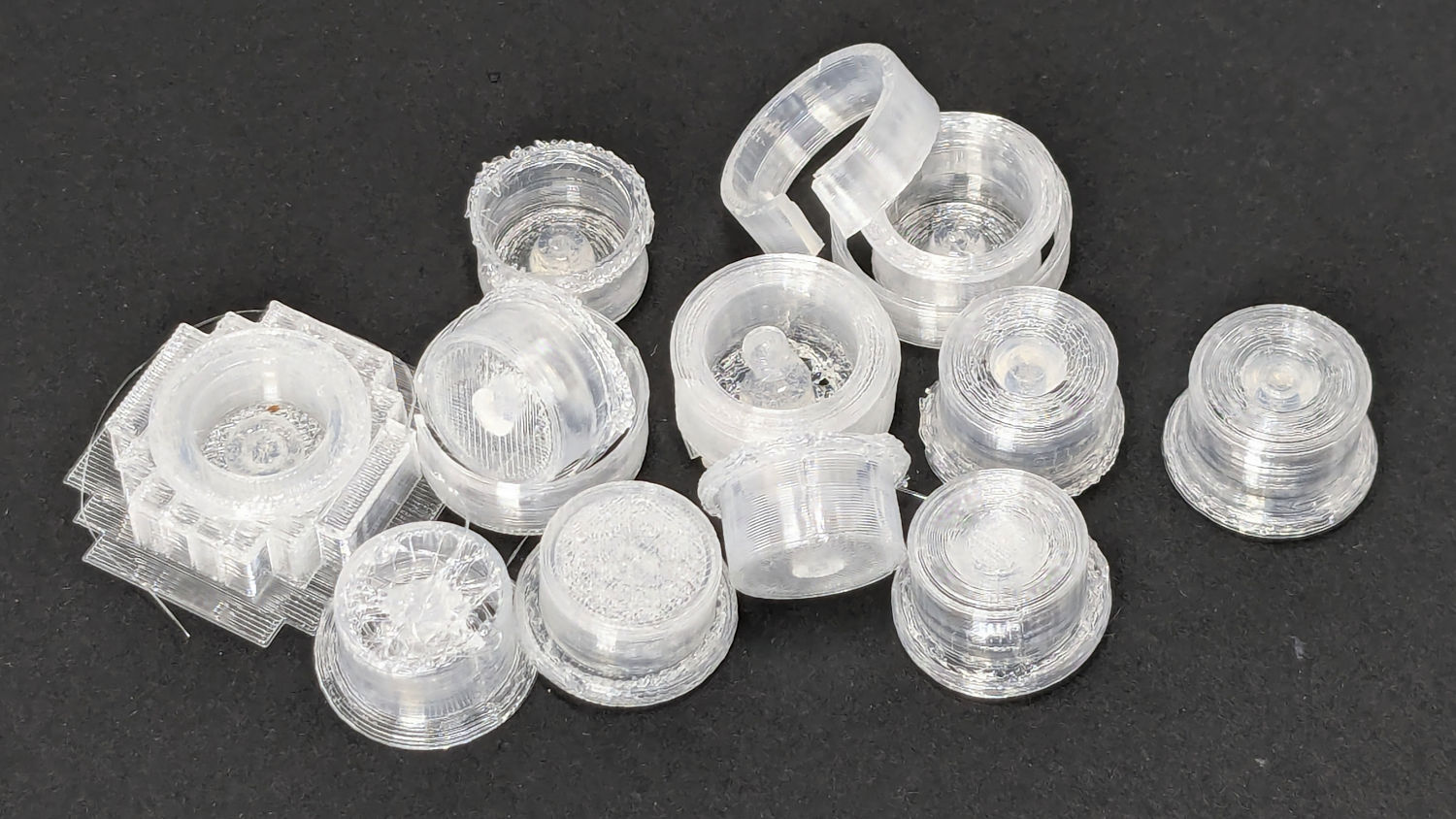
Which turned into a multi-dimensional search over cap geometry, TPU extrusion speeds & feeds, and various impossible-to-directly-measure sizes:
Anker LC-40 Flashlight – TPU cap iterations
The squarish block over on the left is PrusaSlicer’s version of a support structure wrapped around the first cap version; if human lives depended on it, I could surely extract the cap, but it would take a while.
The remaining debris samples occured while discovering:
An extruder temperature of 230 °C, not 250 °C, works well
A conical shape of the lip around the open end to eliminate the support structure
TPU doesn’t bridge well, so the closed end must be down
Length of the central pillar to barely touch the switch stem when released
Cap length and wall thickness so the TPU shell can collapse enough to actuate and release the switch stem
Because I expected this would be an easy job, I used snap ring pliers to unscrew and rescrew the threaded retaining ring holding the switch PCB in place. Because the pliers didn’t have a stable grip on the ring, the threads eventually became just a bit goobered.
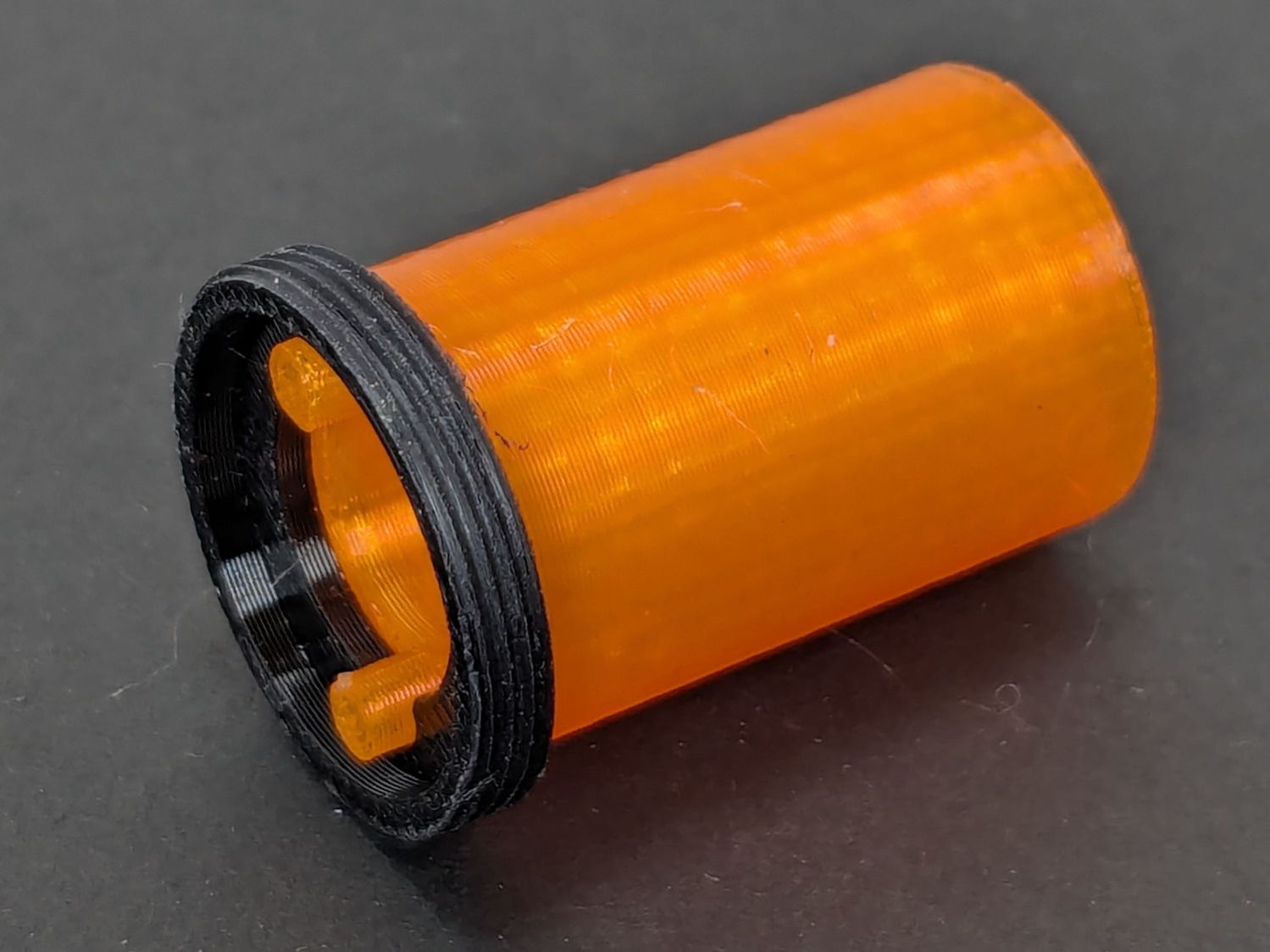
This was not a problem, because I have a(nother) 3D printer:
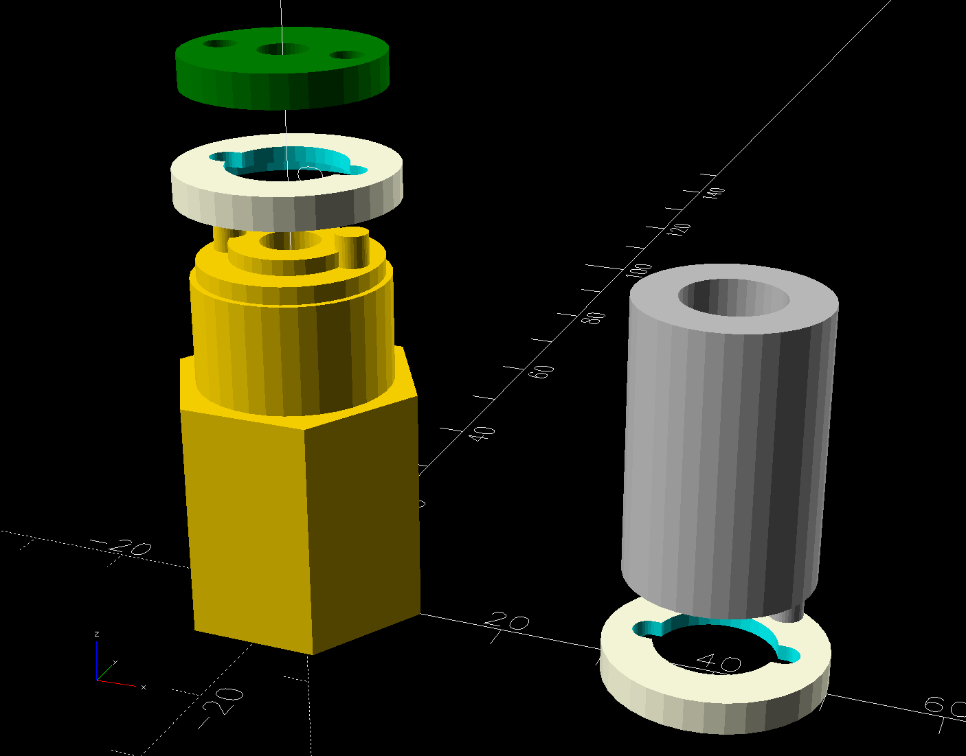
Anker LC-40 Flashlight Retainer – show view
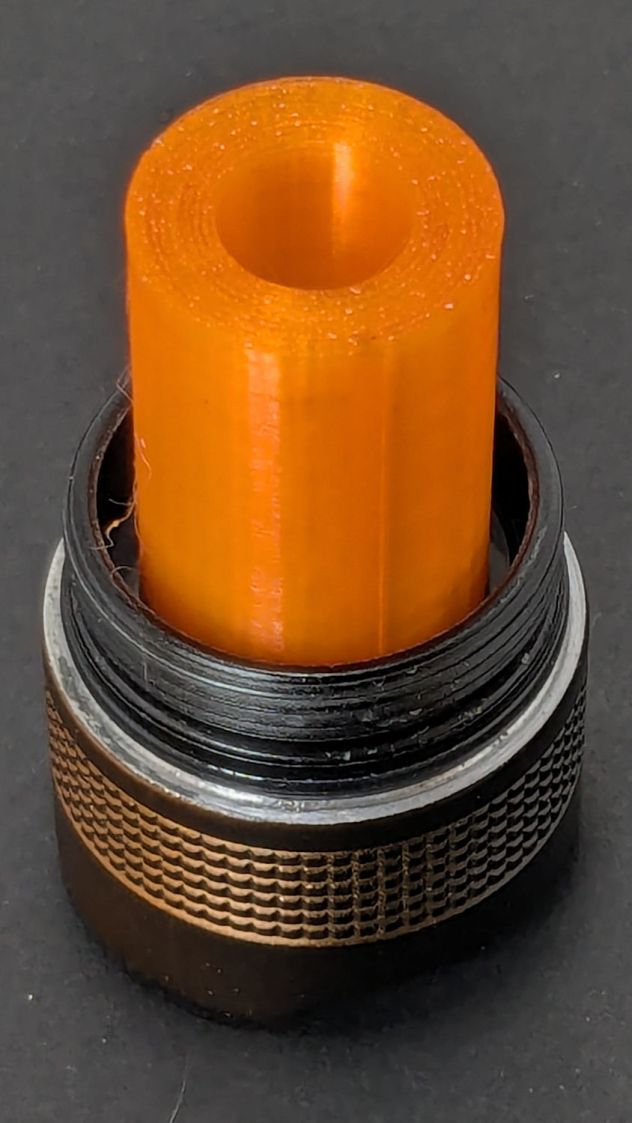
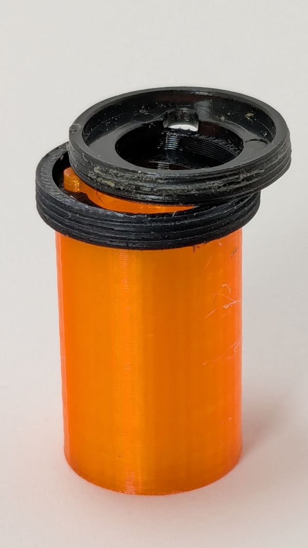
The gray thing on the right is a simple pin wrench fitting both the original and the replacement retaining rings, so I can orient the rings properly while unscrewing & rescrewing:
Anker LC-40 Flashlight – pin wrench in place
The threads have a 0.75 mm pitch and, while it’s possible to print screw threads, even a tedious 0.1 mm layer height would define each turn of the thread with only 7-½ layers.
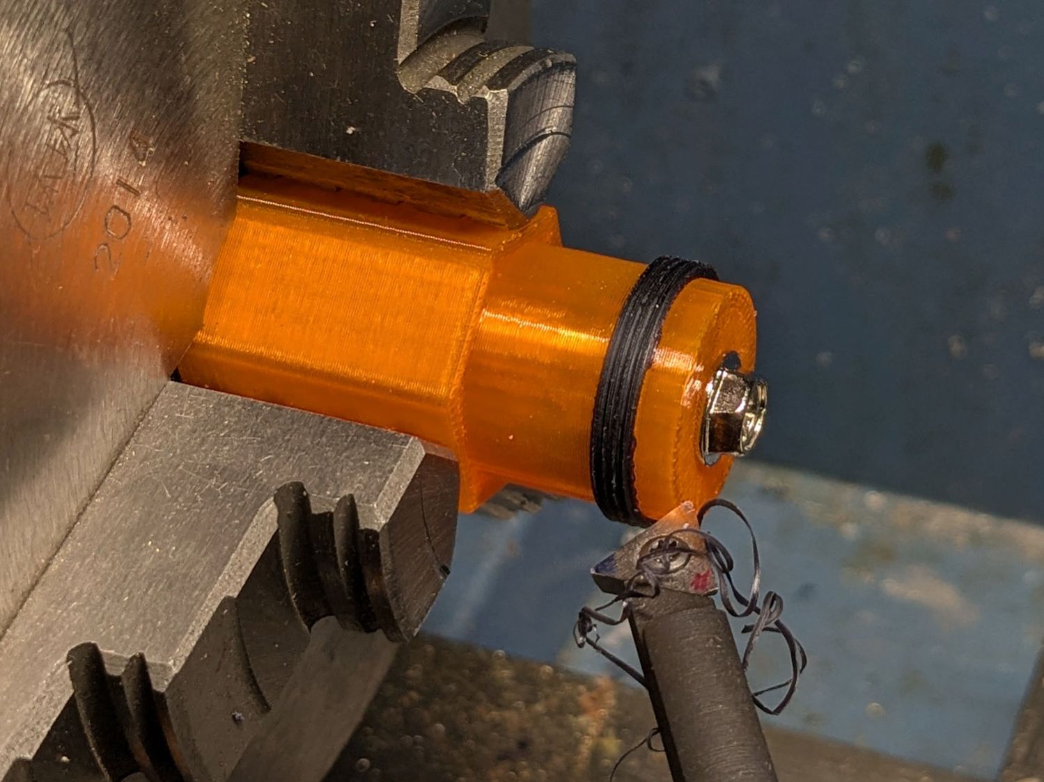
This was not a problem, because I have a mini-lathe:
Anker LC-40 Flashlight – thread cutting
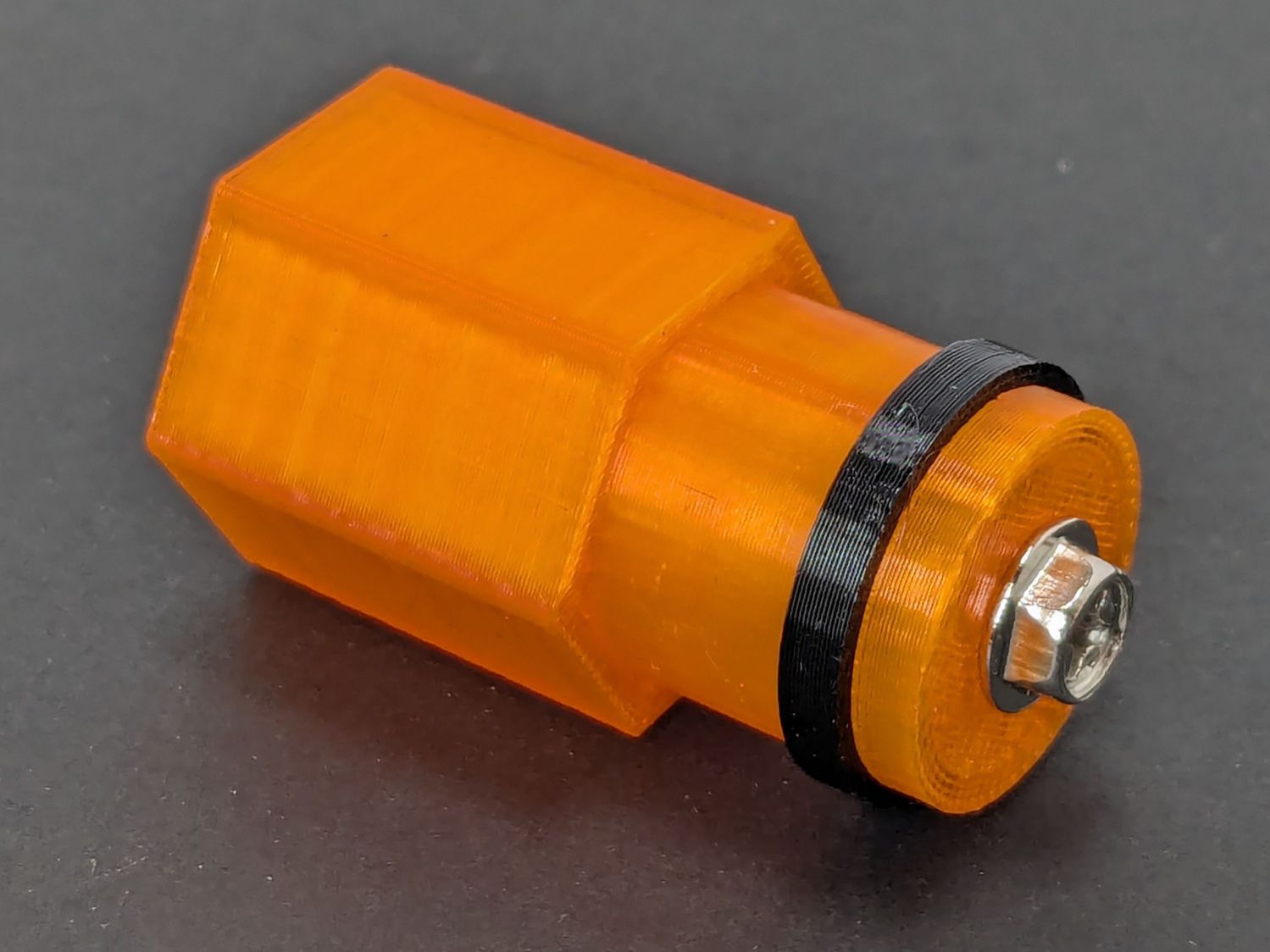
The yellow & green things on the left of those solid models are the fixture holding a retaining ring for threading and the washer applying pressure to keep the ring in place:
Anker LC-40 Flashlight – lathe fixture – detail
The alert reader will note that washer lacks holes for the alignment pins I added after seeing the washer sit not quite concentric on the fixture. I could call it continuous product improvement, although I doubt I’ll print another one.
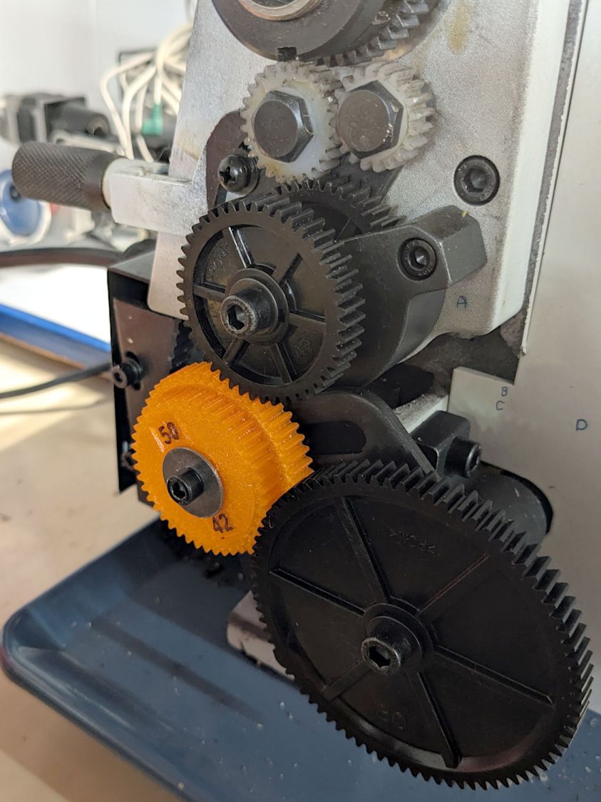
Setting up the lathe involved finding the proper set of change gears, including the vital 42-50 stacked gear I made a while ago to print metric threads on a hard-inch lathe:
Anker LC-40 Flashlight – lathe change gear train
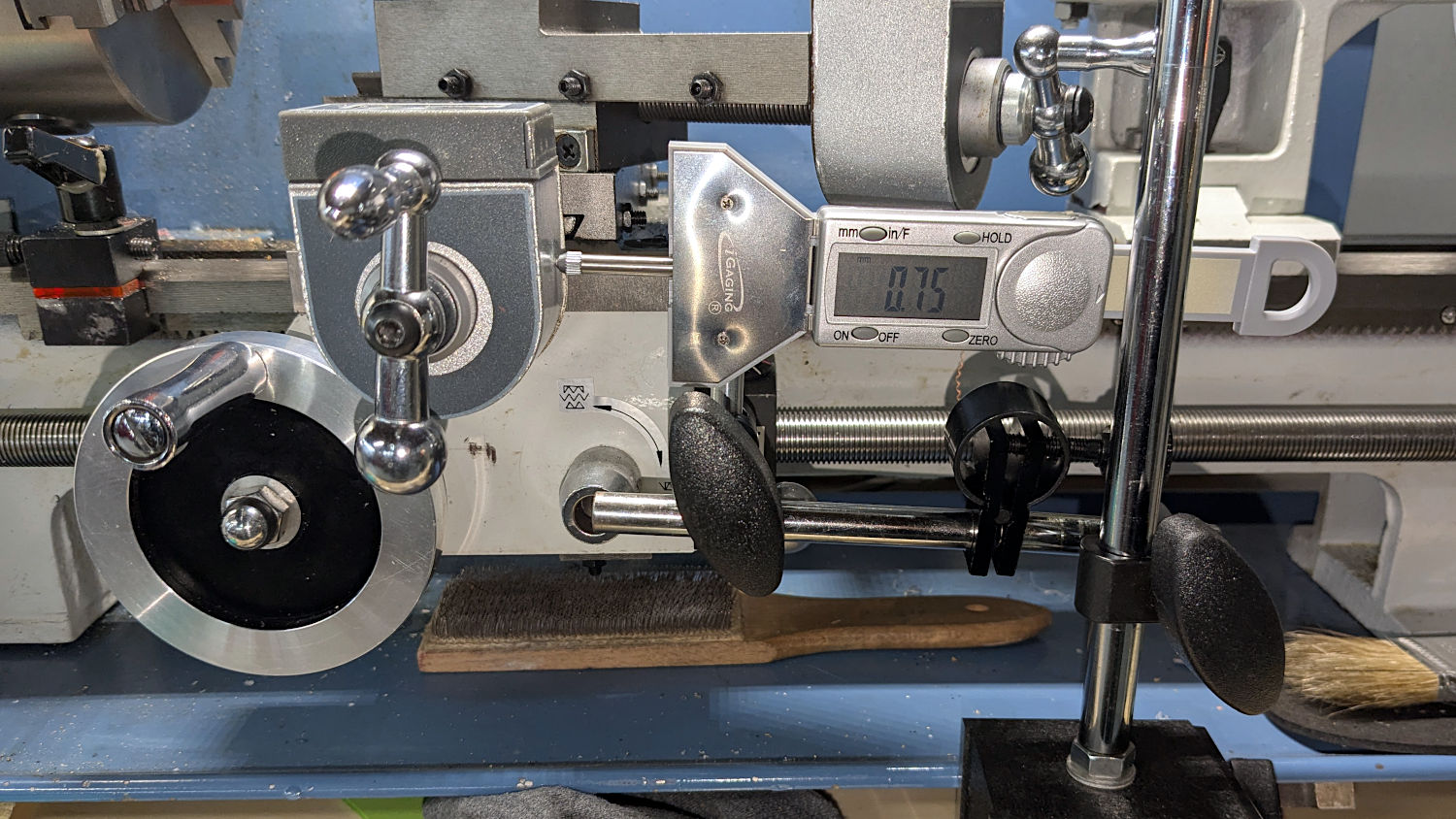
Although you’re supposed to measure the thread spacing on a skim pass, I find it’s easier to just measure the carriage movement for one spindle rotation:
Anker LC-40 Flashlight – lathe gear check
A few passes produced a fine retaining ring:
Anker LC-40 Flashlight – OEM vs lathe-cut threads
Sporting much nicer looking threads than the goobered original:
Anker LC-40 Flashlight – OEM vs lathe-cut threads
The original switch had a stabilizing ring around the body to prevent it from wobbling under the original rubber cap.
This was not a problem, because I have a laser cutter:
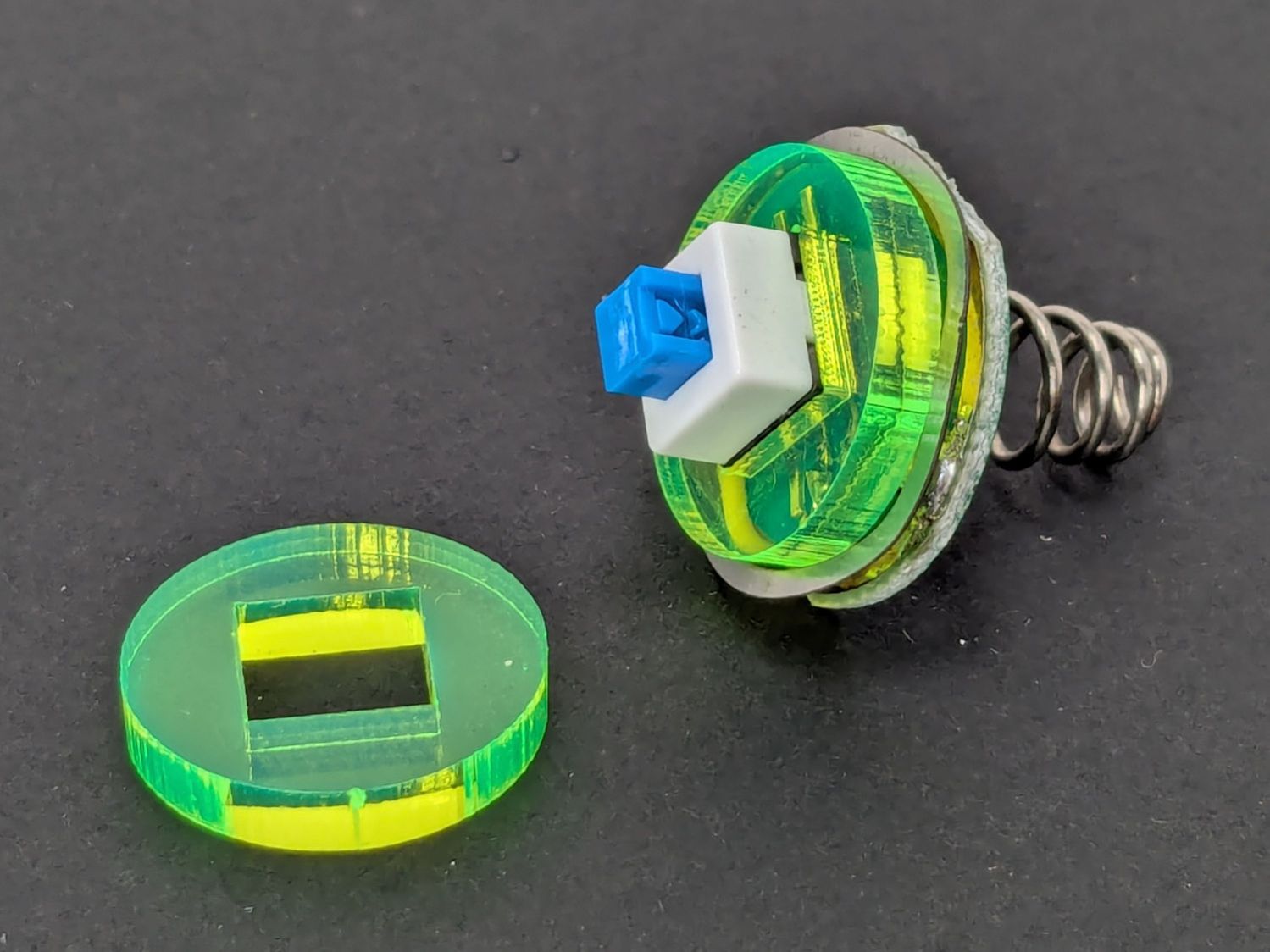
Anker LC-40 Flashlight – new switch in stabilizer
Those came from a scrap of fluorescent acrylic.
The wave washer behind the acrylic stabilizer improves the contact between the PCB trace around the rim and the flashlight tailcap, with the current passing through the body to the “light engine” up front. The retaining ring provides enough pressure to compress the wave washer, which is why it’s so easily goobered without a close-fitting pin wrench.
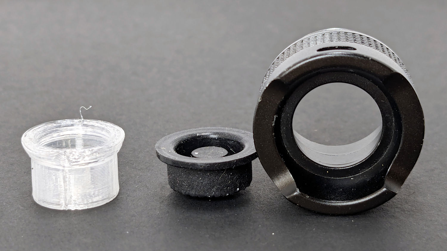
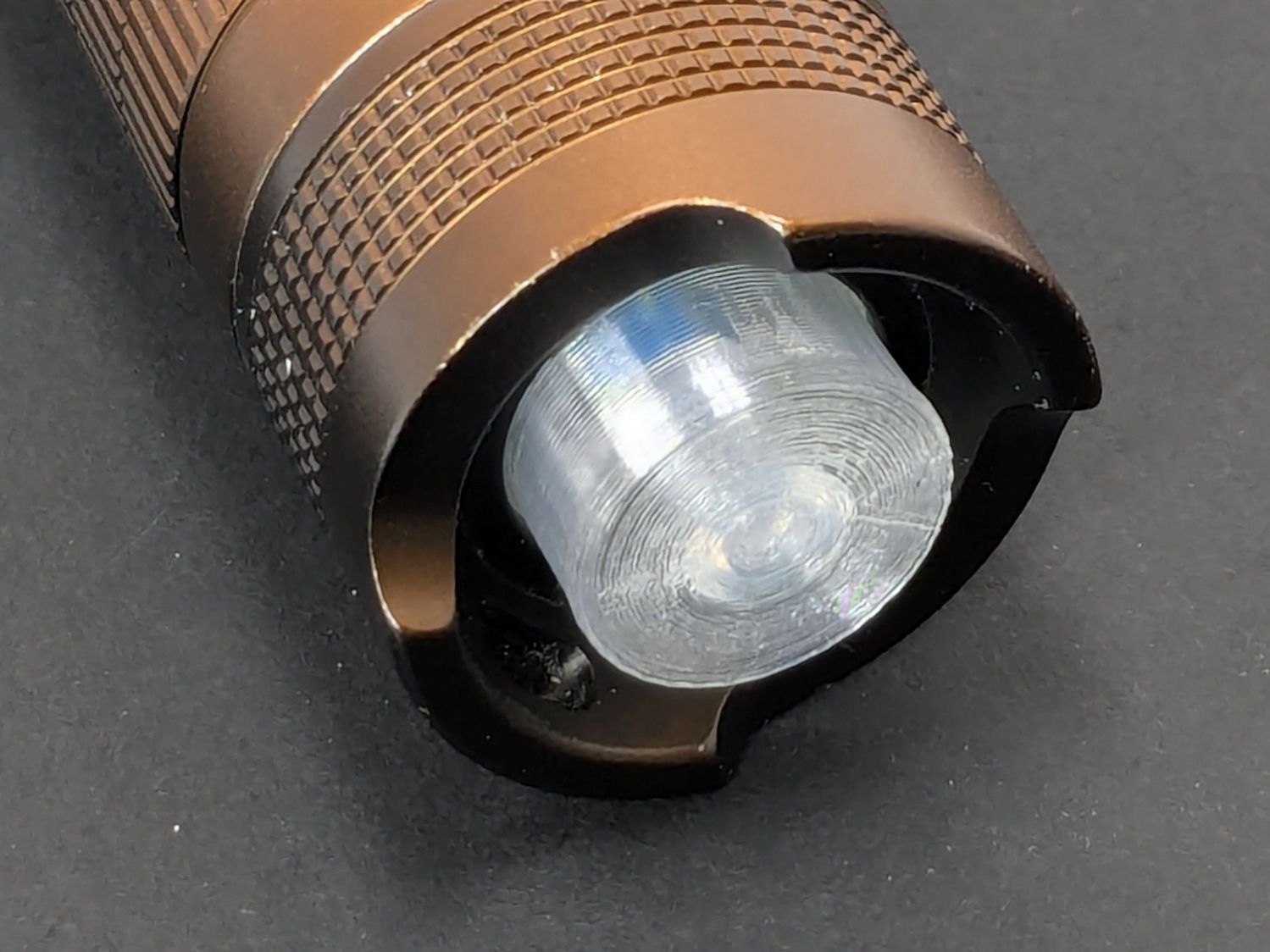
With everything assembled in reverse order, the flashlight worked pretty much as it did back when it was new:
Anker LC-40 Flashlight – TPU cap installed
However, after describing this during a recent SquidWrench meeting, I discovered that adding “latching” to my keywords surfaced a bodacious assortment of flashlight switches, so (a few days later) I removed the not-quite-right switch and replaced it with an identical twin of the OEM switch requiring just a little lead forming to fit the PCB.
Even better, using the 3D printed pin wrench to screw the original retaining ring into the flashlight’s aluminum threads a few times re-formed (unrelated to recent electrolytic capacitor reforming) its goobered threads well enough to fit and work perfectly again.
So I have:
… reassembled the flashlight with more-or-less original components
… a repair tool kit ready when another LC-40 fails
… re-learned the lesson that any time spent making a fixture or a special tool is not deducted from one’s allotment
This file contains hidden or bidirectional Unicode text that may be interpreted or compiled differently than what appears below. To review, open the file in an editor that reveals hidden Unicode characters.
Learn more about bidirectional Unicode characters