Ed Nisley's Blog: Shop notes, electronics, firmware, machinery, 3D printing, laser cuttery, and curiosities. Contents: 100% human thinking, 0% AI slop.
A backlash test found on the LightBurn forum puts the machine through a series of difficult maneuvers:
Backlash test
That’s burned on the back of a paperboard box at 400 mm/s @ 15%/10% power, which is slightly too intense for the smaller patterns.
The key point is that the machine has no detectable trace of backlash, with all the opposing lines matching up and equal spacing regardless of the approach direction.
The larger targets on the right let the machine reach a speed closer to the nominal 400 mm/s around the arc, so the cut along the tape tab after the right-angle turn comes out a bit wobbly; the smaller targets are fine. The red lines are just under 0.5 mm wide and the wobble is on the same order, so it’s pretty close to being OK.
Being a guy of a certain age with a diagnosis of Low Bone Density, I must increase my calcium intake. Rather than add a few hundred calories a day of calcium-rich food that my waistline does not need, I’ll see what adding 600 mg of calcium citrate can do.
Being a guy of a certain type, I prefer to fill my own capsules, which of course involves Quality Shop Time:
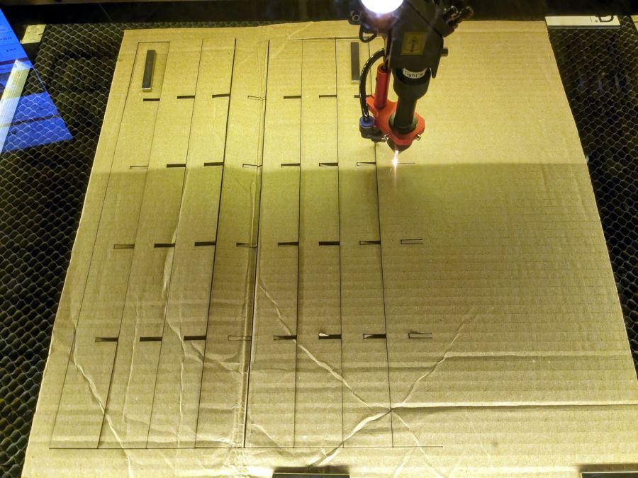
Gelatin 000 Capsule Fill Plate – cutting
Quite some years ago, for reasons not relevant here, I acquired several of what were called “manual capsule filling machines” from the usual online sources. During the ensuing years, such devices have fallen under the purview of the DEA and vanished from the import market, leaving (AFAICT) one USA-ian supplier.
The key difference between “machines” for different capsule sizes is the plate holding the capsule bodies:
Gelatin 000 Capsule Fill Plate – installed
A complete machine includes three other capsule-size-related parts:
A plate holding the caps
A plate with conical holes used to shake caps & bodies into their respective plates
A guide plate helping mate caps with bodies
In normal use, you put the “shake plate” on the body or cap plate, dump a pile into it, and shake until most of the caps / bodies fall into the holes. Then you manually insert the rest, invert any that fell in backwards, and generally mess around until they’re all properly oriented in their sockets. After filling the capsules, you put the cap + guide plates atop the bodies, press down firmly, and (ideally) produce 100 filled and sealed capsules.
It turns out Size 000 capsules are sufficiently chonky that I have no trouble capping the bodies by hand without those other parts, so making just the body plate seemed Good Enough™. The story might be different for Size 1 capsules.
The external dimensions and screw holes match the original plate, so this one fits the same base:
Gelatin 000 capsule plate – LB layout
Make one plate and four spacing clips from 6 (-ish) mm acrylic.
If you can think of anything to do with 100 3/8 inch cylinders of 1/4 inch acrylic, clue me in.
Size 000 bodies are close enough to 3/8 inch that I cleaned up the holes with a step drill for a nicer fit. Perhaps making the plate from 3 mm acrylic would produce better results.
Four springs around the screws in the corners support the plate to allow pressing the caps in place. I adjusted the screws to put the top of the plate at exactly the height of the bodies above the blue base place, producing a smooth surface for scraping suspicious white powder into the bodies:
Gelatin 000 Capsule Fill Plate – filled
Iterate filling and tamping until the capsule contents are firm-but-not-overstuffed, then press the plate downward and secure it with the spacer clips:
Gelatin 000 Capsule Fill Plate – capped
The clips hold the plate at the proper distance to let the caps slip over the bodies and lock in place. This is tedious, but much faster than doing the entire process on individual capsules one-by-one.
With the caps locked in place, flip the whole thing above a bowl, remove the clips, press the plate against the base, and 100 finished capsules shower into the bowl.
You could build a complete filler without having the blue base plate & springs, but I’ll leave that project to your imagination.
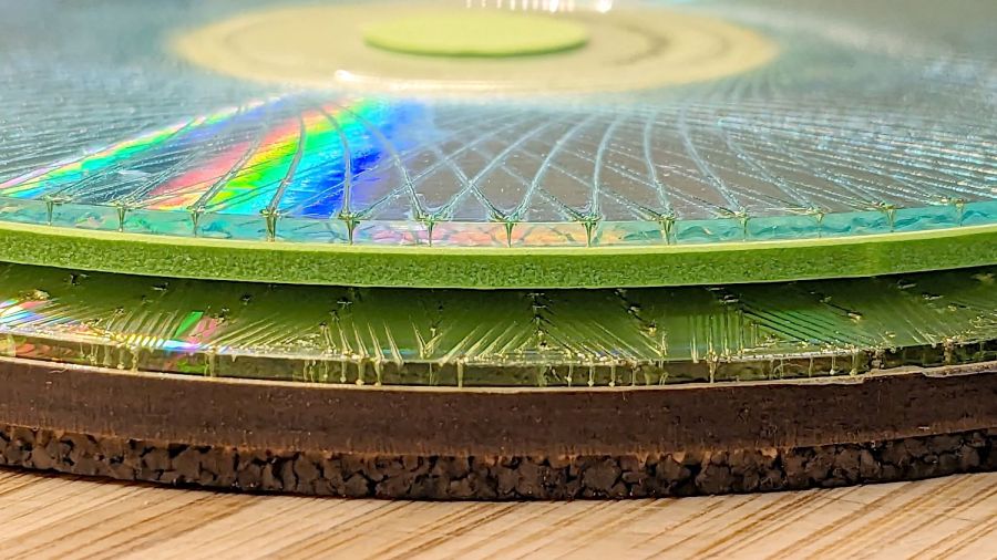
Having stuck many cork bottoms to many coasters and aligning nearly all of them pretty close, I finally made a fixture to get it right from now on:
Coaster cork fixture – test fit
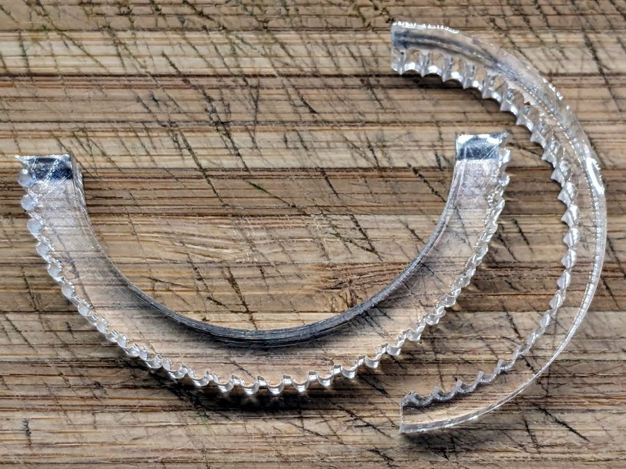
A plywood disk anchors four arcs cut from a remnant of acrylic mirror left over from the card-suit coasters, using strips of adhesive sheet cut 1 mm smaller than the arcs:
Coaster cork fixture – adhesive sheets
Stick an arc in place, lay the cork inside the arc, and stick the rest of the arcs around the cork:
Coaster cork fixture – cork fit
Squish the arcs in place overnight with Too Many Clamps™:
Coaster cork fixture – clamping
In use, peel the paper off the cork, lay it in place, ease the coaster atop it, press firmly, remove the perfectly aligned coaster, then put a stack of them in the overnight clamp to solidify the PSA bond.
Having established that scribbling Sharpies on laser-cut acrylic is a Bad Idea™ due to stress cracking, I made some acrylic mirror coasters with rattlecan spraypaint on the back:
Back-painted mirror coasters
The colors, which look much more obvious in person, are gray, black, and blue. There should be a diamond to round out the playing card theme, but only three fit neatly on the remaining slab of mirror.
A slide show giving a closer look:
Back-painted mirror coaster – gray detail
Back-painted mirror coaster – black detail
Back-painted mirror coaster – blue detail
In person, all of the gritty edges and imperfections vanish, because they’re all well below eyeballometric resolution: you can see them, but only if you look hard.
Those are at 500 mm/s and 15% PWM, which is too fast for fine details due to the HV power supply’s bandwidth limitations. However, the tube doesn’t fire reliably below about 10% and tends to sprinkle speckles over the surface, so there’s not much leeway to slow down.
That’s after an inadvertent drop edgewise onto the concrete patio.
Stipulated: given what I’ve already done to / for the thing, the usual warranties do not apply.
The frame around the NP-BX1 lithium batteries held the glass fragments together surprisingly well:
Kitchen scale – shattered glass – detail
Of course, harvesting the good stuff resulted in a pile of fragments, but the carcass cleaned up nicely and, after grafting a temporary top made from scrap acrylic it still worked:
Kitchen scale – temporary surface
I expected to just cut a slab of 6 mm acrylic to match the original 5 mm glass, but for reasons probably related to dielectric constants, the touch controls do not work through that much acrylic. In fact, they don’t work through anything other than the 1.5 mm acrylic shown above, which seems a bit too flimsy for normal use.
The original glass had a design screened on the back surface and covered with paint, which I can certainly mimic, but right now I’m unsure how much effort to put into the thing.
The smaller targets fit neatly into the hole perpendicular to the beam:
OMTech CO2 Mirror 2 mount – Y Z screws
The larger ones sit flush on the mirrors at 45° to the beam, so stretching the horizontal scale by 1.414 = √2 makes each tick mark correspond to 1 mm of perpendicular beam offset.
All of which worked surprisingly well, with some caveats.
The first gotcha: ordinary consumer-grade inkjet printers do not have CNC accuracy. The corner targets are on 150 mm horizontal centers and 240 mm vertical centers in the LightBurn layout, but my Epson ET-3830 printer put them on 150×241.3 mm centers. This isn’t unexpected, particularly for laser printers, but it means you must use LightBurn’s scaled version of the P-n-Cut alignment.
I used the upper-right and lower-left targets for the P-n-Cut alignment step, confirming the positioning with a laser pulse putting a tiny hole in the paper:
Print-and-Cut – target accuracy
The lines are 0.5 mm wide and the inner circle is 2 mm in diameter, so my alignment at the upper right is as good as it’s gonna get and the lower left is off by maybe 0.3 mm. While it may be possible to be more accurate, I think half a millimeter is a reasonable error budget for targeting accuracy.
The laser-perforated circles should overlay the inner printed circles after LightBurn applies the P-n-C corrections. That they obviously do not indicates the effect of the small target errors. In any event, the maximum error seems to be 1 mm, which gives you an idea of just how precise P-n-C might be.
The perimeter laser cuts are off by about the same amount & direction as the dotted circle in the adjacent target:
Print-and-Cut – perimeter matching
Overall, errors around 1 mm seem possible with careful attention to detail, but expecting anything better than a few millimeters is probably unreasonable, particularly for layouts larger than a Letter size page.
The normal dual-flow assist air setup has a flow control valve (the knob sticking up on the right) normally set for 2 l/min from the air pump:
OMTech Laser – air assist – plumbing
I cranked that valve completely open to allow unrestricted flow with the solenoid (block in the middle) closed and varied the compressor’s output pressure while measuring the air flow.
Without further ado, the assist air flow rate as a function of the inlet air pressure just upstream of the Y fitting on the left:
Assist Air flow vs inlet pressure
Fairly obviously, the flow is not 5.5 l/min at 0 psi inlet pressure and the long & skinny air hose limits the flow above 15 l/min. The eyeballometric line looks pretty good in the middle, though.
Other measurements not shown here suggested the outlet pressure, as measured just downstream of all the plumbing / upstream of the flowmeter & hose to the laser head, is about 1 psi at 10 to 12 l/min flow, with 0.2 psi at 8 l/min. My pressure gauges have terrible accuracy at such low pressures, so I don’t trust those numbers, but the plumbing definitely accounts for most of the inlet-to-outlet pressure drop.
The nozzle on the laser head is 4.1 mm ID → 13.2 mm²:
Magnetic Honeycomb Spikes – MDF
A flow of 10 l/min produces a 13 m/s = 28 mile/hr wind through the nozzle, which seems adequate to blow the fumes out of the kerf, and the low-flow default of 2 l/min might be a 5 mph breeze.
More air pressure would produce more wind, but it’s not clear how much better the resulting cuts would be.