Ed Nisley's Blog: Shop notes, electronics, firmware, machinery, 3D printing, laser cuttery, and curiosities. Contents: 100% human thinking, 0% AI slop.
Another pair of hooks support the far end of the sketch paper pad, all hanging on the end of the shelves holding laser materials & tooling.
MDF isn’t particularly well-suited as a hook for anything weighing more than a dozen sheets of paper, but that pad is now out of the way where it won’t get curled.
The shape comes from a bunch of rectangles welded together in LightBurn, with the obvious corners rounded off for stylin’.
A glass-top patio table came with our house and, similar to one of the patio chairs, required some repair. The arched steel legs fit into plastic brackets / sockets around the steel table rim under the glass top:
Glass patio table – new brackets installed
The four glaringly obvious white blocks are the new brackets.
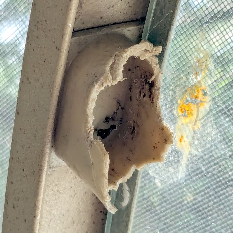
The original brackets had, over uncounted years, deteriorated:
Glass patio table – failed OEM bracket
Perhaps disintegrated would be a better description:
Glass patio table – crumbled OEM bracket
Each leg has a pair of rusted 1-½ inch ¼-20 screws holding it to the central ring. As expected, seven of the eight screws came out easily enough, with the last one requiring an overnight soak in Kroil penetrating oil plus percussive persuasion:
Glass patio table – jammed screw
The four legs had three different screws holding them to the brackets, so I drilled out the holes and squished M5 rivnuts in place:
Glass patio table – M5 rivnut installed
Although it’s not obvious, the end of that tube is beveled with respect to the centerline to put both the top and bottom edges on the table rim inside the bracket. In addition, the tube angles about 10° downward from horizontal, which I did not realize amid the wrecked fittings, so the first bracket model failed instantly as I inserted the leg:
Glass patio table – first bracket test
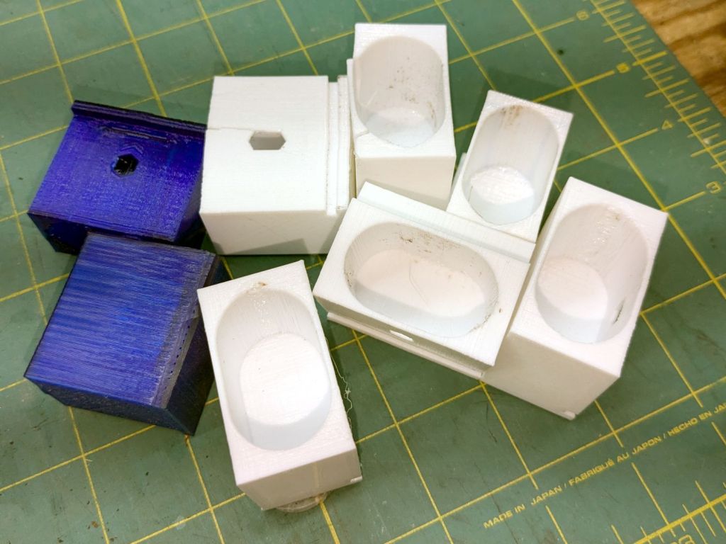
The top & bottom walls of that poor thing were breathtakingly thin (to match the original bracket) and cracked when confronted with the angled tube. I could not measure all the sizes & angles without assembling the table on trial brackets, so getting it right required considerable rapid prototyping:
Glass patio table – failed brackets
Some trigonometry produced a solid model with features rebuilding themselves around the various sizes / angles / offsets:
Glass Top Table – leg bracket – solid model
A sectioned view shows the angled tube position and end chamfer:
Glass Top Table – leg bracket – section view
The OpenSCAD code can produce a sectioned midline slice useful for laser-cut MDF pieces to check the angle:
That eliminated several bad ideas & misconceptions, although trying to balance the leg on a 3 mm MDF snippet was trickier than I expected. In retrospect, gluing a few snippets together would be easier and still faster than trying to print a similar section from the model.
The slightly elongated slot for the M5 screw shows that the original screw holes were not precisely placed or that the tubes were not precisely cut, neither of which come as a surprise. I finally built some slop into the design to eliminate the need for four different blocks keyed to four different legs.
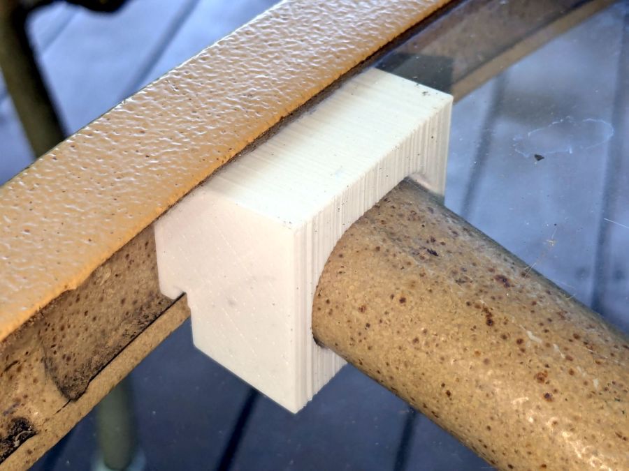
The outer rim, the notch on the bottom, and the tab on the top curve to match the four foot OD glass tabletop, with the inward side & ends remaining flat:
Glass patio table – chunky bracket installed – top
The sector’s difference from a straight line amounts to half a millimeter and improved the fit enough to justify the geometric exercise. The bracket snaps into position with the notch over the table rim and the tab locked in the gap between the glass disk & the rim, although I suspect the weight of the tabletop would keep everything aligned anyway.
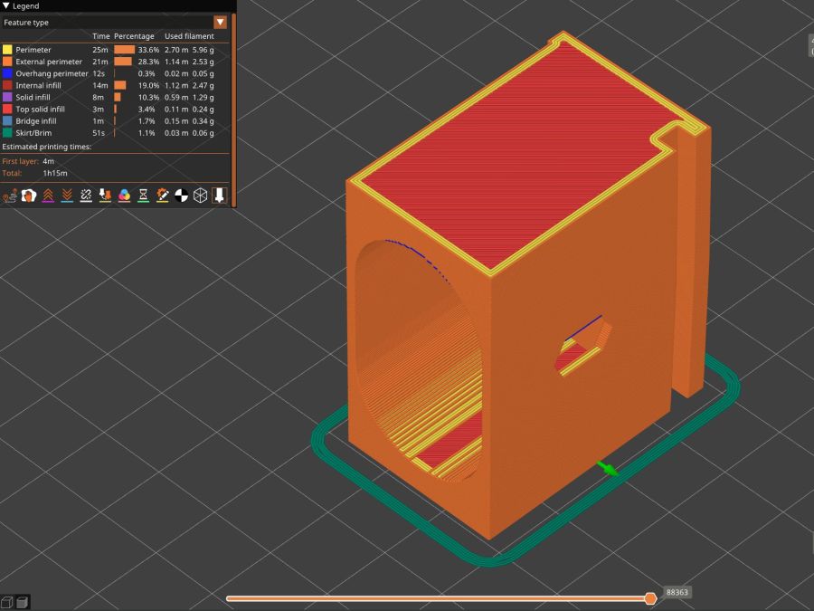
The walls are now at least 4 mm thick and, printed in PETG, came out strong enough to survive assembly and some gentle testing. They’re arranged to print on their side to eliminate support under those slight curves and to align the layers for best strength vertically in the finished bracket:
Glass Top Table – leg bracket – slicer preview
The leg cavity and screw hole built well enough without internal support.
They’re relentlessly rectangular and I’m not going to apologize one little bit.
Now to see how they survive out there on the screened porch.
This file contains hidden or bidirectional Unicode text that may be interpreted or compiled differently than what appears below. To review, open the file in an editor that reveals hidden Unicode characters.
Learn more about bidirectional Unicode characters
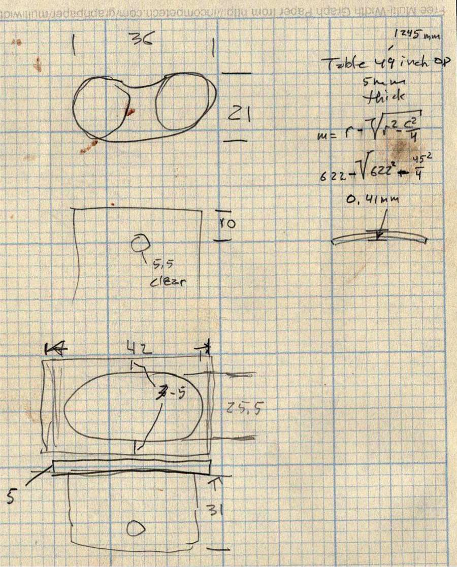
The little wasp has 0.5 mm slots perfectly suited for very light cardboard. It’s missing a few small pieces because at that scale they just don’t matter.
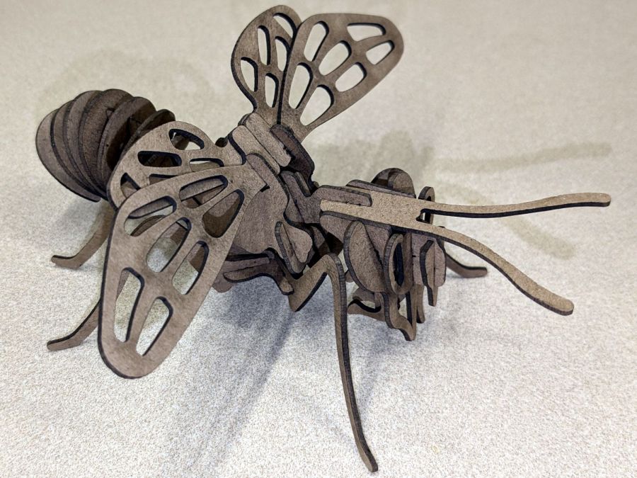
The chunky bee uses the familiar 1.4 mm chipboard:
Bee – right front
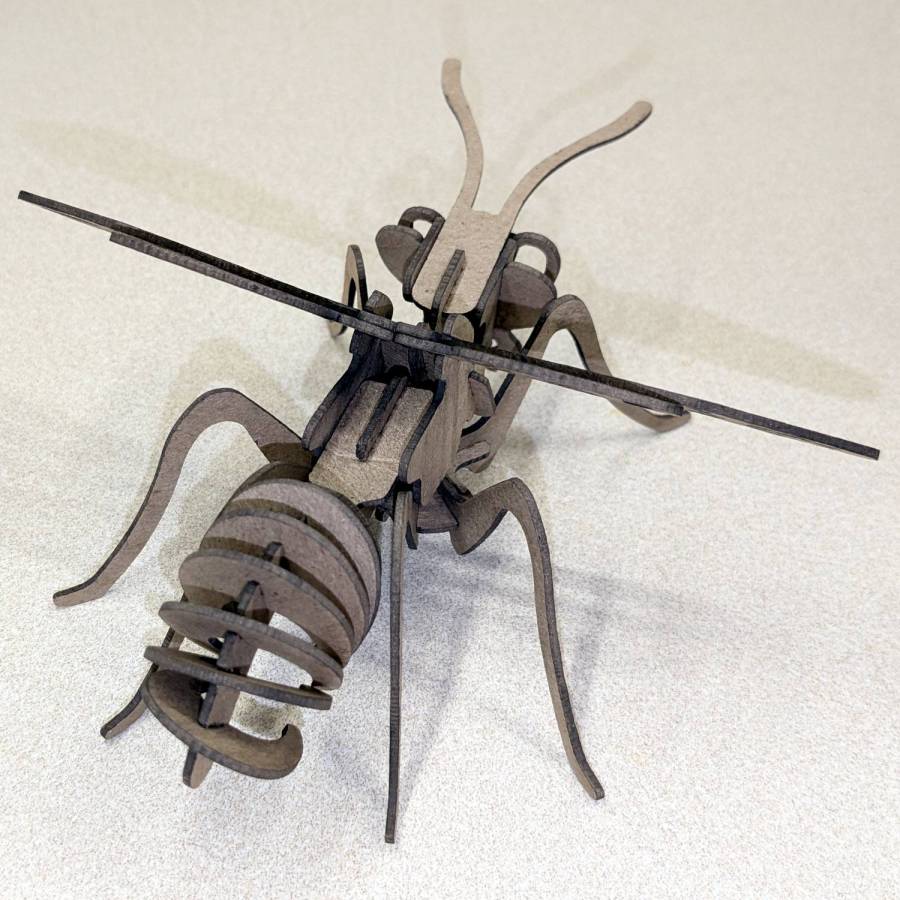
A rear view to remind me where that long flat slab fits:
Bee – right rear
They have far too many pieces for mass production!
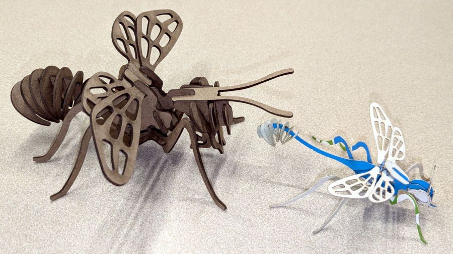
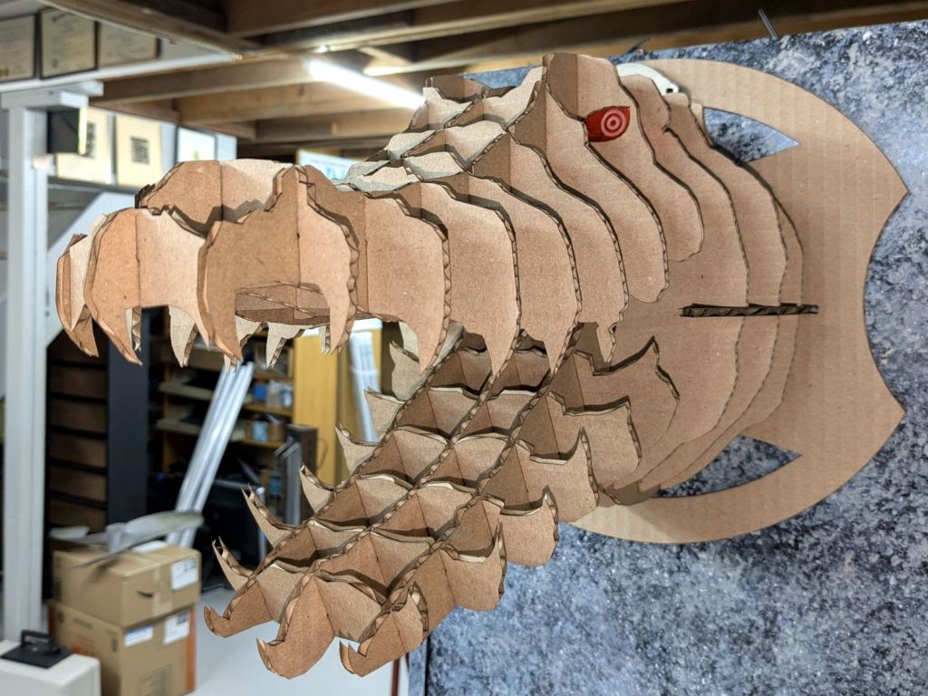
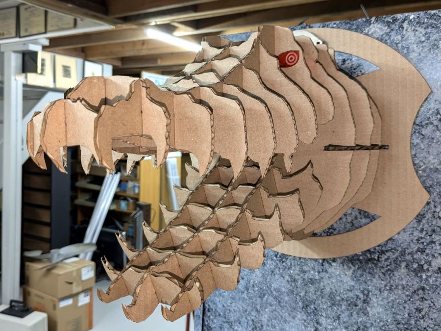
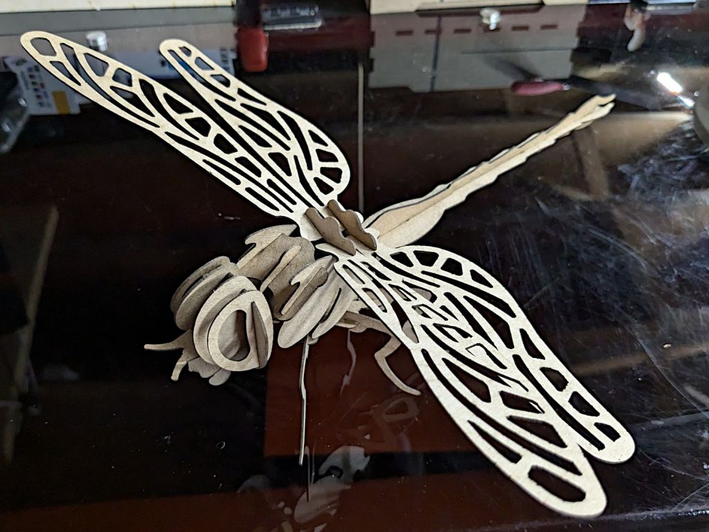
It’s about a foot long, which makes one think of those prehistoric insects flying in dense, oxygen-rich air.
Of course, a Dragonfly needs prey, for which a Mosquito should suffice:
Mosquito – assembled
It’s about five inches from needle tip to tail and would certainly put up a stiff fight.
They’re both made from chipboard, with original model slot sizing being Close Enough that I could just resize the whole thing to fit the available sheets.
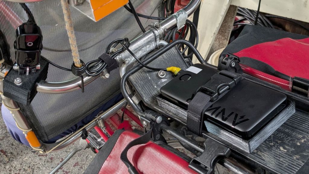
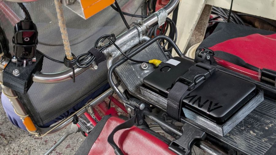
The Anker 325 20K V2 power bank is considerably chunkier, as befits its 20,000 mA·hr cell capacity (although the fine print says 12,500 mA·hr output):
Anker 20K V2 Power Bank – installed
The white tape stripe on the top marks the USB port on the end to reduce the fumbling involved in an out-of-sight socket. There’s also a USB-C port on that end for both charging the pack and powering other devices.
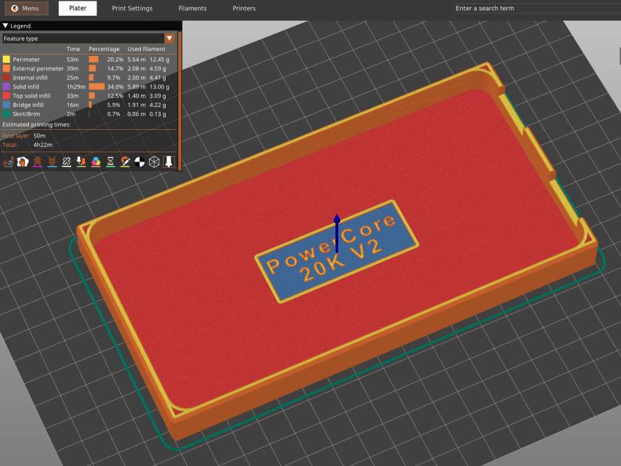
The new mounting cradle descends directly from the 13000 cradle:
Anker 325 20KV2 Power Bank – slicer preview
The model includes a projection of the battery on the XY plane for export to an SVG file suitable for laser-cutting an EVA foam pad to cushion the bumps.