Ed Nisley's Blog: Shop notes, electronics, firmware, machinery, 3D printing, laser cuttery, and curiosities. Contents: 100% human thinking, 0% AI slop.
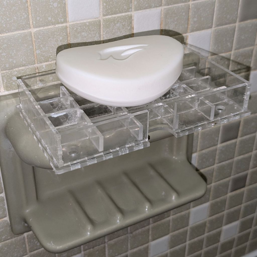
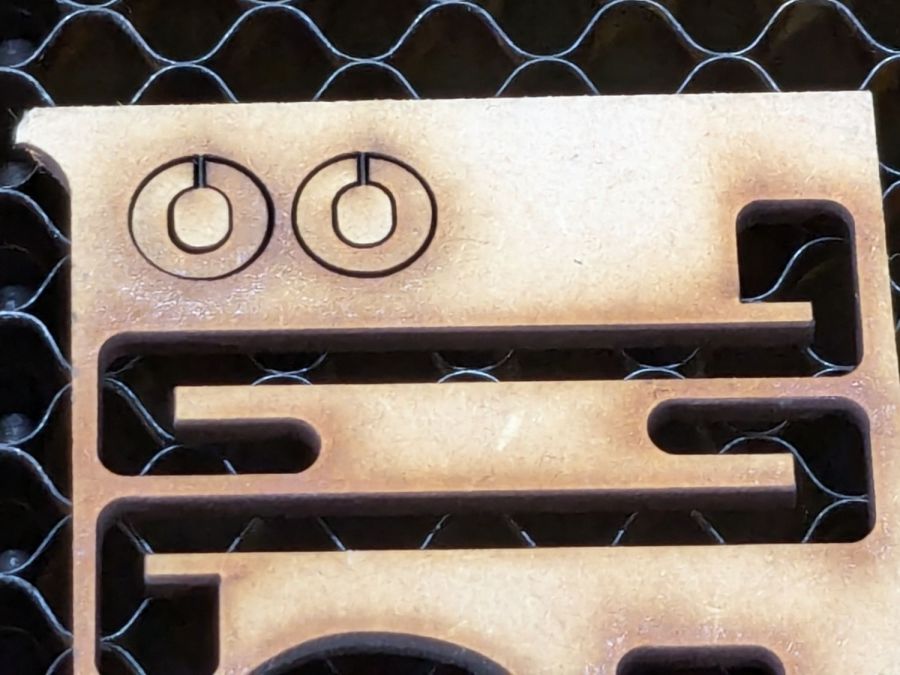
As expected, the adhesive foam strips I used on the bathtub soap tray didn’t survive continued exposure to hot soapy water, so Version 2 includes hooks securing it to the ceramic soap tray and a few other tweaks:
Bathtub Soap Tray – V2 – LightBurn layout
The view from the top:
Soap Tray V2 – top
The hooks are more visible from the bottom, as is the 10 AWG copper wire preventing the whole affair from rotating around the ceramic handle from the weight of the soap bar:
Soap Tray V2 – bottom
Ignore the usual crud you’ll find on your ceramic soap tray, too.
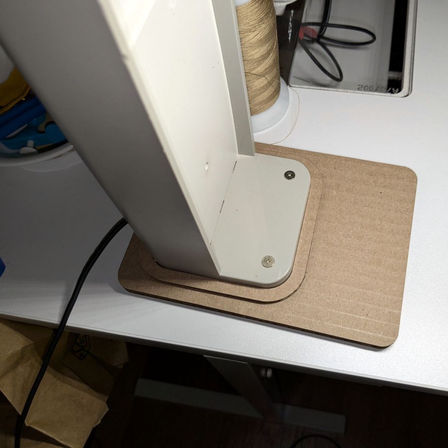
It’s not particularly elegant, what with being cardboard, but it’s a proof of concept that will determine the final size.
The top layer is a ring around the lamp pedestal for a bit of stabilization protecting the four M3 screws holding the base to the lamp. Those screws sit on a 60 mm square, offset 1 mm to the front of the lamp:
NisLite Baseplate – LightBurn layout
Which explains why I typically make the first few versions of anything out of cardboard.
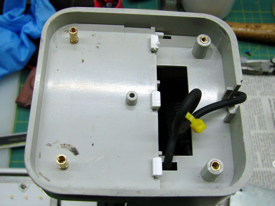
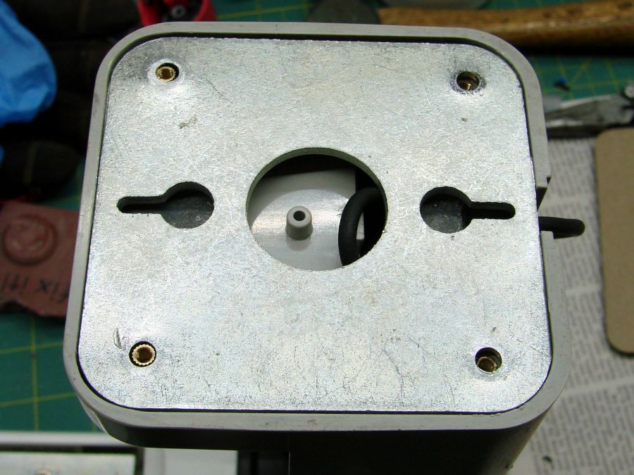
For the record, those inserts look like this:
Converted Ottlite – brass inserts
A pair of very flat-head M3 screws hold the front inserts in place through holes match-drilled in the remains of the bosses I’d long ago epoxied in place. I pressed the rear inserts in place by misusing the drill press, as the lamp is much too tall for the heat setter.
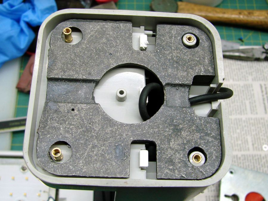
Then comes the iron base weight:
Converted Ottlite – iron weight
And then the steel outer plate:
Converted Ottlite – steel cover plate
The new base plate gets a ring around its perimeter for clearance under the four pan head M3 screws into the inserts.
If the cardboard base is stable enough, we’ll do an acrylic version in cheerful primary colors.
The LightBurn layout in SVG format as a GitHub Gist:
The test patterns will require power / speed tweakage to properly mark cardboard on other machines. The vector boxes are about 1.5 mm wide: these are small differences in small patterns.
The setup for both LightBurn 1.7 RC-13 and RDWorks 8.01.65:
The engraved patterns run at 500 mm/s & 20% power
The lines & letters run at 100 mm/s & 8% Min – 9% Max power
All on white cardboard, with image contrast blown out
Scanning offset = 0.2 mm = the usual setting for my machine
In LightBurn:
Scanning Offset 0.2 – LightBurn
In RDWorks:
Scanning Offset 0.2 – RDWorks
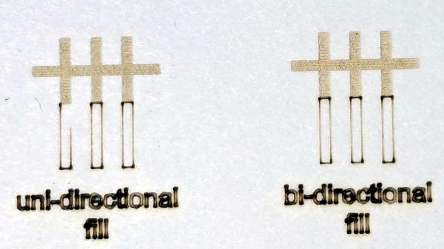
The slight shift to the left in the LightBurn results shows LB does not shift the uni-directional pattern to line up with the vector shape as RDWorks does, which is what started the forum thread.
Scanning offset = 1.0 mm to accentuate the difference, while shredding the bi-direction pattern as expected.
LightBurn’s uni-directional engraved pattern is still in the same slightly leftward-shifted position relative to the vectors, showing the offset value has not been applied:
Scanning Offset 1.0 – LightBurn
RDWorks definitely applies the offset in both modes:
Scanning Offset 1.0 – RDWorks
I do not know why RDWorks did not output the final “l” over there on the right, but it did so on some (not all) of the patterns while setting things up. The jank is strong with it.
So having LightBurn apply the same offset value for both uni- and bi-directional engravings would fix the (slight) offset in my machine. I think it will also fix the much larger misalignment in [the other] machine in that forum discussion.
The whole problem seems to arise from the response time of the HV power supply / laser tube: the position of the left & right edges of the scanned output line depend critically on the rising and falling edges of the current applied to the tube and its power output.
Being me, of course, makes me want a different offset value applied to the uni-directional case, just for fine tuning. Which would require a duplicate offset-per-speed table and that looks like a UX disaster comin’ on strong.
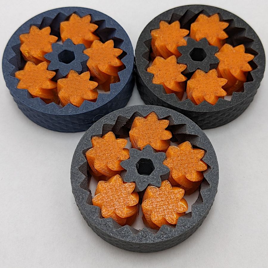
The general idea of a light box is (wait for it) a uniform background in a box full of bright light:
Light Box – overview
Obviously, this is a low-budget light box, but it makes perfect sense if you already have an essentially unlimited supply of moving boxes, 11×17 inch plotter paper, and a couple of photo / video lights lying around.
A two-layer cardboard ring glued to the top keeps the light from sliding off the box and stiffens the gaping hole letting the light shine through.
You’d normally use a fabric background to get rid of those ugly gaps around the edges and a larger box would be better, so this is along the lines of a proof-of-concept.
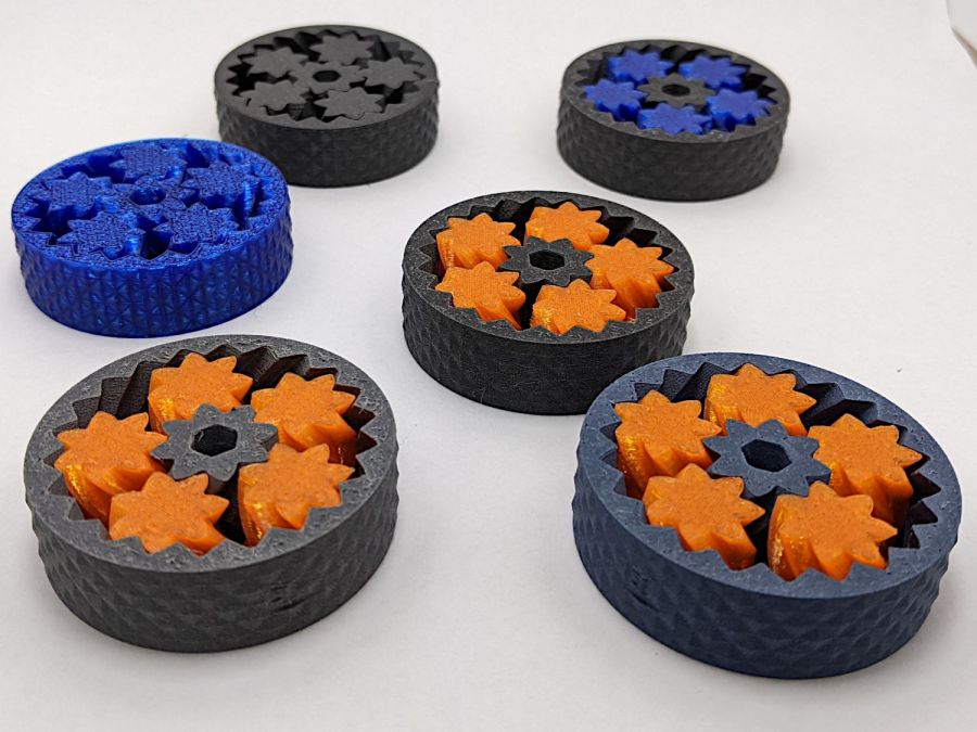
In this day and age, you’d normally use a phone camera:
Light Box – gears overview – DOF
The lens on my Pixel 6a has a fixed focal length (around 4.4 mm = 27 mm equivalent) and a fixed f/1.8 (-ish) aperture, producing a razor-thin depth of field at the rear of the front gears. Note the fuzzy gears in the background, all of three inches away, and the slightly fuzzy front edge of the front gears. The camera’s digital zoom doesn’t help matters in the least, despite the AI-powered interpolation.
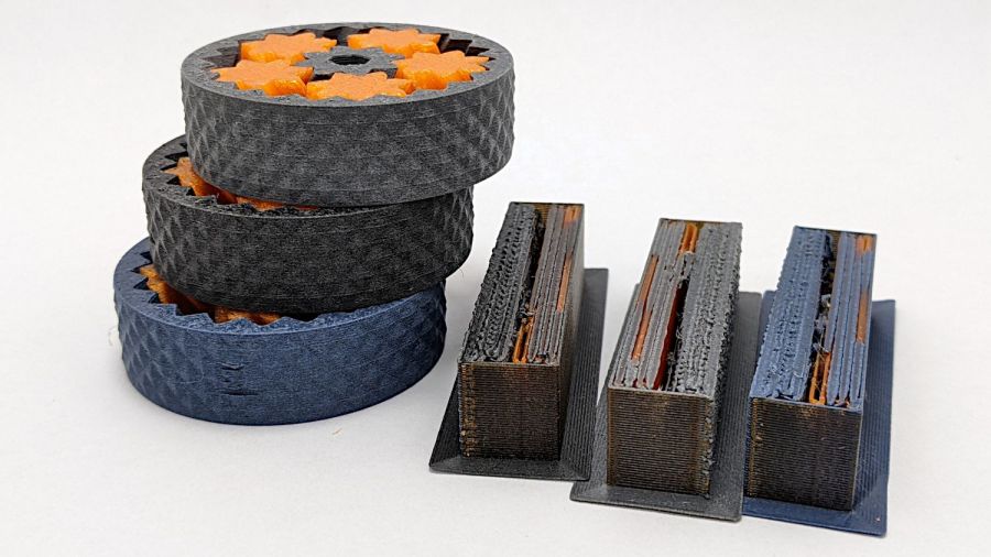
Keeping things close together helps, although the far end of the wipe towers and the rear of the gears lose detail:
Light Box – gears stacked
Looking from above also helps a little, but a top viewing port would reduce the skewed perspective:
Light Box – gears detail – DOF
Shallow DOF keeps your attention on the foreground, which is why real photographers use it for portraits:
Light Box – gears standing – DOF
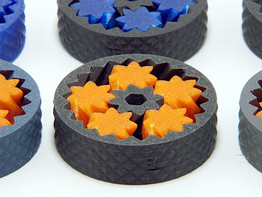
The camera, an ancient Sony DSC-H5 with a zoom lens going down to f/8, still does nice work through a 2× macro adapter lens:
Light Box – gear detail – top light
The DOF is still narrow, but at least the entire front gear is in focus.
Adding a front light picks out the knurling:
Light Box – gears detail – front light
The results definitely look better than before, but it’ll take a bit of getting used to traipsing to the Basement Laboratory for every photo …
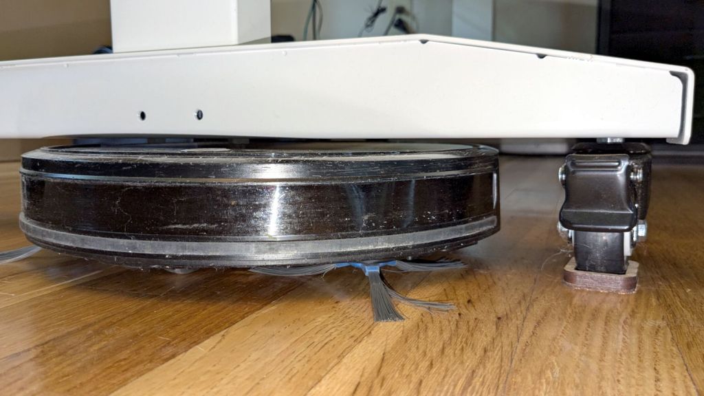
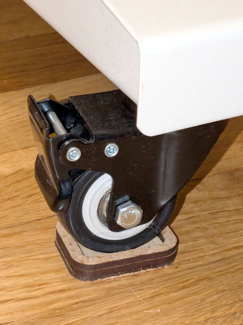
The flat robot vacuum assigned to clean the floors around here would occasionally get stuck under the leg of my Husky workbench-as-desk and fail to complete its mission. Living in the future makes solving that problem a matter of minutes:
Husky workbench caster feet – installed
The upper rim captures the locked-in-place wheel in a 35×25 mm recess atop the middle 45×35 mm slab, with a 2.5 mm cork layer on the bottom. Laser-cut, of course, glued with ordinary yellow wood glue, and clamped for about half of a Squidwrench remote meeting.
Raising the desk by 5.5 mm gives the Flat One juuust enough clearance to scuttle under there:
In the process of fixing something else, I discovered my favorite desktop razor knife had a loose blade. There being nothing like a new problem to take one’s mind off all one’s previous problems, I obviously had to fix it before proceeding:
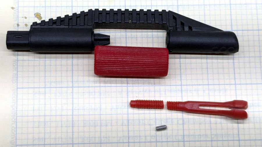
Razor Knife – broken collet thread
Come to find out the plastic screw tightening the blade collet had snapped. The remaining stub stuck out from the red ribbed nut just far enough to prevent sliding the nut out of the black plastic body, but jamming a small screwdriver through the body got enough traction to unscrew the stub. It’s threaded 8-32, despite being old enough to be Made in Taiwan.
The red plastic feels like HDPE or a similar un-glue-able material, so it was going to need a mechanical splice. A tiny 2-56 setscrew falls in the class of things my buddy Eks describes as “If your design needs those, you’re doing it wrong”, but sometimes you gotta do what you gotta do.
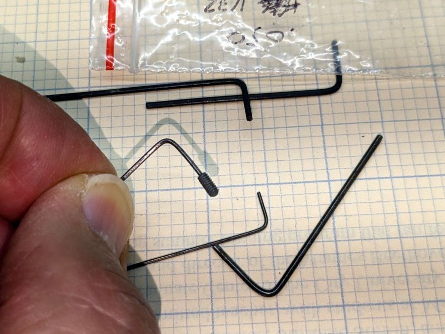
The little wrench in the background measures 28 mils for 0-80 setscrews, of which I have none and don’t expect to get any.
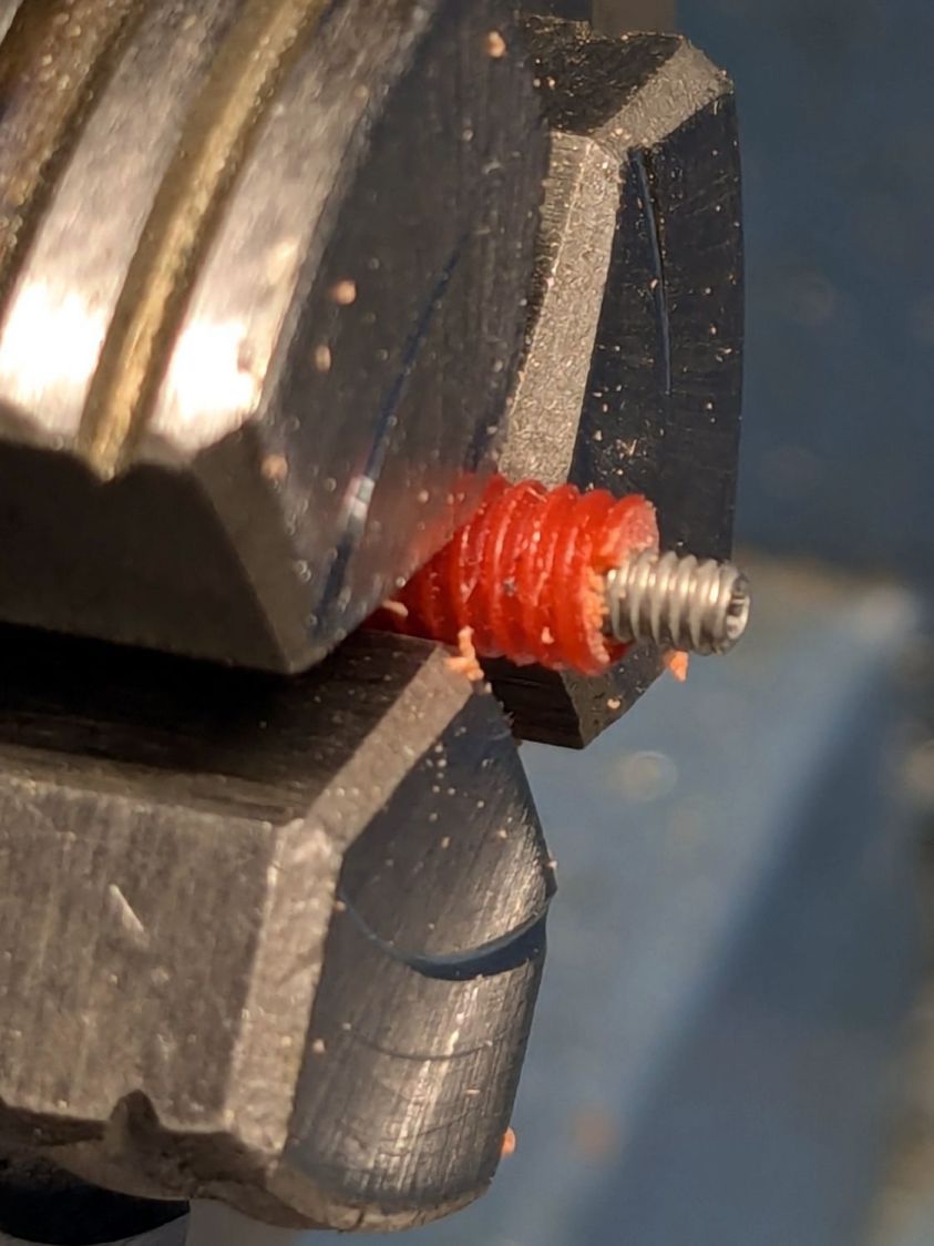
Anyhow, facing, drilling, and tapping the stub proceeded handily:
Razor Knife – setscrew in thread stub
You’d think I hadn’t faced off the end, but you’d be wrong. As far as I can tell, the end of the screw would be happy to break for as long as I’d be willing to try cutting it. Perhaps this indicates why it broke and suggests this repair will be temporary, at best.
Doing the same to the collet required a clamp to fit its slightly oblong body:
That’s aggressive stick-out for a little plastic rod, but sissy cuts saved the day; it faced / drilled / tapped easily enough:
Razor Knife – collet repair parts
Despite the non-glue-able plastic, I tucked some JB PlasticBonder into the recesses, screwed everything together, and coerced the 8-32 threads into alignment inside the plastic nut:
Razor Knife – collet thread alignment
Reassemble in reverse order after the adhesive set up:
The fixture in the lower left is just an MDF square with a 15 mm post of more MDF glued in the middle to align the pieces. The white disk is the adhesive sheet, cut to 119 mm OD to leave half a millimeter clear around the outer edge, thus avoiding embarrassing stickiness.
Peel one side of the adhesive sheet and drop it over the post sticky side up:
Double-faced DVD coaster – adhesive sheet ready
Drop one of the DVDs over it, label side down:
Double-faced DVD coaster – first disc on adhesive
Lift it off, peel the other side of the adhesive sheet, put it over the post sticky side up, and drop the other DVD on top:
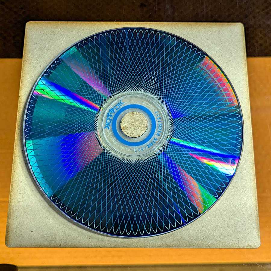
Double-faced DVD coaster – finished
The data side of the discs has a 0.3 mm raised rim just inside the track zone, so they don’t sit exactly flat on the table and expect a slightly concave lower surface on the mug / glass / cup. Neither of those seem like dealbreakers thus far, although I’m sure somebody will object.
A ring or two of general-purpose glue, along the lines of E6000 urethane, would be significantly less fussy than cutting adhesive sheets.


