Ed Nisley's Blog: Shop notes, electronics, firmware, machinery, 3D printing, laser cuttery, and curiosities. Contents: 100% human thinking, 0% AI slop.
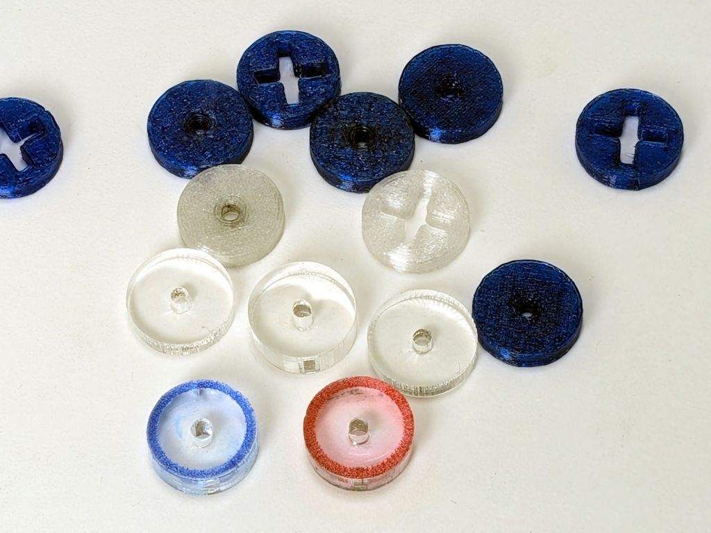
So the engraved ring on the two in the front row carries a cheerful Sharpie color to make them stand out. I wanted to use fluorescent acrylic, but I don’t have any 4 mm sheets and stacking a pair of 3 mm sheets → 6 mm will be too thick for the pencil tip.
What looks like dirt on the red guide comes from internal reflections or the lack thereof: it’s perfectly transparent in person, honest.
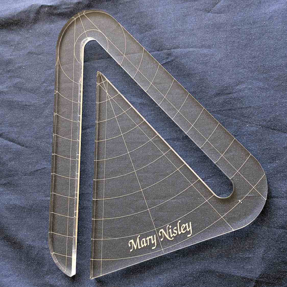
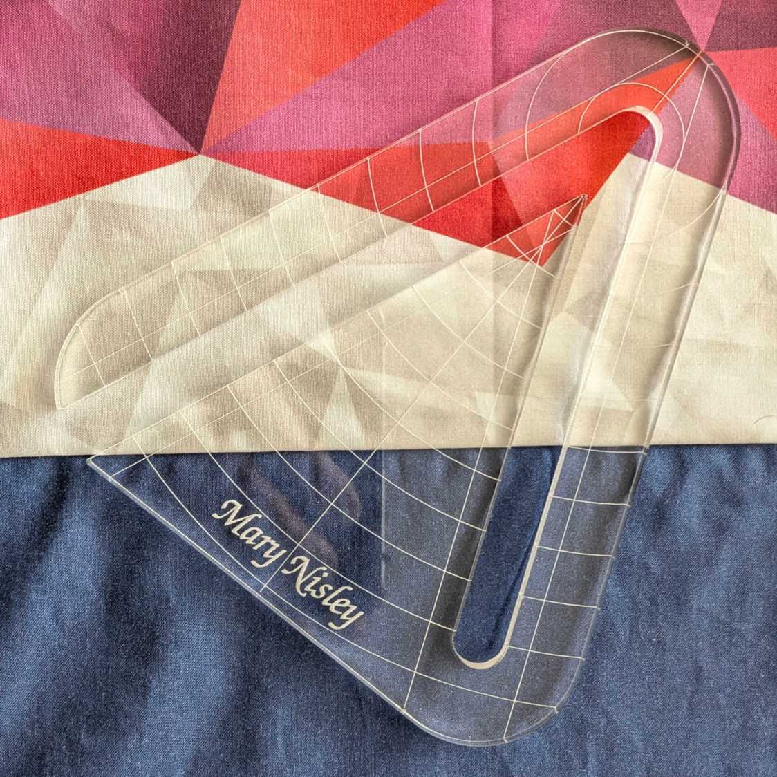
Mary’s current quilt project has a corner design with an essentially infinite number of 45° triangles, which another custom ruler will simplify:
45° Quilting Ruler – finished
That’s the end result of several iterations, proceeding from doodles to sketches to increasingly accurate laser-cut prototypes:
45° Quilting Ruler – prototypes
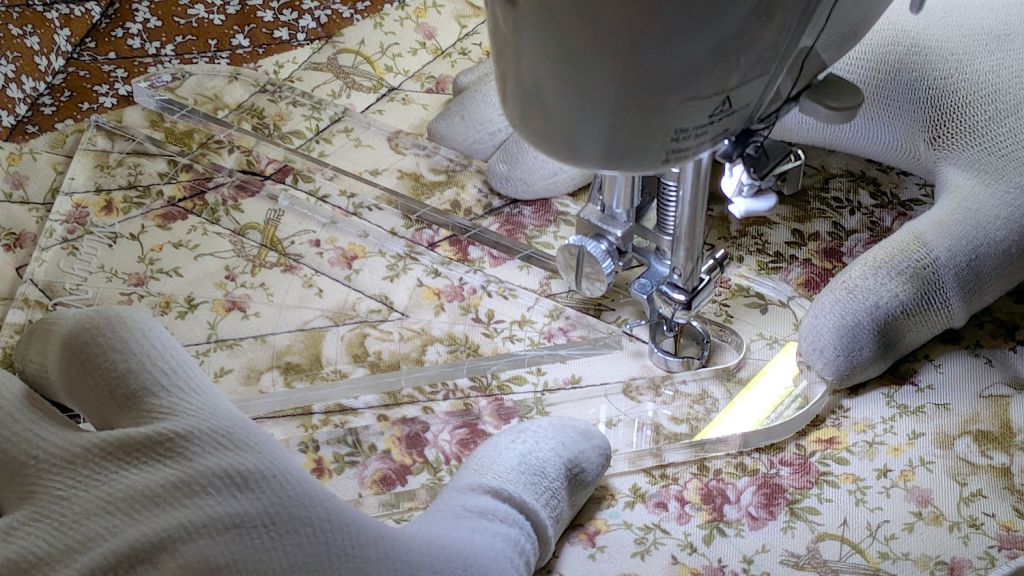
A “ruler” in quilting parlance is a thing guiding the sewing machine’s “ruler foot” across the fabric (or, for sit-down machines, the fabric under the foot) in specific directions:
45° Quilting Ruler – in use
That’s a practice quilt on scrap fabric: quilters need prototypes, too!
The foot is 0.5 inch OD, within a reasonable tolerance, which accounts for the slot width in the ruler. It’s also intended to run against 1/4 inch thick rulers, which accounts for the thickness of that slab of acrylic.
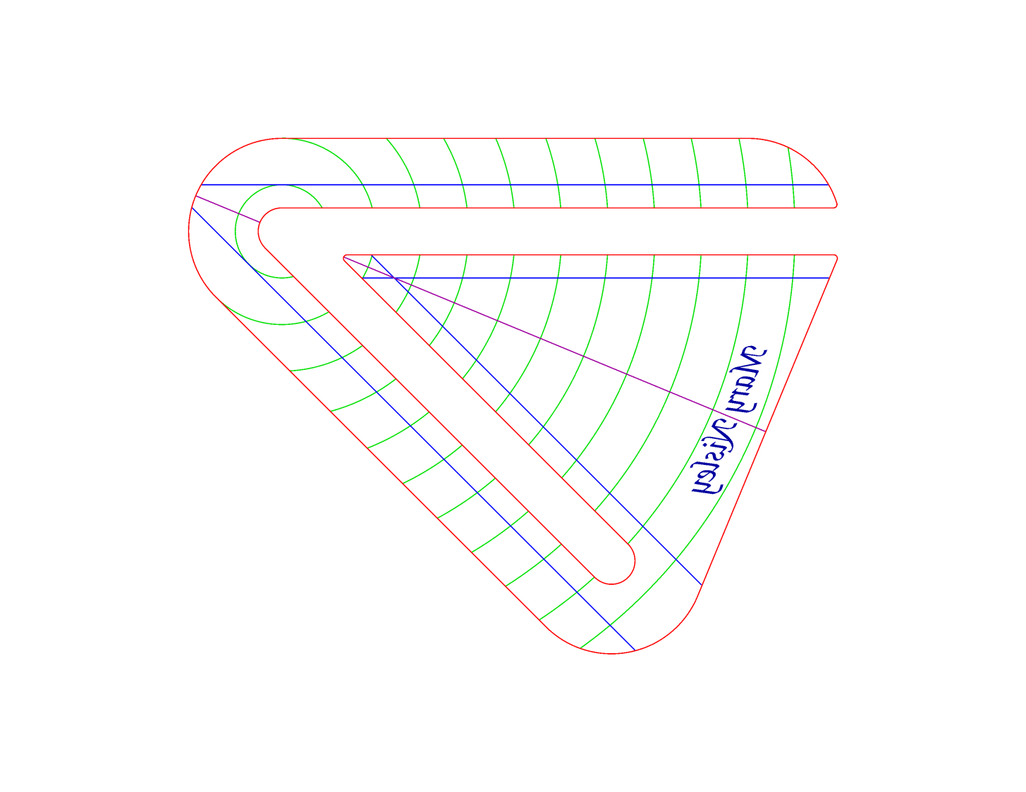
The engraved lines & arcs are on the bottom of the ruler to eliminate parallax errors against the fabric, so the bottom is upward and the text is mirrored for the laser:
45° Quilting Ruler – cutting
Although fluorescent green acrylic may have higher visibility, clear seems adequate for the fabric in question:
45° Quilting Ruler – colored fabric
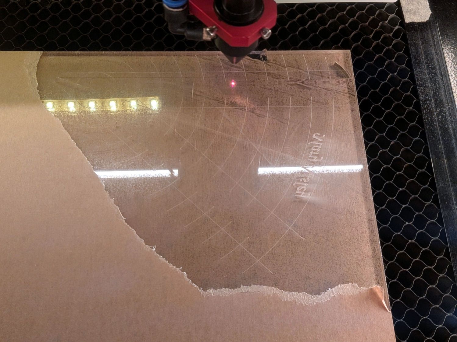
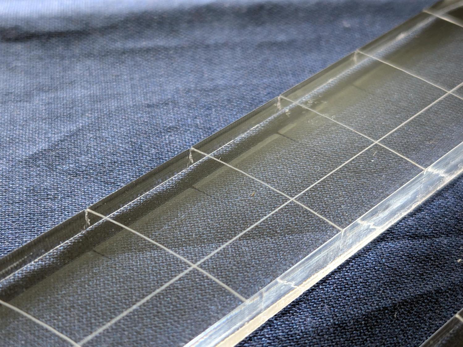
I very carefully trimmed the arcs against the ruler outline using LightBurn’s Cut Shapes, which turned out to be a Bad Idea™, because the high-current pulse as the laser fires causes a visible puncture wound at the still-to-be-cut edge:
45° Quilting Ruler – edge damage
Those are not straight lines and the plastic isn’t bent!
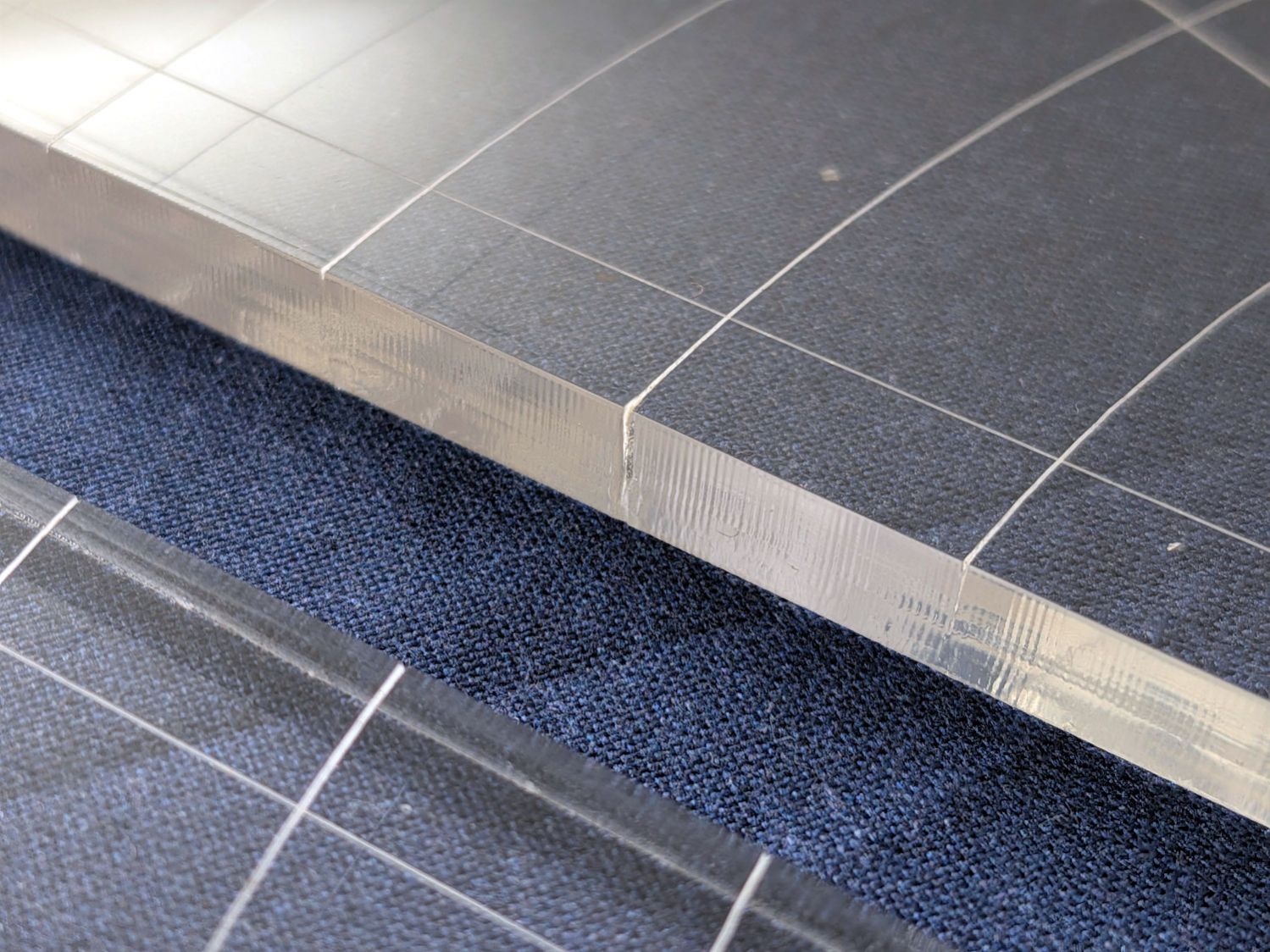
A closer look:
45° Quilting Ruler – edge damage – detail
The arcs without wounds started from their other end and stopped at the edge, which is perfectly fine.
The wounds are unsightly, not structural, but the next time around I’ll extend the markings a millimeter beyond the edges into the scrap material.
The overall design looks busier than it is, because I put different features on different layers in case they needed different settings:
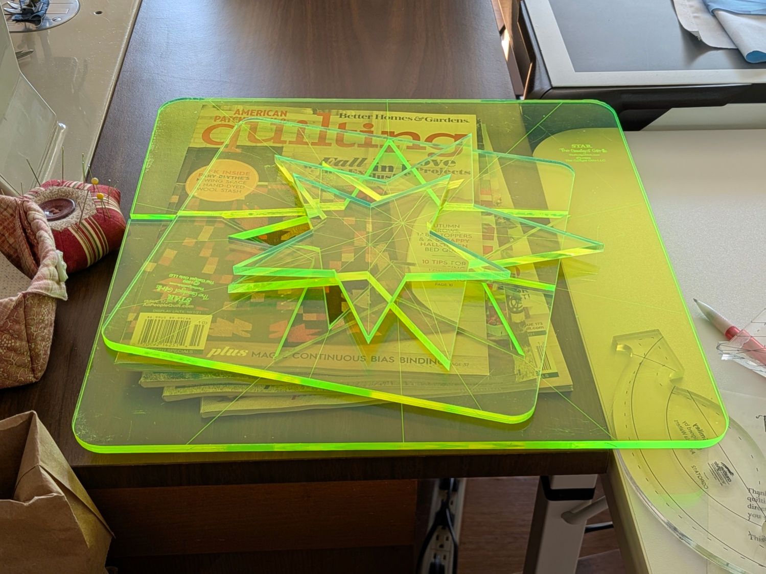
Mary picked up a pair of Star quilting rulers from the Quilting Guild’s “exchange” table:
Star quilting ruler – finished
They’re 1/4 inch laser-cut acrylic slabs dating back to the turn of the millennium, when laser cuttery wasn’t nearly as common as today. Apparently, the (now long gone) Gadget Girls had a problem with their laser: the larger star had eight of its ten lines not cut completely through the acrylic. The protective paper on the back had small perforations along a few of the lines, but nothing for most of them.
Well, I can fix that.
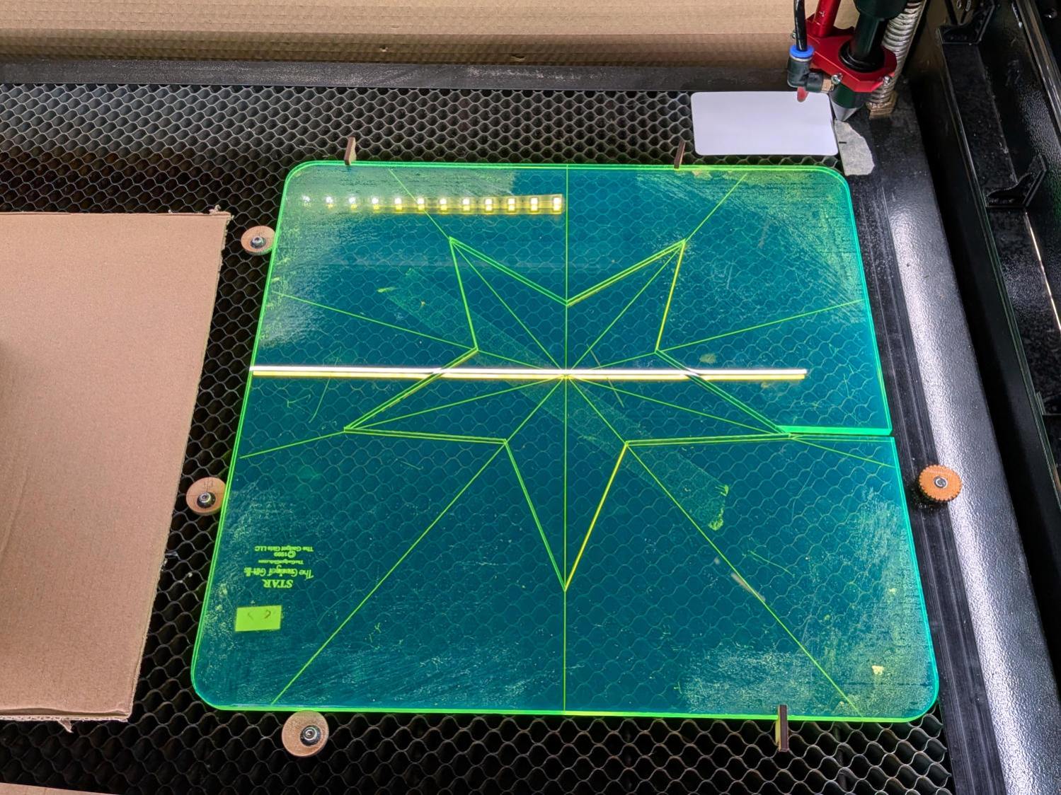
Lay the slab on the platform and lock it in place so it cannot move:
Star quilting ruler – laser setup
That’s with the original bottom side facing upward, so the laser beam will hit the uncut part of the lines.
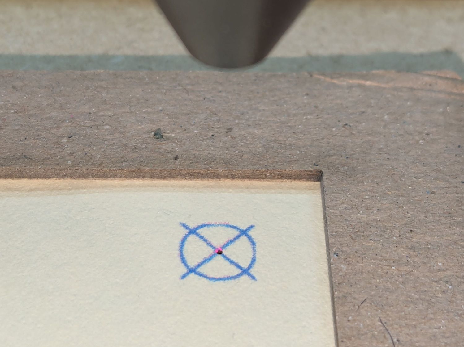
Focus the laser atop some scrap 1/4 inch acrylic, then verify the red dot pointer is exactly concentric with the CO₂ beam by firing a test pulse, as in this punched card:
Red dot vs printed target vs laser spot alignment
Adjust as needed.
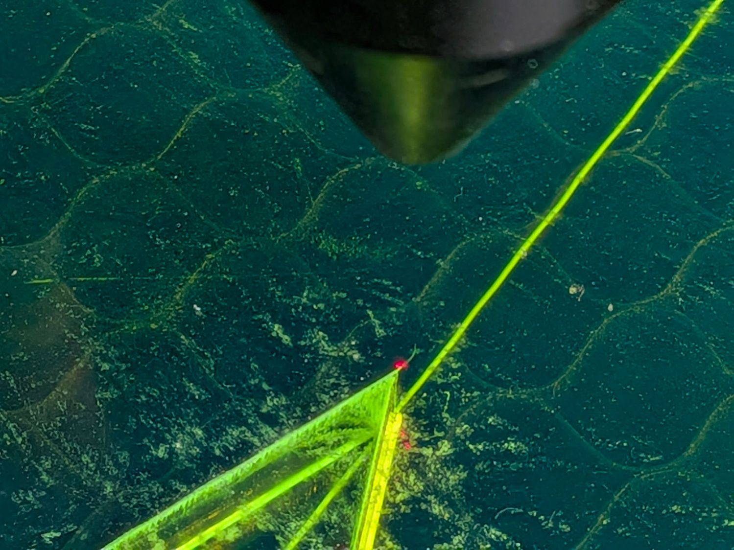
Jog the laser to put the red dot pointer exactly at a star point:
Star quilting ruler – laser point alignment
Hit Get Position in the Laser window so LightBurn knows where the laser head is located.
I’ve added the targets I normally use for LightBurn’s Print and Cut alignment to its Art Library, so I dragged one to the workspace, then hit Move to Laser Position to snap the target directly onto that point of the star.
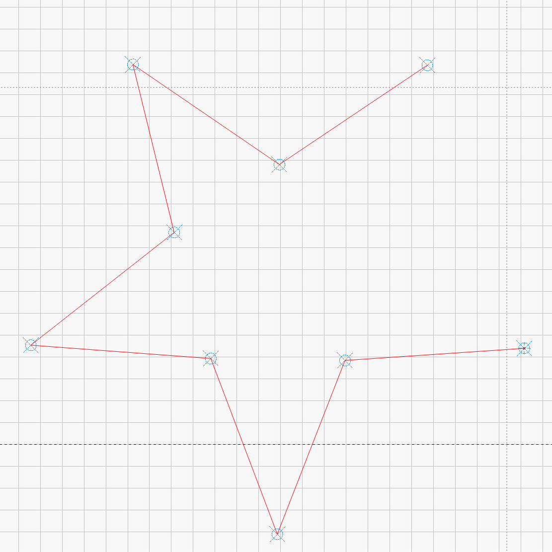
Repeat for vertices along the star, then draw a multi-segment line = path between the target centers:
Star Ruler Re-cutting – LightBurn layout
That’s one continuous path from the upper right, counterclockwise around the star, ending in the center right. The missing pair of lines (and the vertex between them) were already cut, so I didn’t need to locate them.
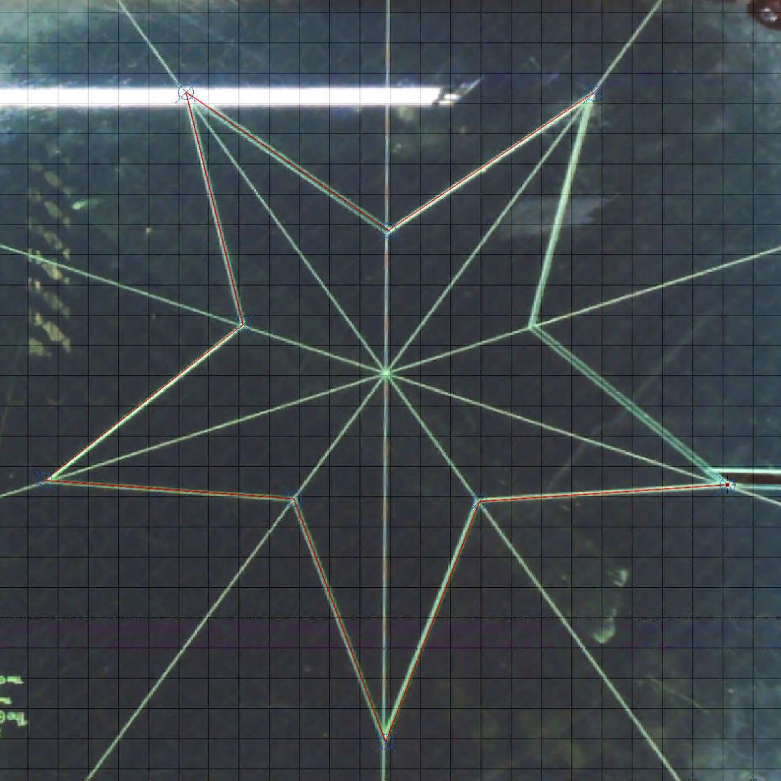
The camera view shows the alignment, although IMO the camera simply isn’t capable of such finicky alignment:
Star Ruler Re-cutting – LightBurn layout overlay
As a confidence builder, I selected each target, moved the laser to that point, then fired a test pulse to verify the hole hit the vertex. In most cases, I couldn’t see the hole because it was within the original cut.
My 60 W laser can’t cut through 1/4 inch = 6 mm acrylic in a single pass, so I use a 10 mm/s @ 60% pass to get most of the way through and a 20 mm/s @ 60% pass to complete the cut. That seemed excessive for a mostly cut path, but a single 20 mm/s @ 60% pass didn’t completely clear the uncut sections.
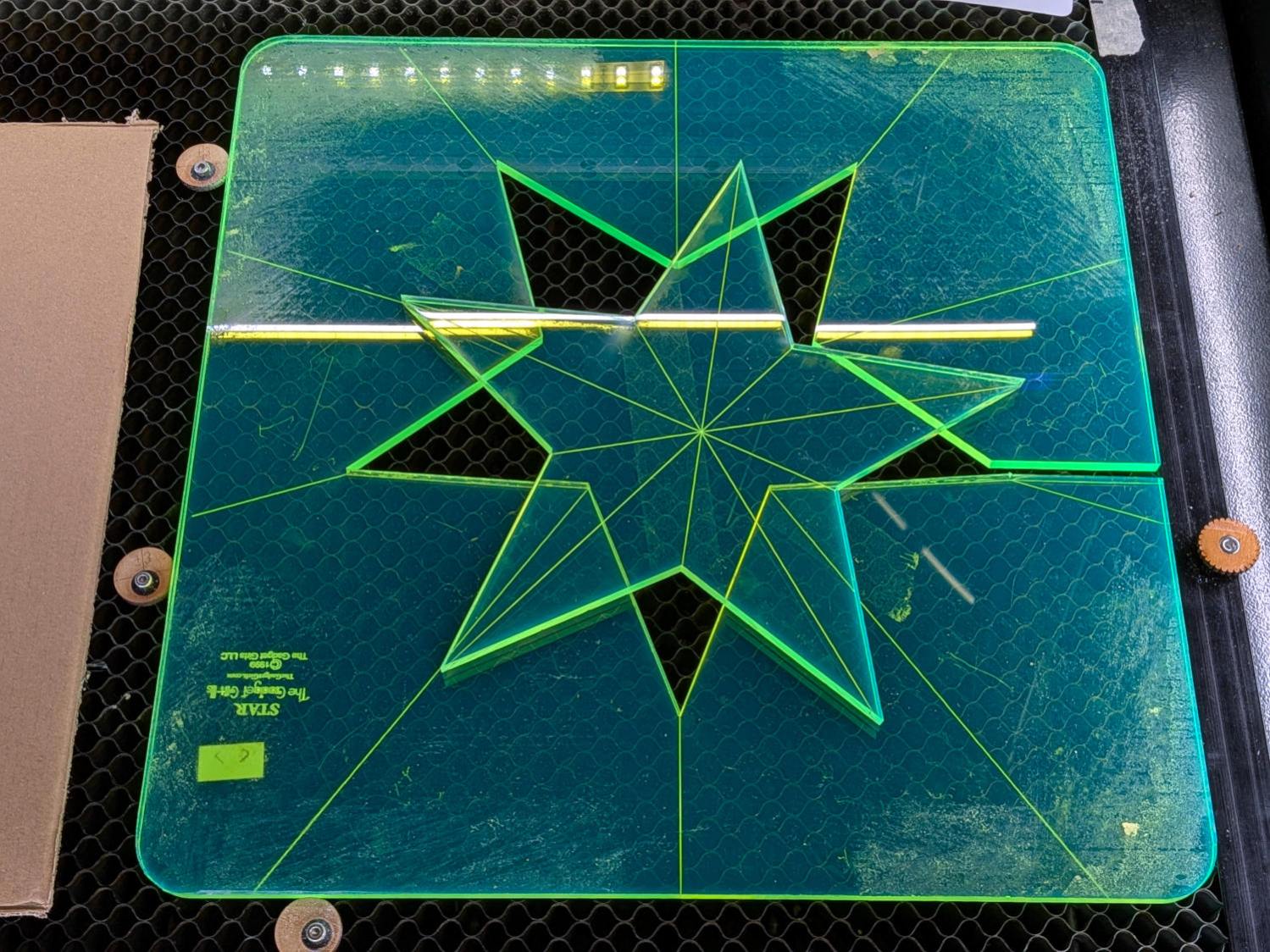
So I used the normal two-pass cut and the star lifted right out:
Star quilting ruler – victory
Happy dance!
Although it is not obvious from the pictures, the star is not symmetric: it fits into the sheet in only one of its ten possible orientations. I will never know if that was a deliberate stylin’ decision or the result of hand layout before CAD spread throughout the land.
I managed to locate the vertices so accurately that the repeated cuts left edges indistinguishable from the original cuts on the two free sides, which was a pleasant surprise.
Mary promises to do something with those stars when she’s done with her current project(s). She may want the slab of acrylic around the large star trimmed into a smaller and more manageable decagon, in which case I will suddenly have a bounty of thick fluorescent green acrylic.
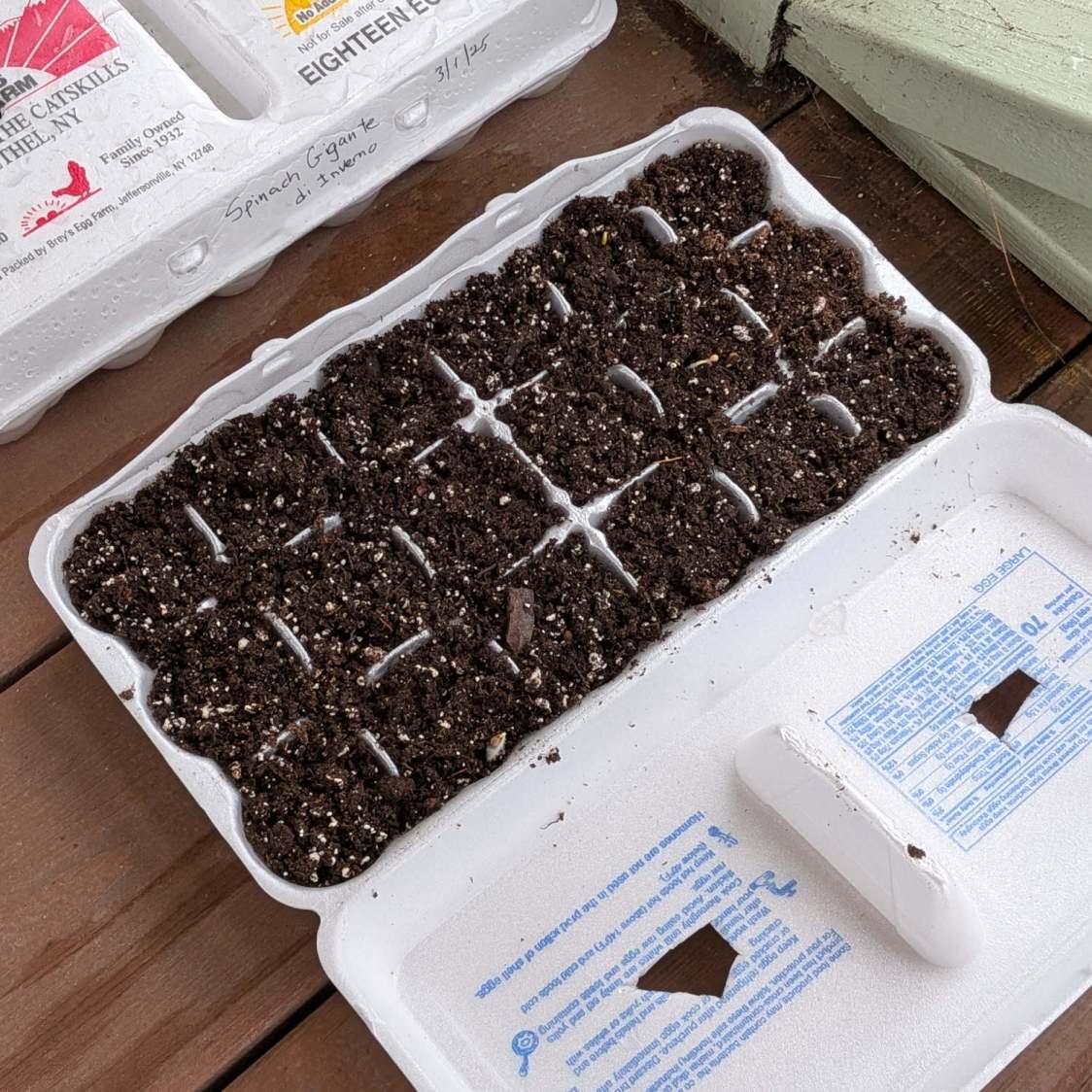
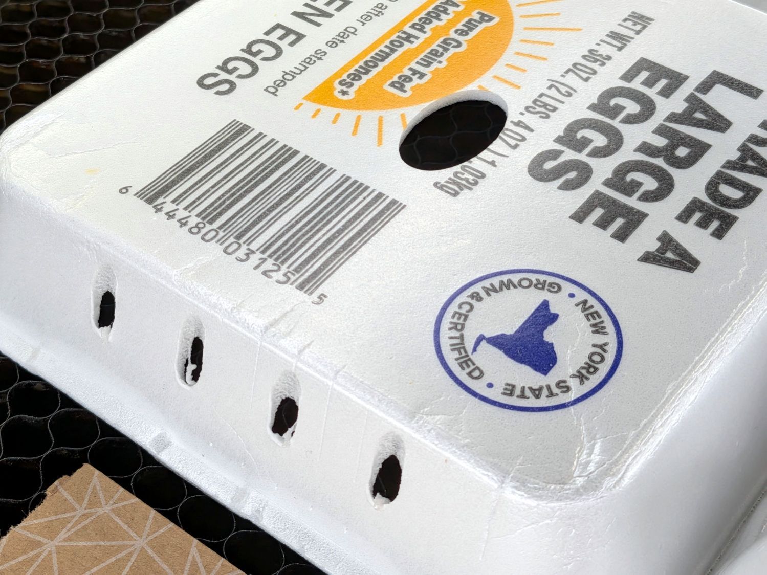
Mary has been using Styrofoam egg cartons to sprout seeds for this year’s garden veggies:
Egg carton sprouter – hand cut
I looked at those artisanal holes and offered to make sprouters with precisely calibrated laser-cut holes.
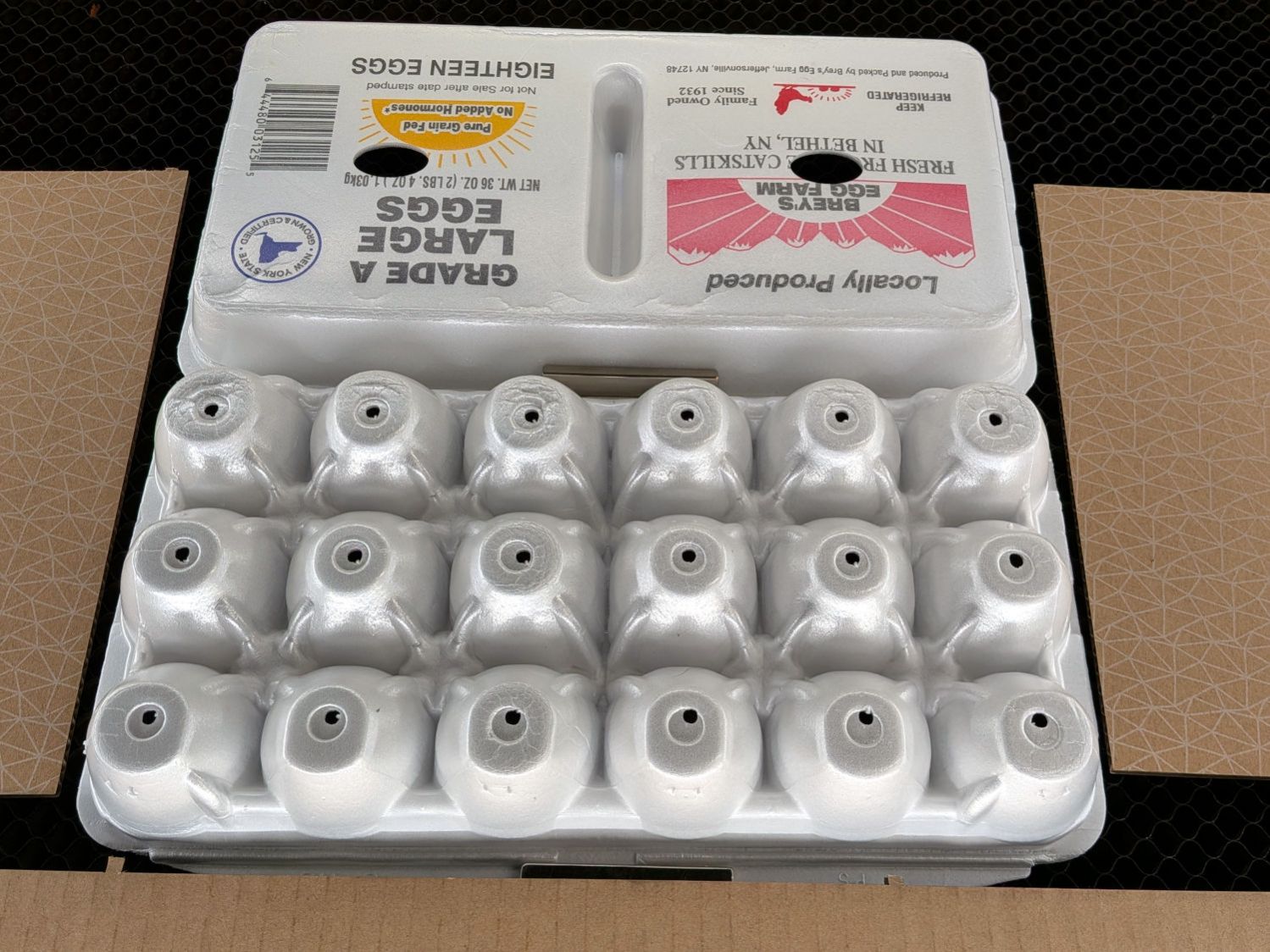
After the laughter died down, this happened:
Egg carton sprouter – lid detail
Each egg compartment has a drainage hole in the bottom:
Egg carton sprouter – on platform
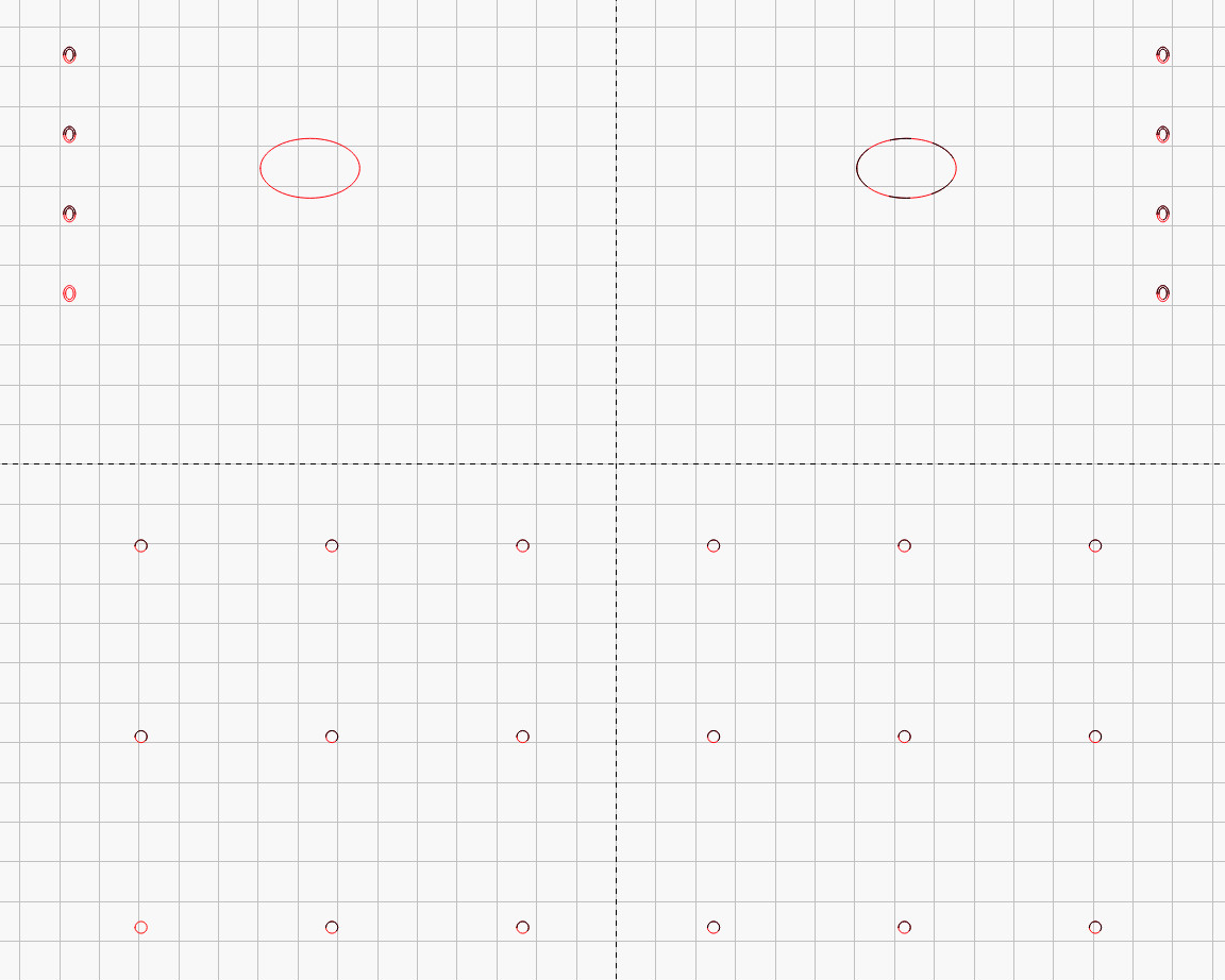
The LightBurn layout has four shapes in three virtual arrays:
Drain holes: 3 mm circle, 6×3 array
Top vents: 25×15 mm oval, 2×1 array
Side vents: concentric 3×4 & 2×3 mm ovals, 2×4 array
Which looks like this:
Egg Carton Sprouter – LightBurn layout
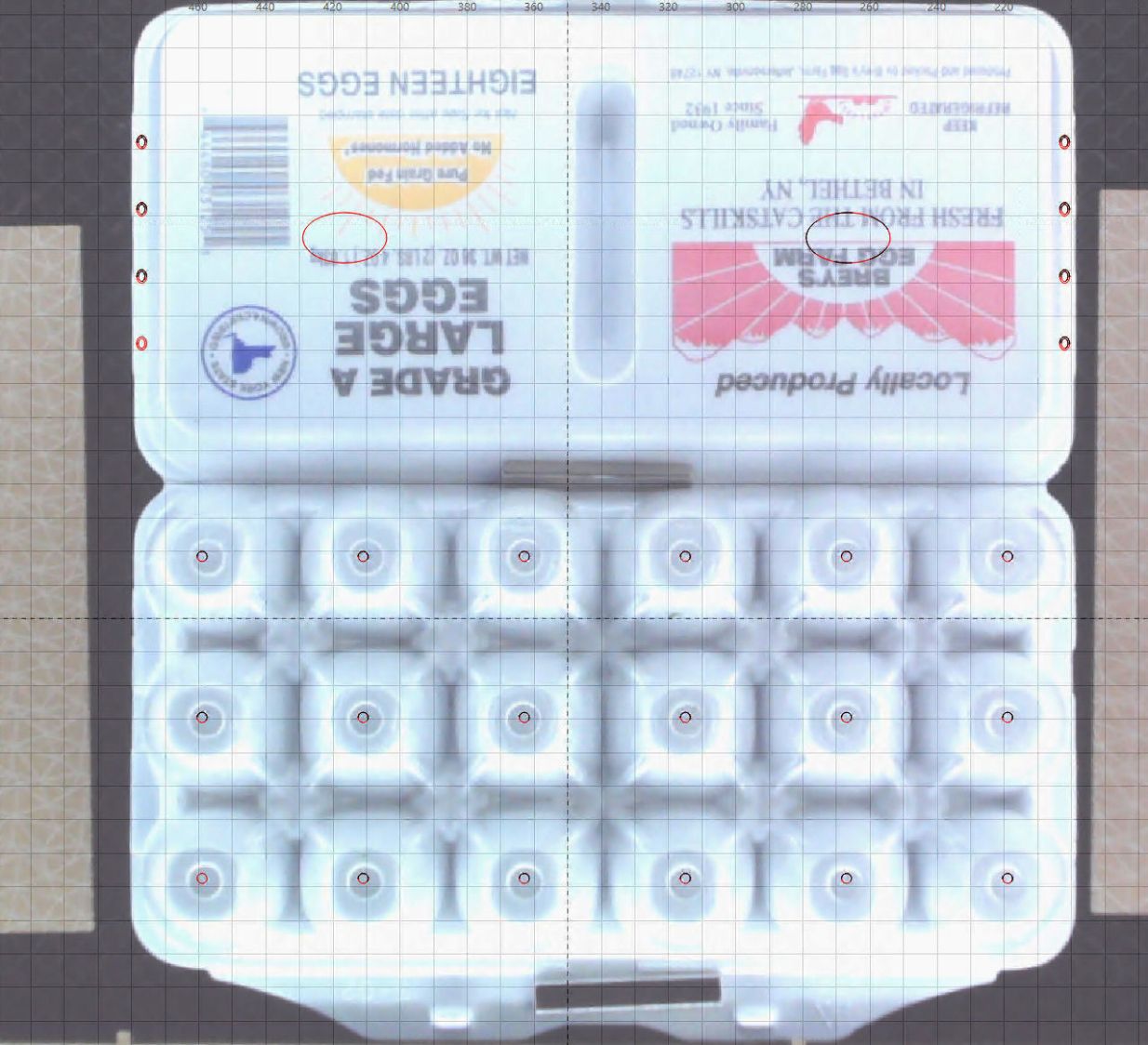
Because this isn’t a high-precision operation, I align the patterns to the carton using the camera:
Egg Carton Sprouter – LightBurn camera alignment
The two halves of the unfolded carton aren’t the same height, which means the top and bottom patterns have different focus levels and must be cut in two operations.
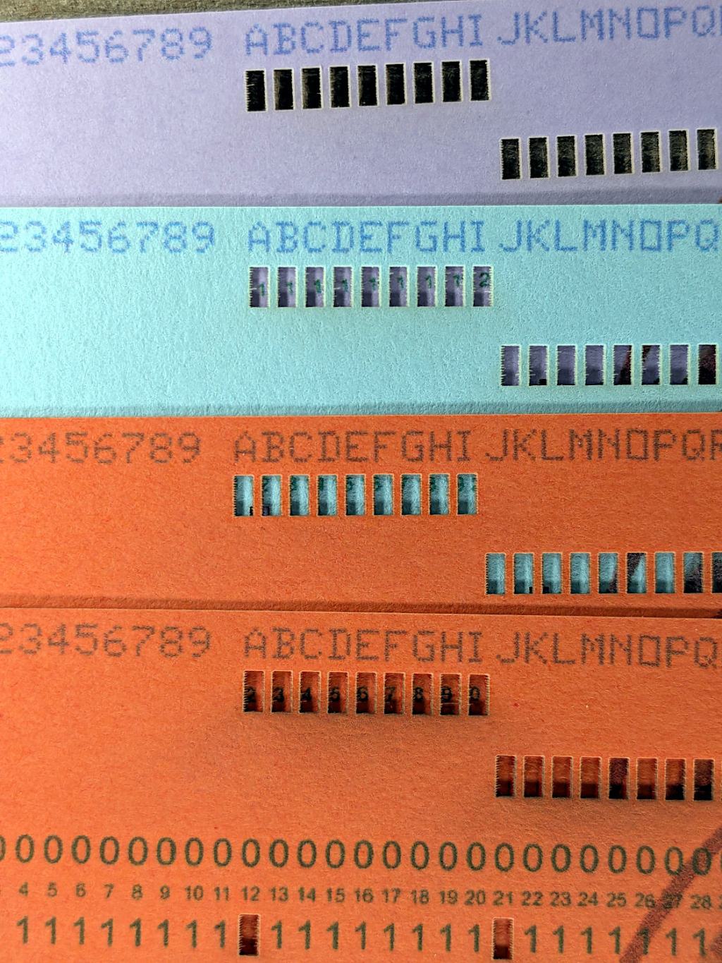
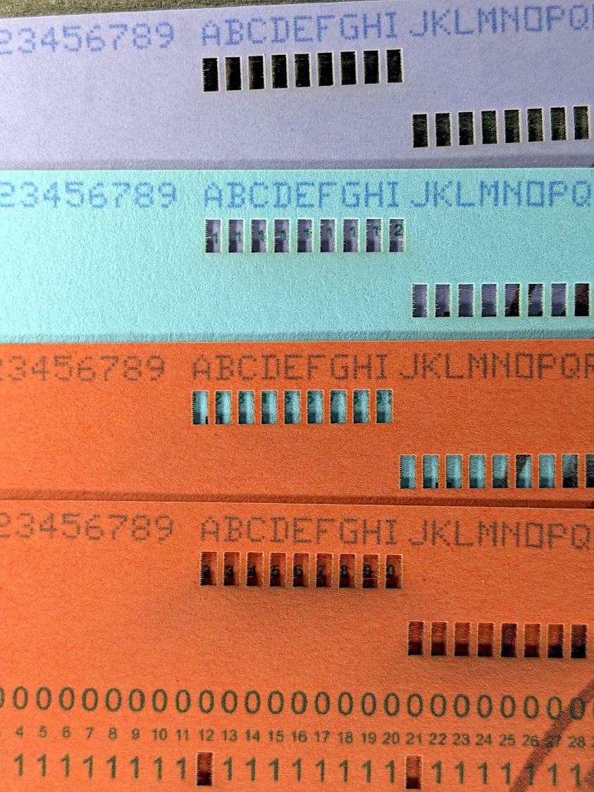
Using different card colors makes it easy to find your program deck in the Comp Center’s output bins:
Punched Cards – paper color vs smoke stains
The smoke stains on the bottom orange card came from the same LightBurn settings used with the purple (violet?) and blue (teal?) cards: 400 mm/s, 35% power, and assist air enabled.
The conventional wisdom is that you *do not* use assist air while engraving, to avoid pushing the smoke / soot down onto the material, and I’ve generally followed that rule. Apparently evaporating holes in the other colors doesn’t generate much smoke and I had no reason to notice the air was enabled.
The upper orange card differs from the lower one only in having the assist air turned off, so I have definitely learned my lesson!
Readers of long memory will recall the dual-path assist air setup that pushes 2 l/m through the nozzle when the LightBurn layer has AIR disabled, specifically to keep smoke out of the nozzle and away from the lens; that gentle breeze doesn’t push smoke into the paper.
FWIW, that’s why I run a set of test cards before I do anything fancy for the first time.
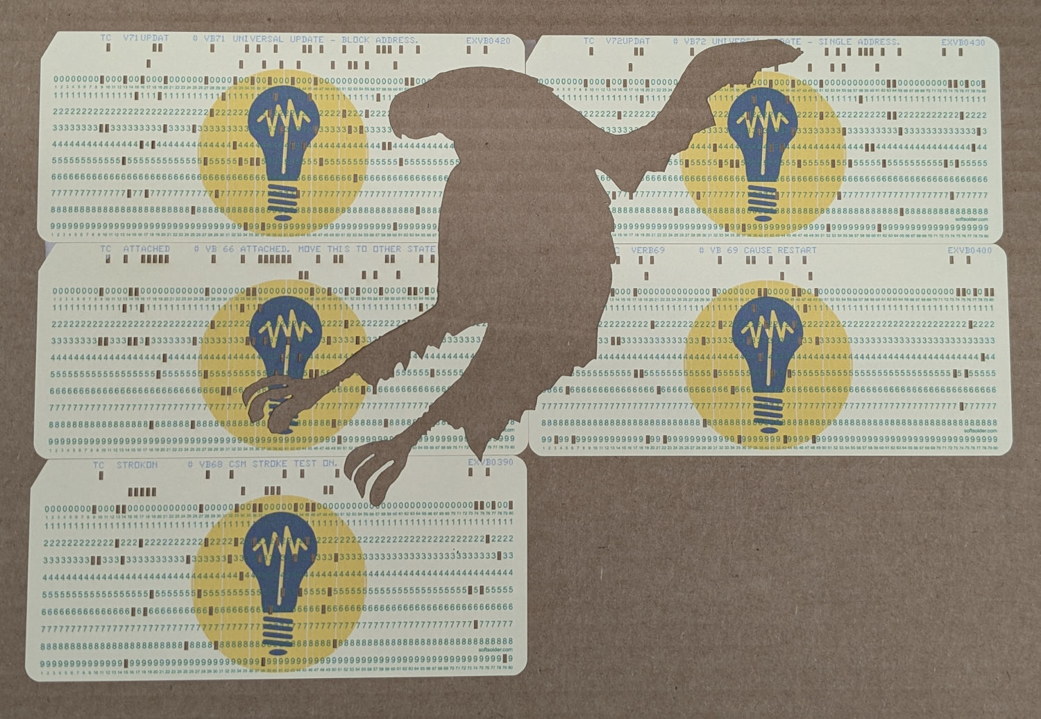
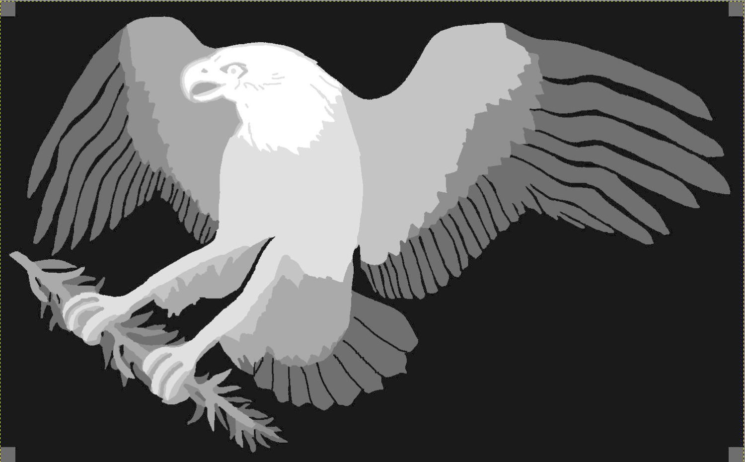
After considerable faffing, a few of the fifteen layers look like this in GIMP:
Apollo 11 Patch – eagle layers
Each layer is a connected white region defining the cut perimeter, which will expose some part of the layer(s) below it in the stack. The small squares in the corners provide a bounding box to make all the layers snap to the same location.
Put outlines on a cut layer, corner squares on a tool layer
Burn each layer separately
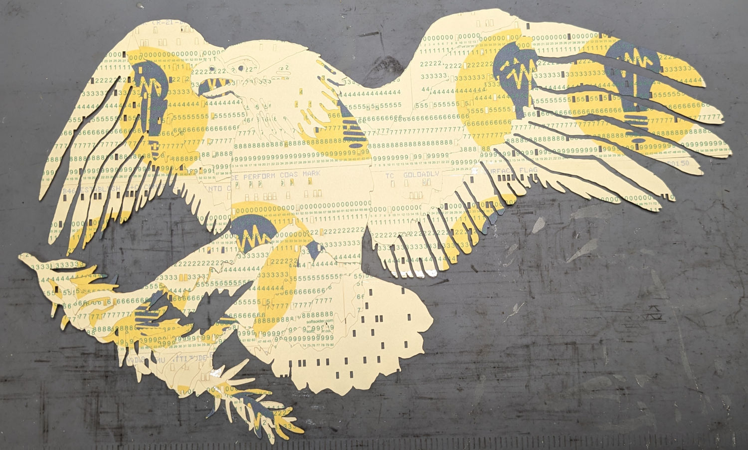
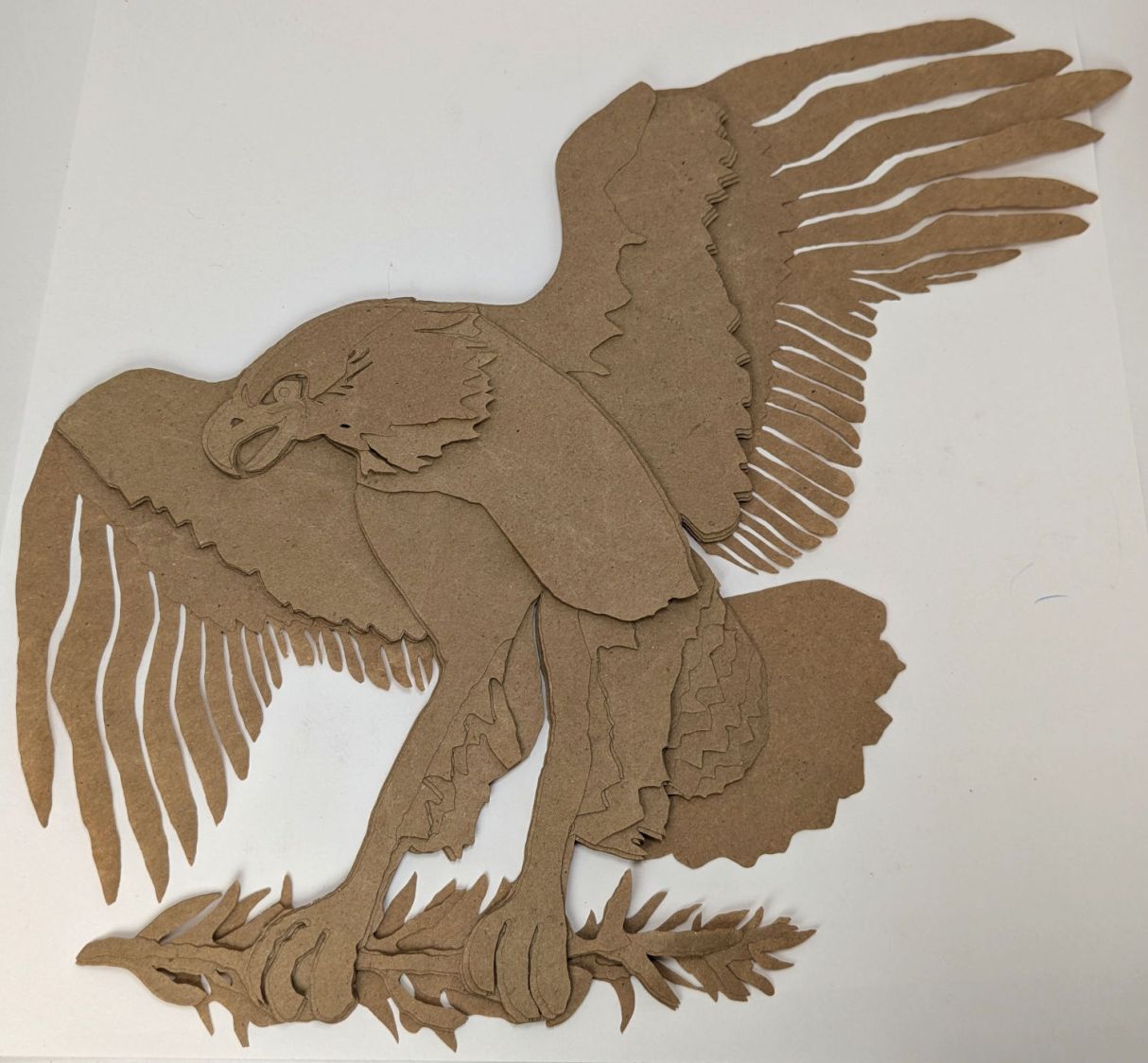
Testing the concept with packing paper looked surprisingly good:
Apollo 11 Eagle – layer test piece
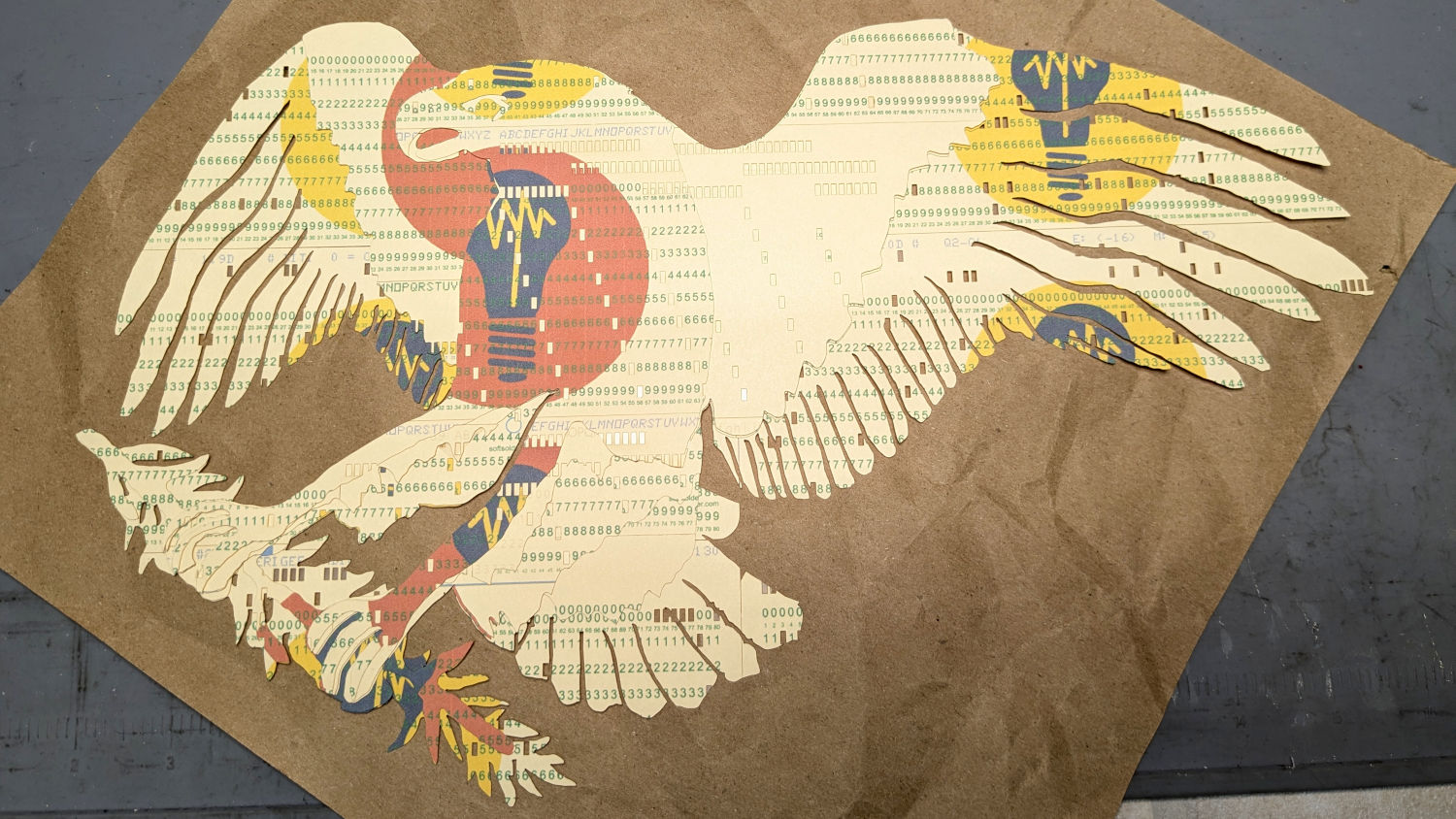
A few key layers on punched cards:
Apollo 11 Eagle – card partial test piece
The changes for each of those iterations required tweaking the original layer images to eliminate obvious-in-retrospect problems, recreating the SVG files, and importing into LightBurn. This is a relentlessly manual process.
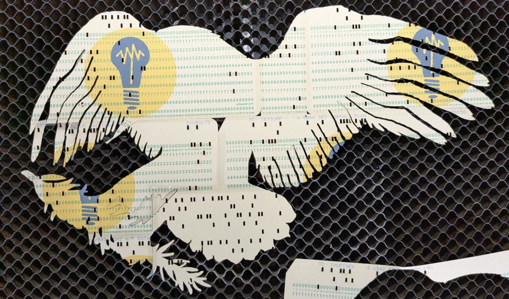
Then I ran a full-up test of all fifteen layers on cards punched with the Apollo source code.
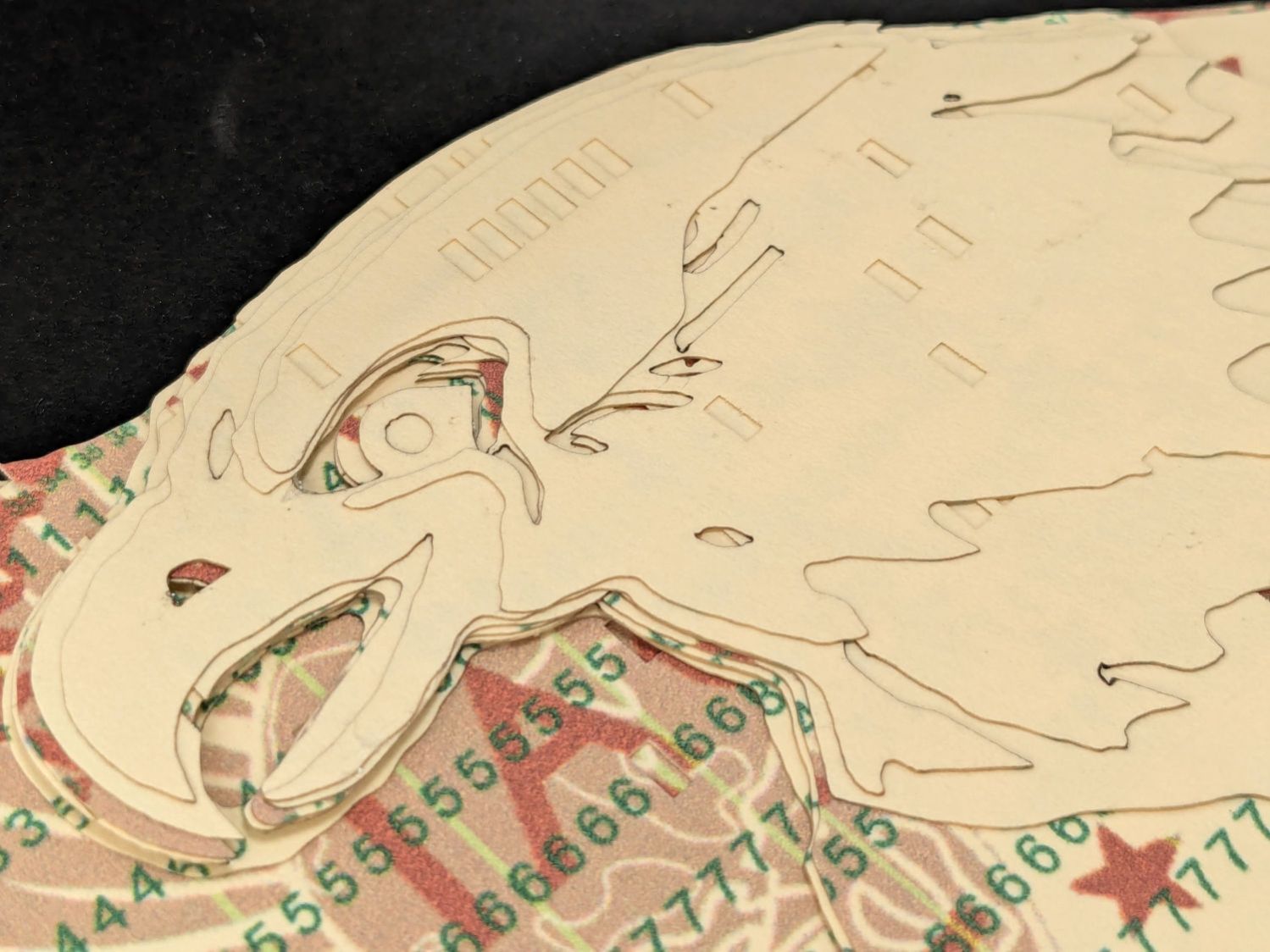
Cutting the head layers from face-down cards made them sufficiently white, although it’d be nice to have a different beak color and darker eyes :
Apollo 11 Eagle patch – layer test – head
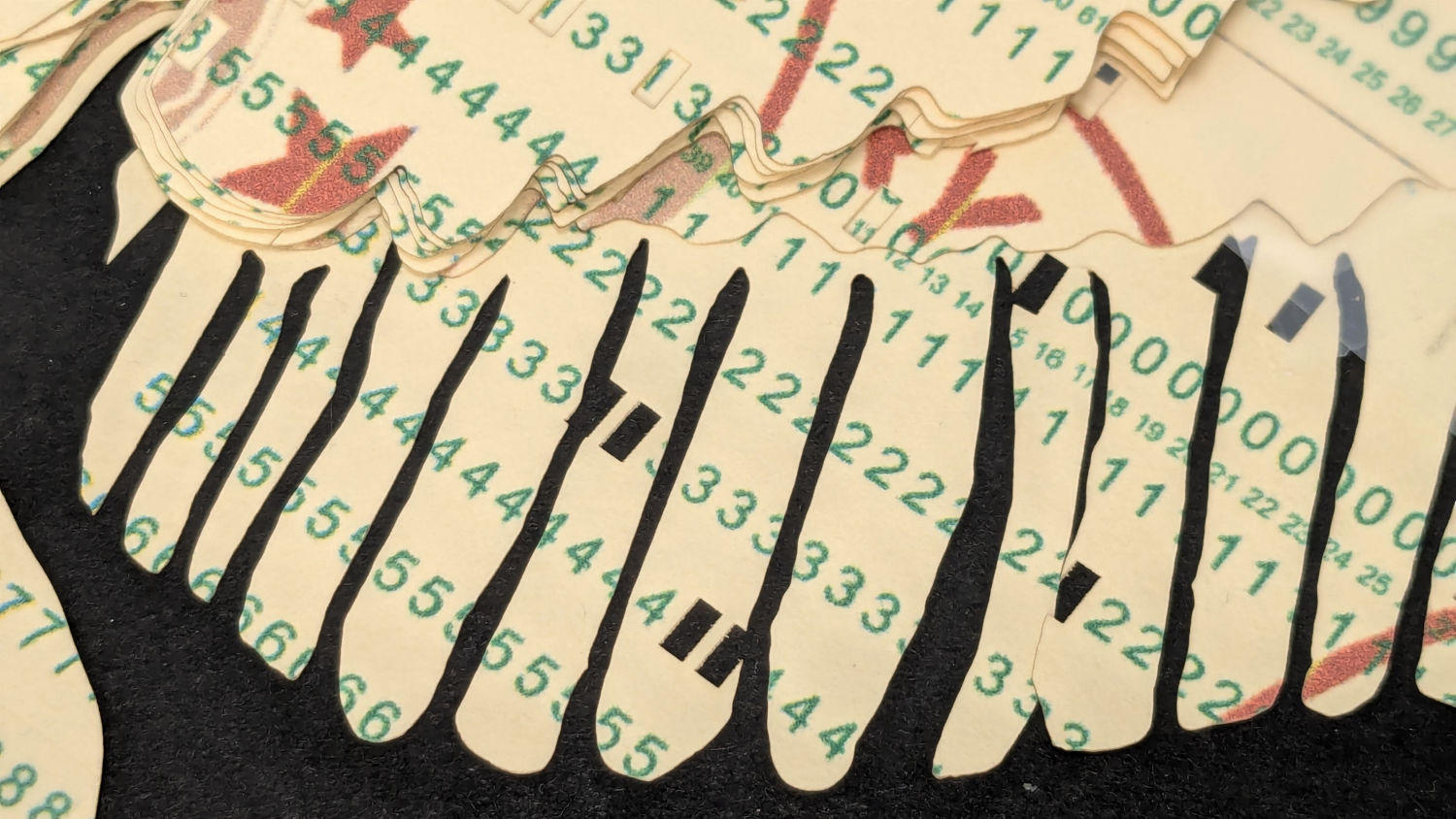
I must arrange the cards with text to put more holes in the wings, although too many will cause fragile feathers:
Apollo 11 Eagle patch – layer test – wing
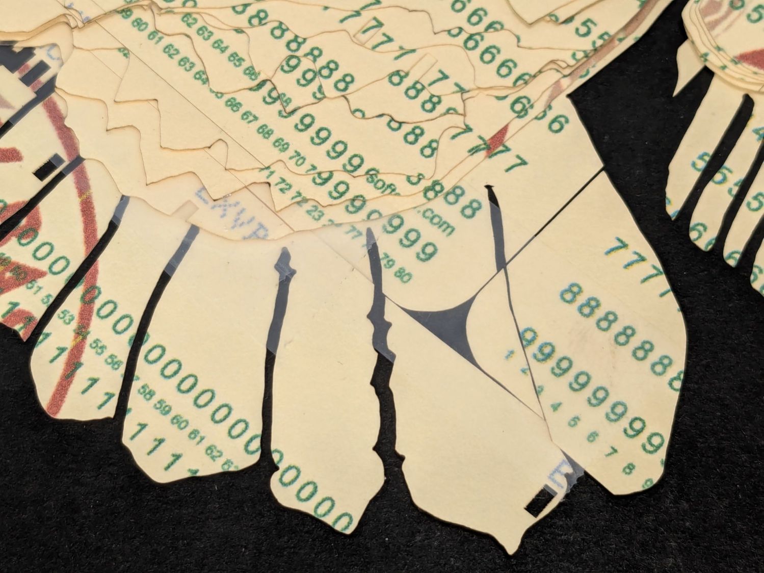
The white tail should be also done with face-down cards, more holes, and the three-way joint between the cards shifted under the tail layers to its left:
Apollo 11 Eagle patch – layer test – tail
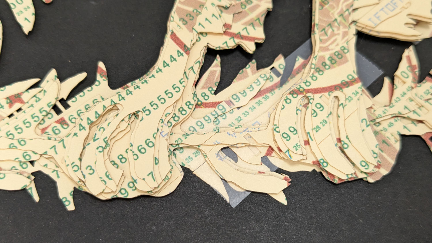
The feet and olive branch were a total faceplant, as successive layers did not register accurately enough to overlay the leaves:
Apollo 11 Eagle patch – layer test – feet
Not to mention those ug-u-lee claws.
The wing layers need more rounding along their edges, perhaps with some thin cuts to emphasize the feathers.


