Shortly after this season’s suet feeder deployment, the neighborhood raccoons emptied it. A few years ago, putting a 3D printed feeder at the end of a repurposed ski pole protected it for a few weeks, so I scrounged another pole from the pile, cut off the flattened top and battered tip, and put it into service:

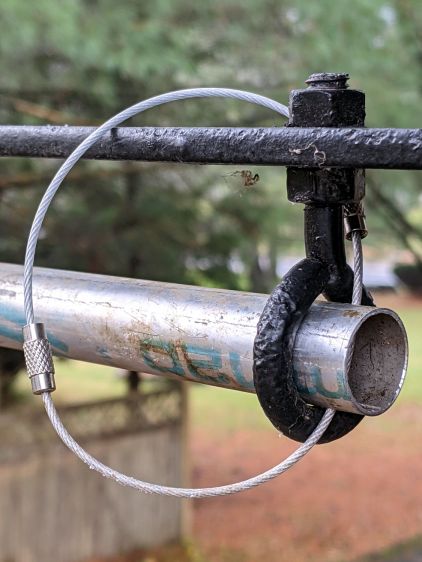
The near end has a loop made from a pair of stainless steel key cables, because a single cable was just slightly too short:
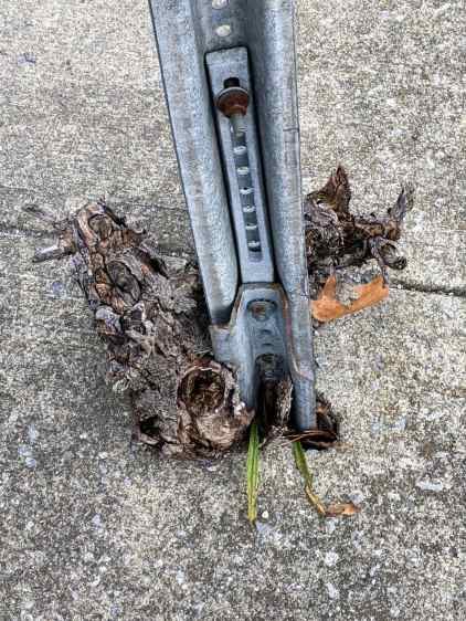
The far end has what was once a hook, beaten straight to fit through the hole, then beaten around the curve of the pole:

Raccoons lacking opposable thumbs, this should suffice until the black bear(s) spotted around here take up residence in the yard.