Ed Nisley's Blog: Shop notes, electronics, firmware, machinery, 3D printing, laser cuttery, and curiosities. Contents: 100% human thinking, 0% AI slop.
Tag: Improvements
Making the world a better place, one piece at a time
The ancient and much–repaired Sears humidifier works better in its new location across the living room with its front raised a few millimeters, which may have something to do with its plastic housing supporting a pair of heavy water containers for a few decades.
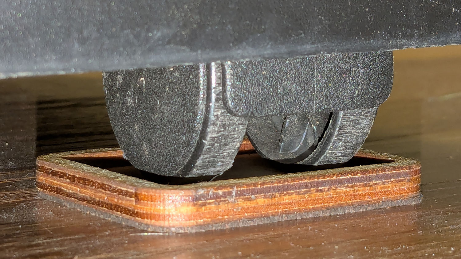
After fiddling around with shims to find the proper height, these feet descended from the Husky workbench feet:
Humidifier Caster Feet – installed
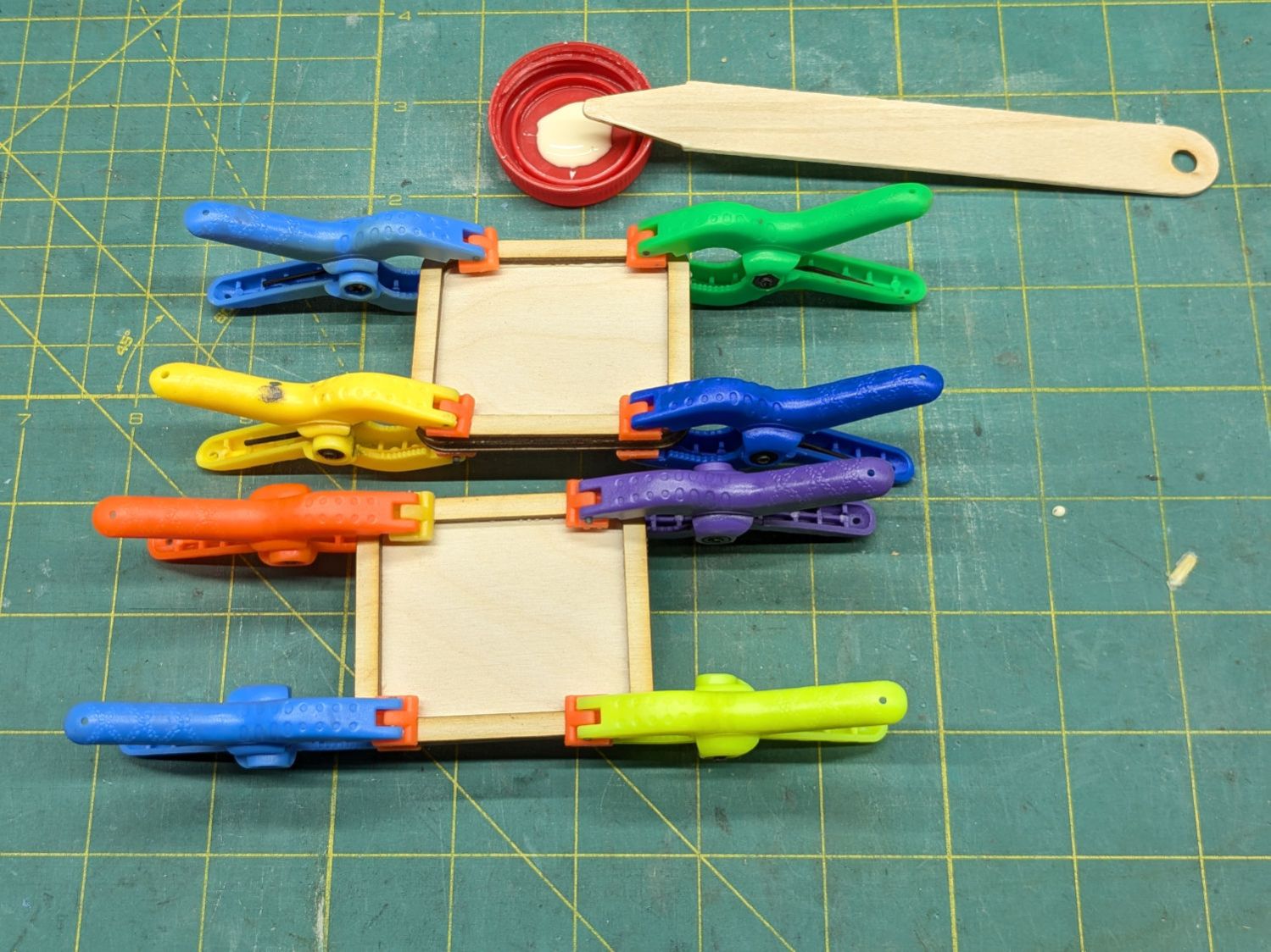
They’re glued up from 3 mm plywood sitting on a 1 mm layer of cork:
Humidifier Caster Feet – clamping
The humidifier seems much happier with its casters 4 mm above the floor. Seems awfully fussy to me, but there’s no arguing with success.
It turns out that keeping the garage door remote clipped to the starboard underseat pack on my Tour Easy attenuated its RF enough that even the directed receiver antenna couldn’t grab enough signal until I rolled onto the end of the driveway.
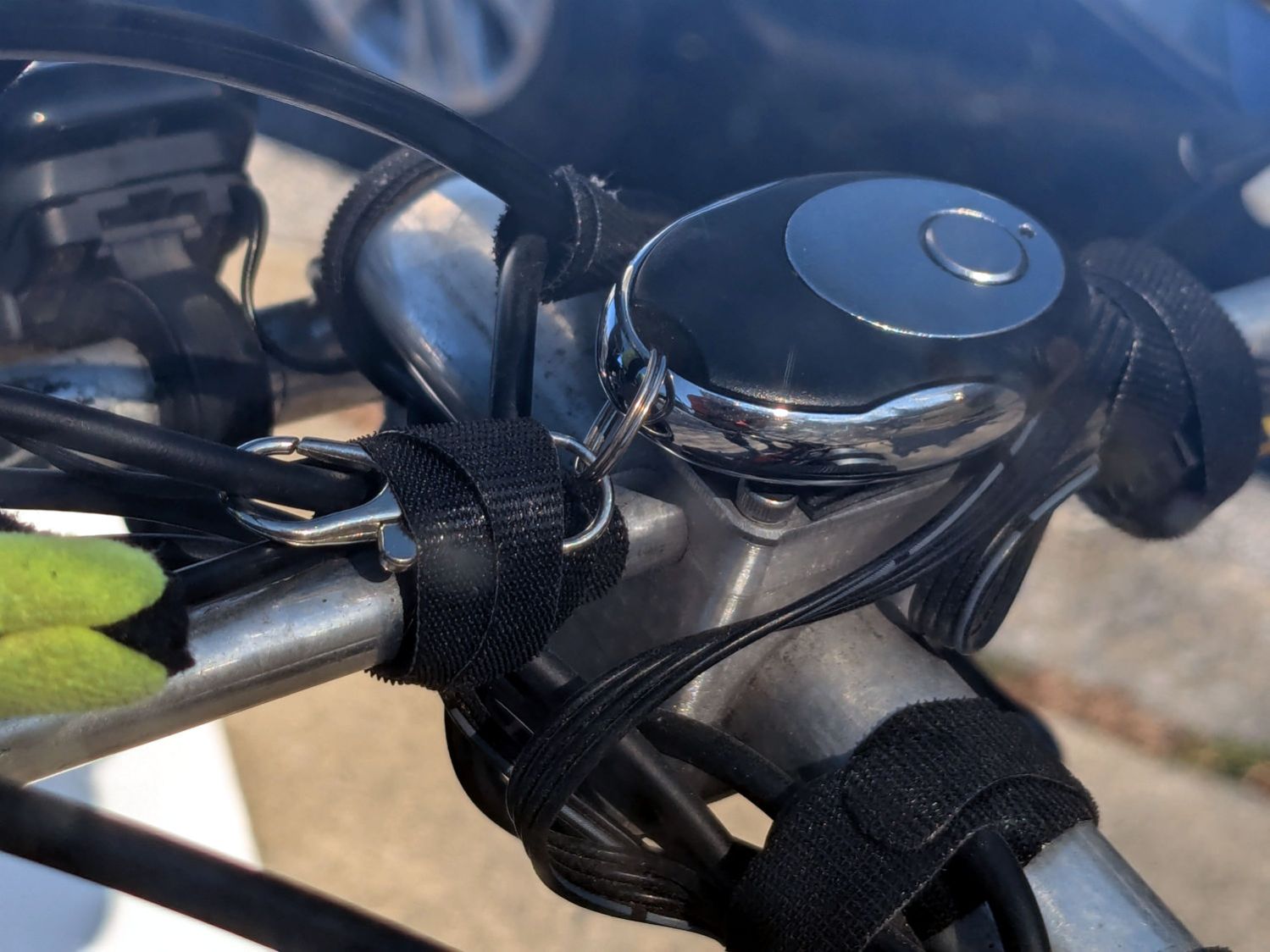
While contemplating what’s involved in making a 3D model of the remote’s curved backside, I realized the bike already had a perfect spot:
Tour Easy Zzipper Fairing – block mount
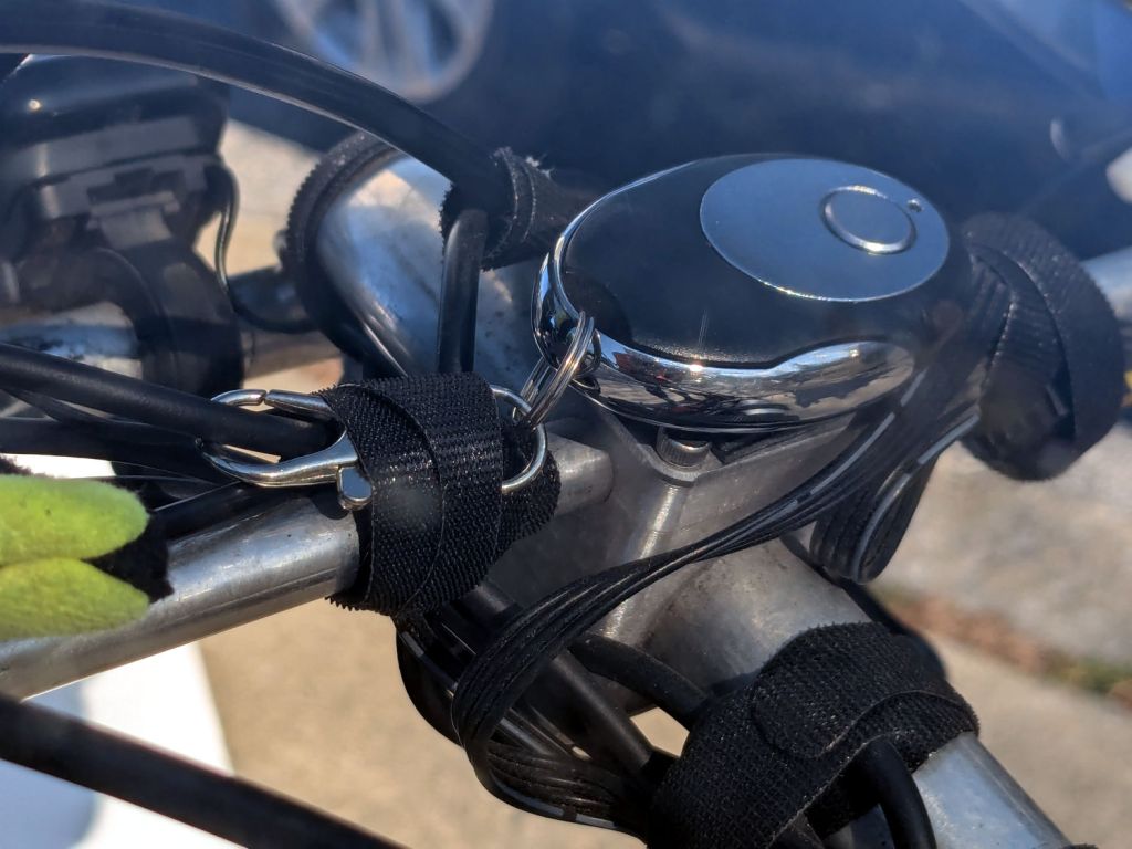
A few strips of good outdoor-rated foam tape later:
Tour Easy – garage door opener mount
Believe it or not, the camera is looking through the year-old and unwashed fairing on my bike.
Stipulated: aligning the PCB antenna flat against a small aluminum plate atop a bunch of aluminum bars isn’t perfect. However, enough RF wriggles out to trigger our opener from four houses down the hill, giving it plenty of time to haul the door out of my way.
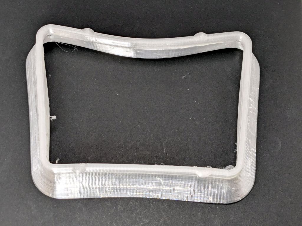
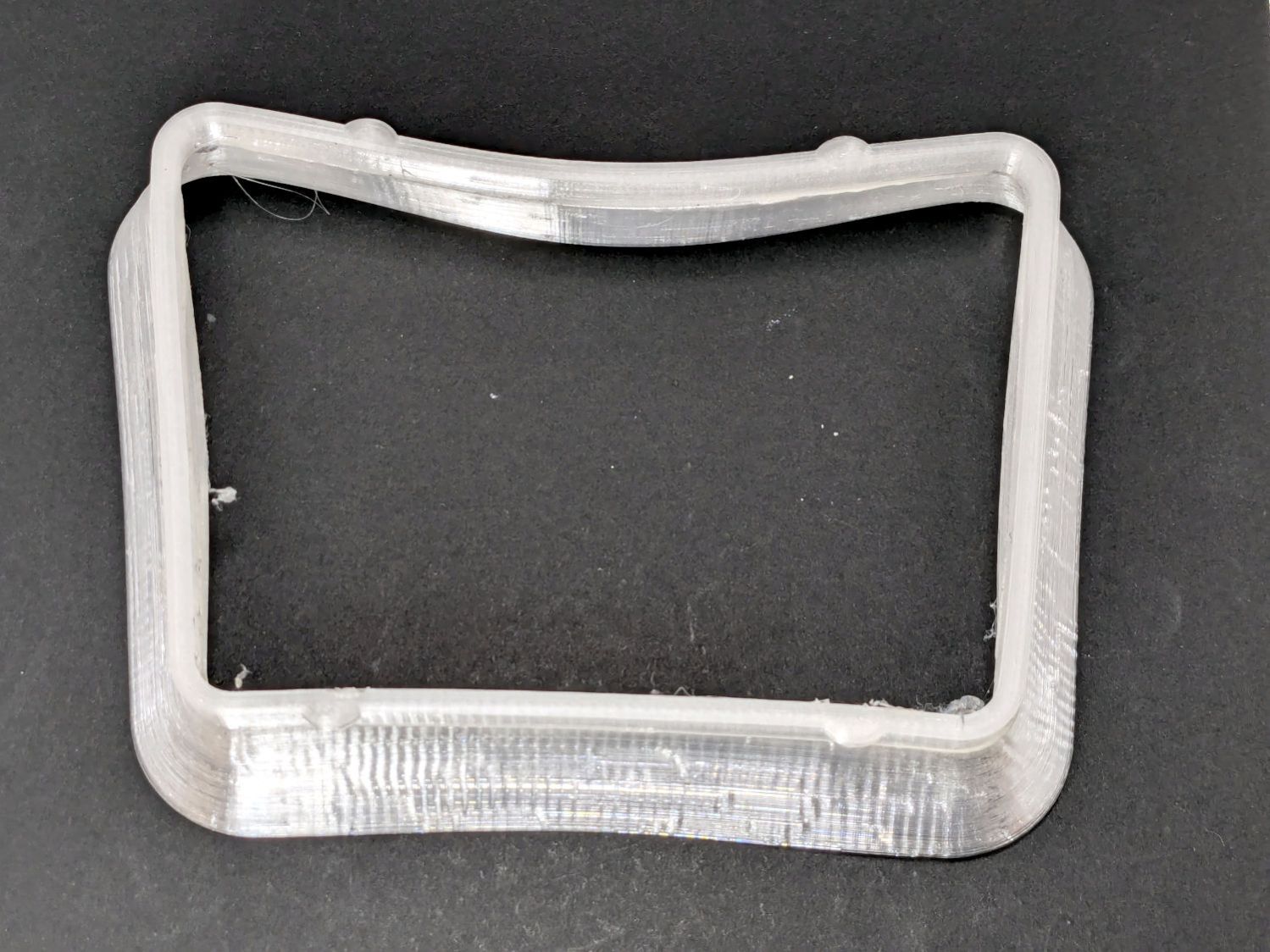
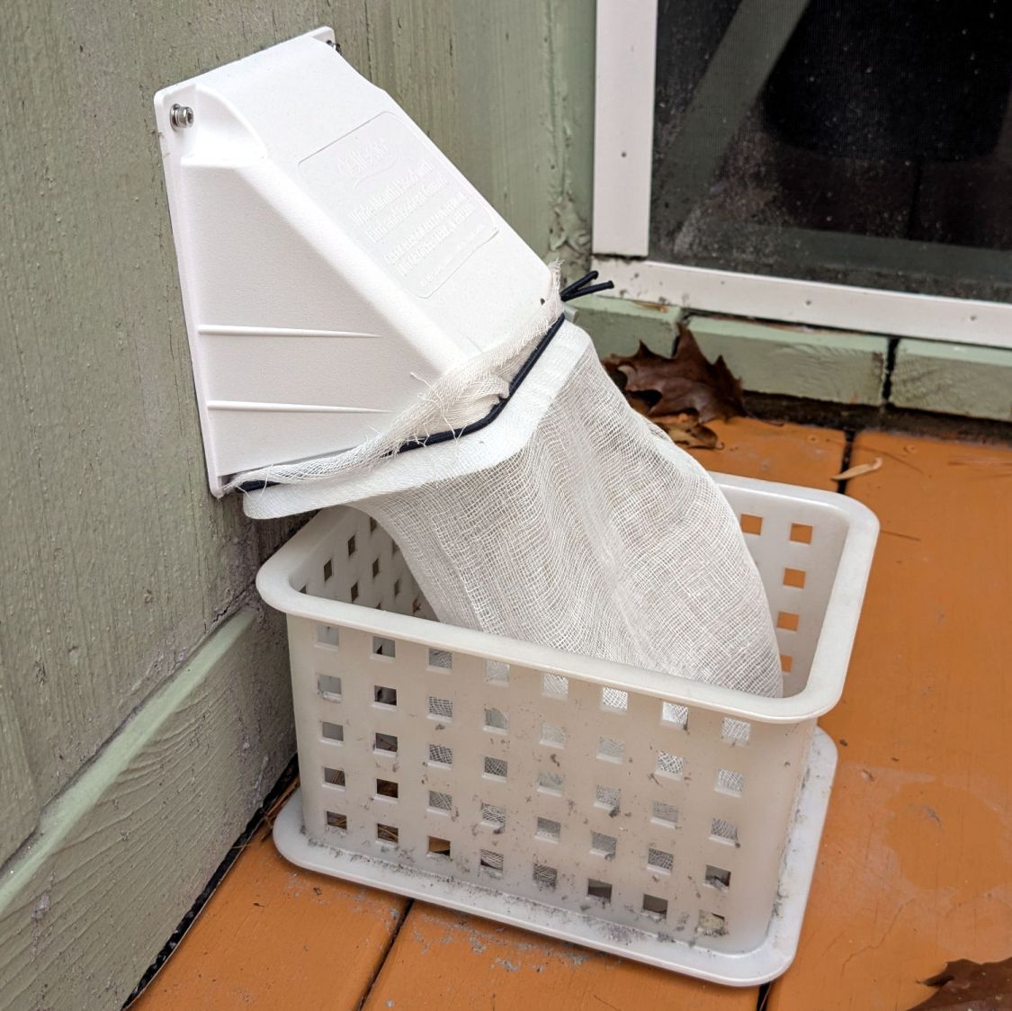
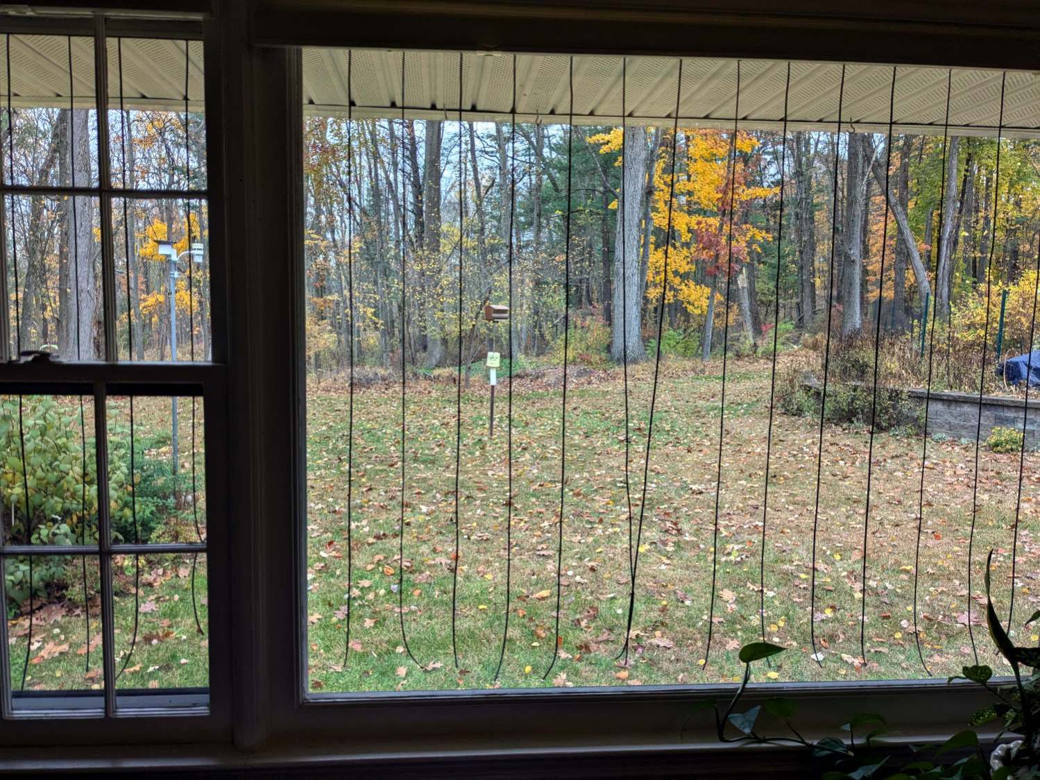
Mary counts birds for Project Feederwatch and the feeder goes up at Halloween, whereupon birds begin smashing against the windows. Having bought a lifetime supply of paracord for this purpose on our previous house, I made a DIY Birdsaver for the rear windows:
DIY Birdsavers – interior view
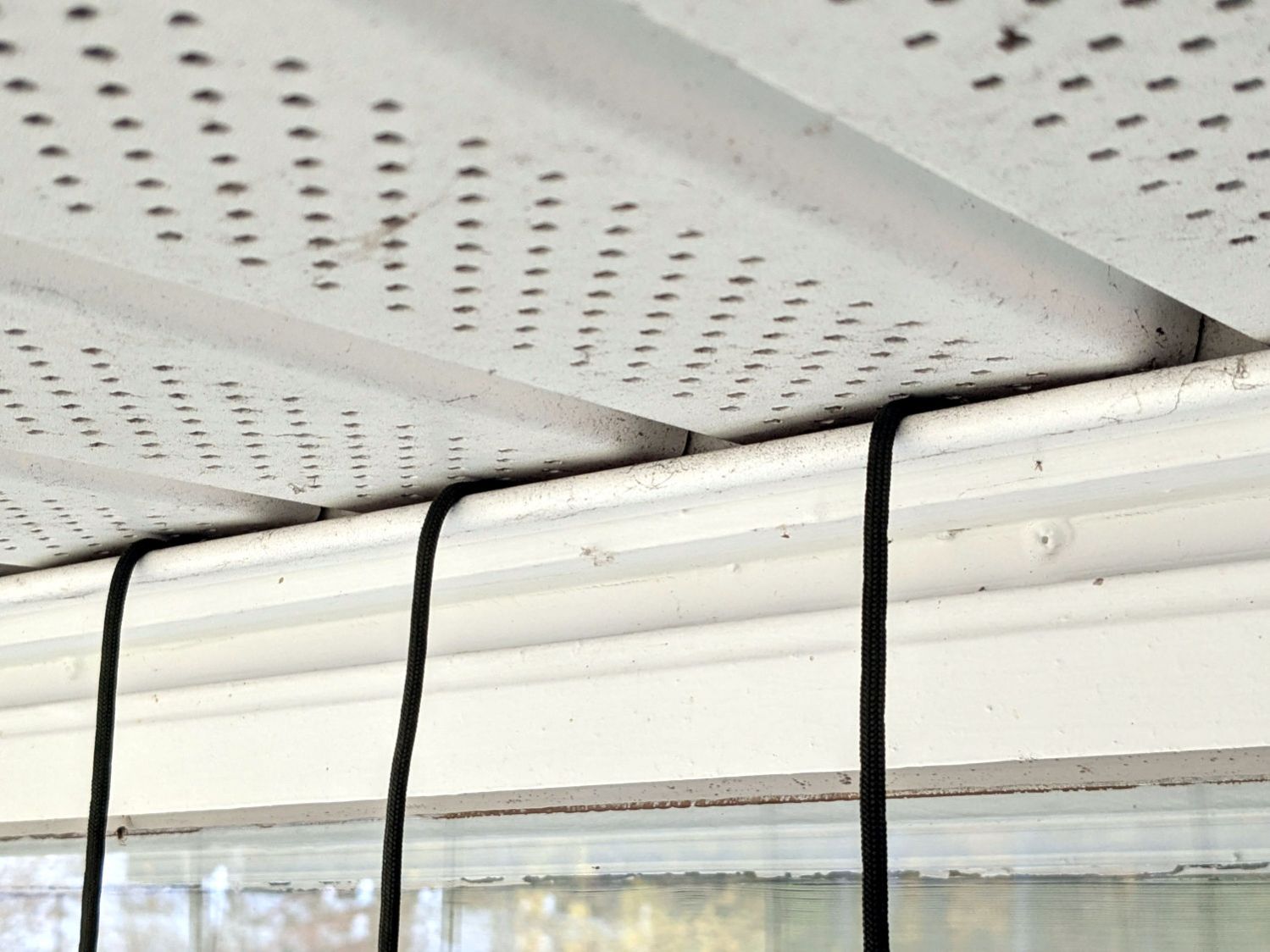
This project was tremendously simplified by discovering the soffits consist of molded PVC sheets having exactly the proper 4 inch spacing and a convenient lip perfectly suited to capture the knot:
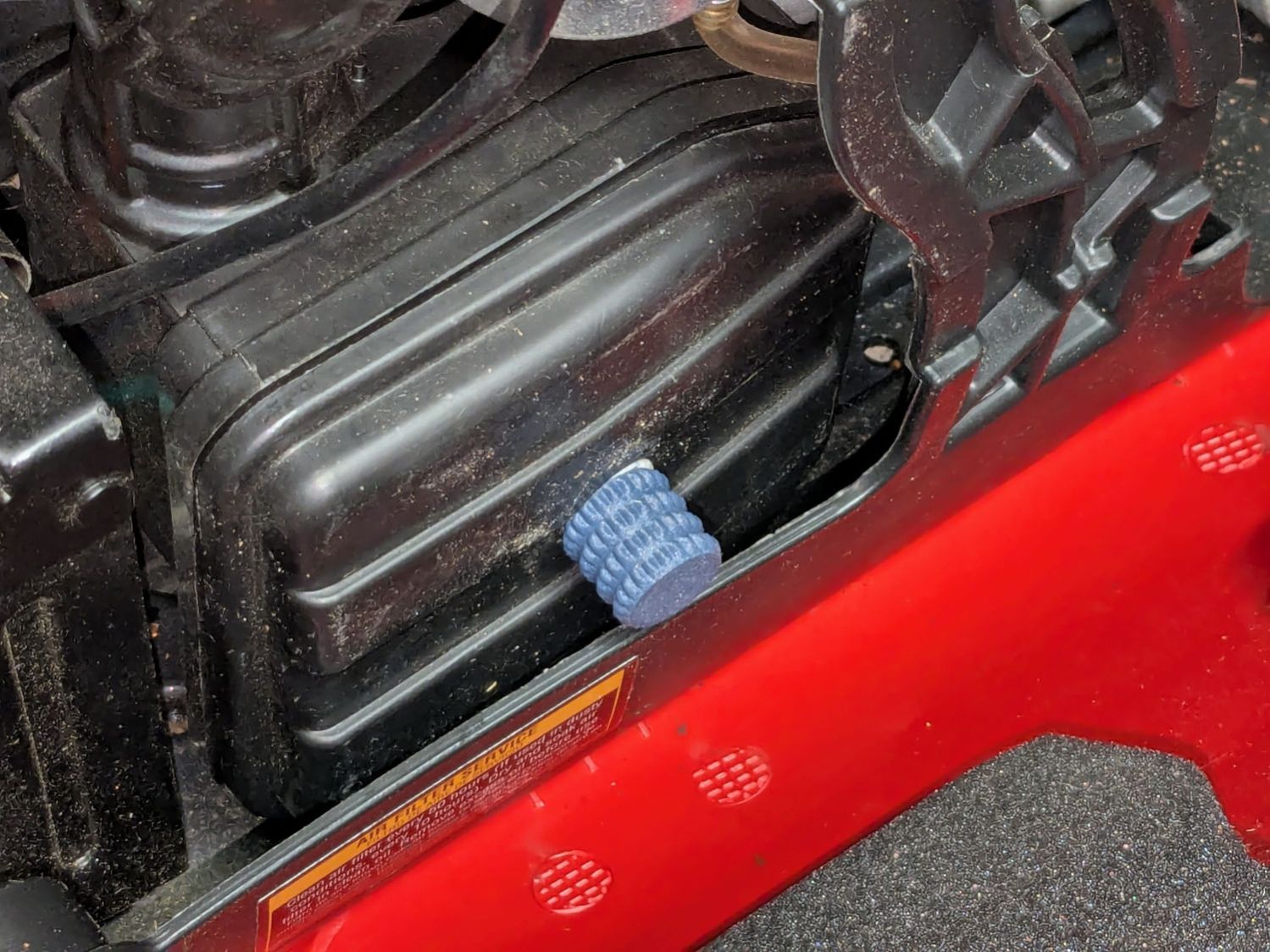
Part of the Autumn festivities around here involves blowing leaves into piles, then shredding them into garden mulch. Given that I have a plug-in electric leaf blower / wind stick, I use this as an excuse to exercise the emergency generator (similar to that one) with a (relatively) short extension cord.
As with all small gasoline engines, I fire a shot of starting fluid into the air cleaner to reduce the number of engine-start yanks, which means I must remove the generator’s side panel and unscrew the filter cover. For years I have sworn mighty oaths on the bones of my ancestors to knobify that screw, thus eliminating fiddling with a screwdriver.
Mary’s zero-mph crash loosened the starboard handlebar plug enough to let it eventually decamp for parts unknown. Its replacement, a somewhat fancier aluminum plug with an expanding cone retainer using an actual M3 nut, worked fine for the last year, but Mary recently noticed the socket head screw had worked loose.
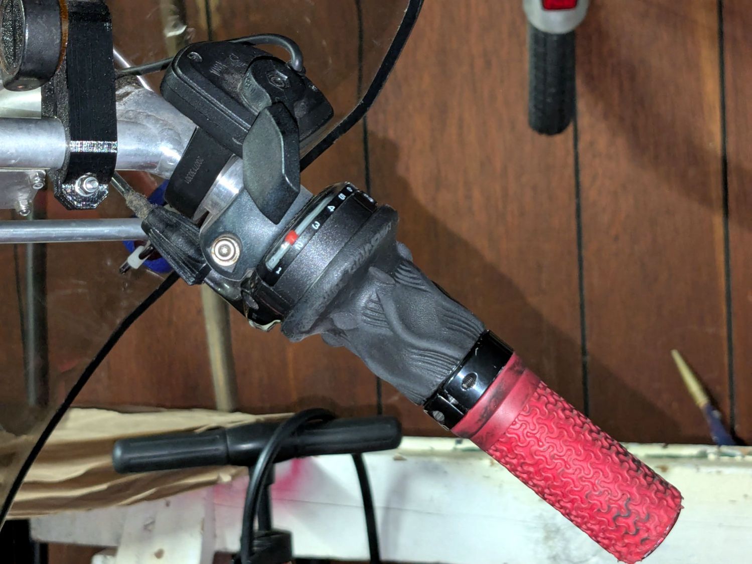
In the interim, I’d moved the Bafang thumb control from its original position on the crossbar to just above the rear shifter:
Tour Easy – right handlebar control stack
Which moved the clamp on the shortened grip off the end of the handlebar tube, so I flipped the grip around, tightened the clamp, and installed the plug.
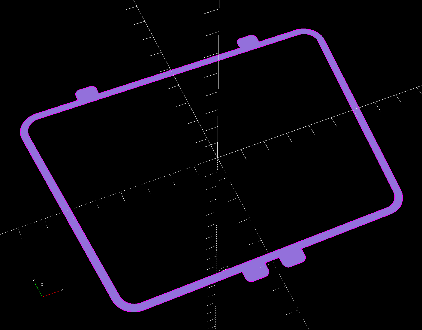
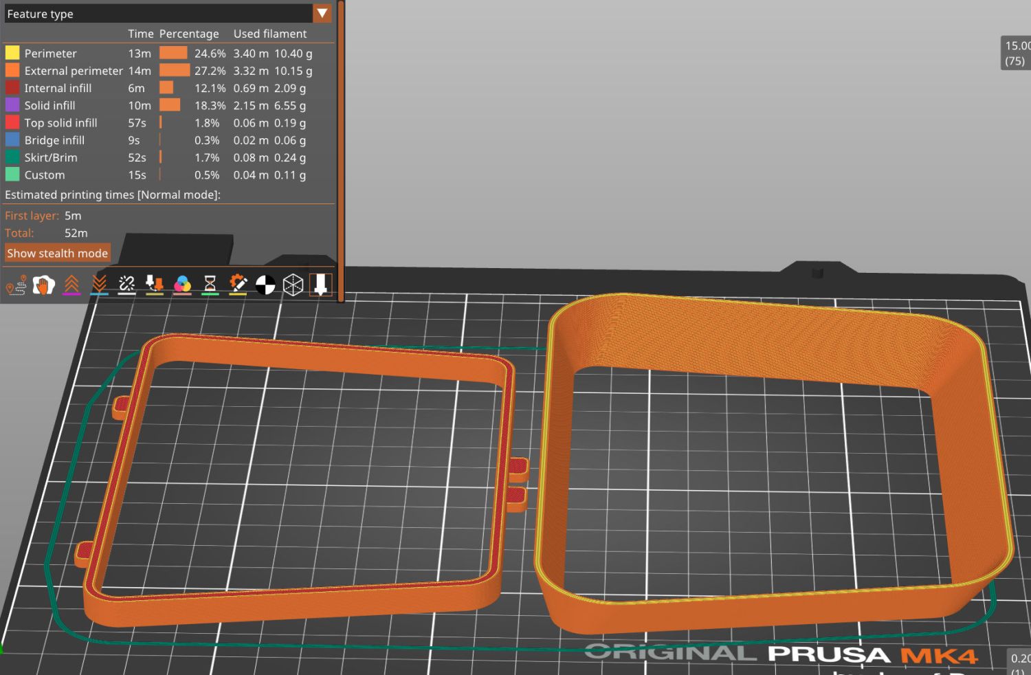
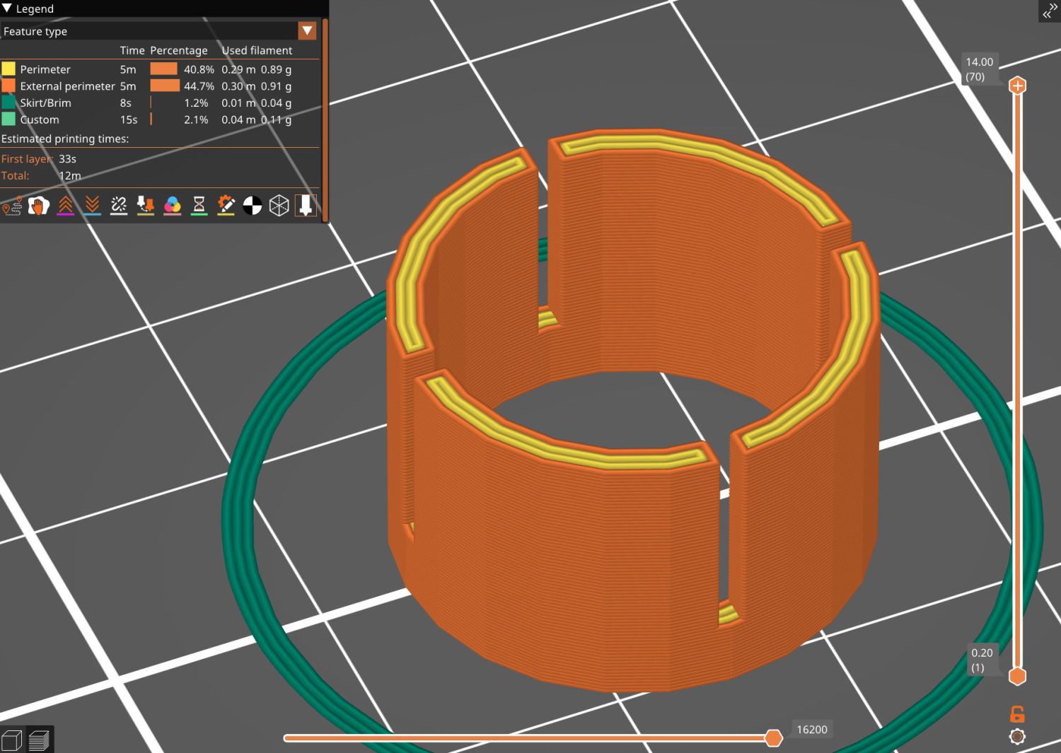
Unfortunately, the grip ID is 4 mm larger than the tube ID, which meant the plug’s cone retainer was struggling to hold on in there. Perhaps the plastic cone has relaxed bit, but I figured giving it more traction would be a Good Idea™ before I declared victory:
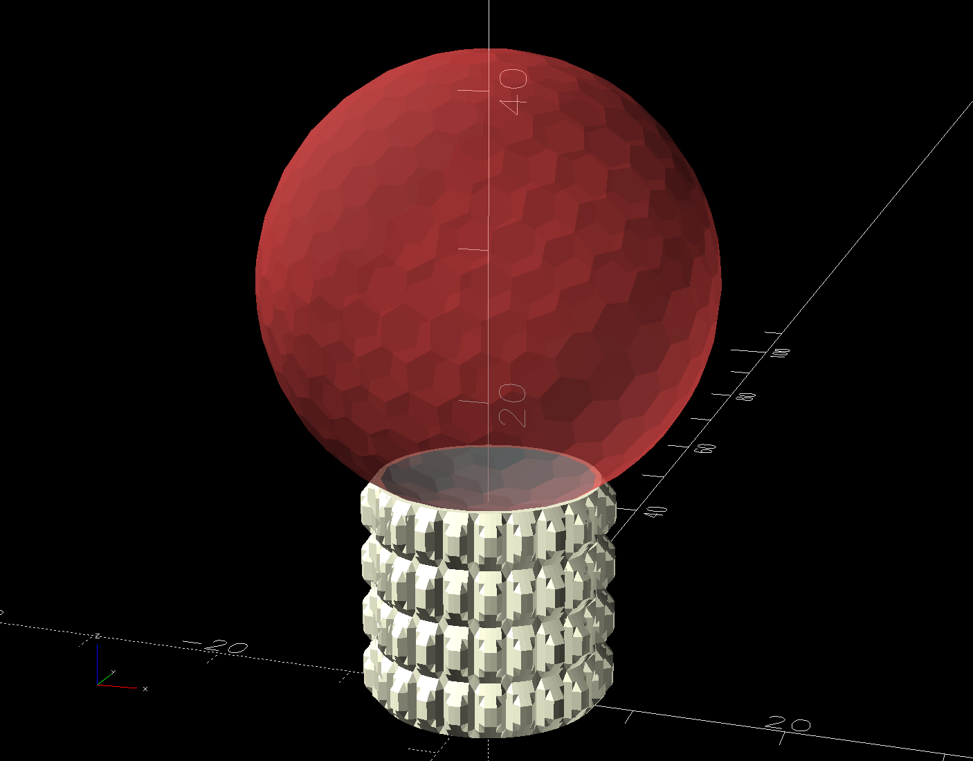
Handlebar Grip Sleeve – PrusaSlicer
It’s a little plastic sleeve with slots to let it expand against the inside of the grip:
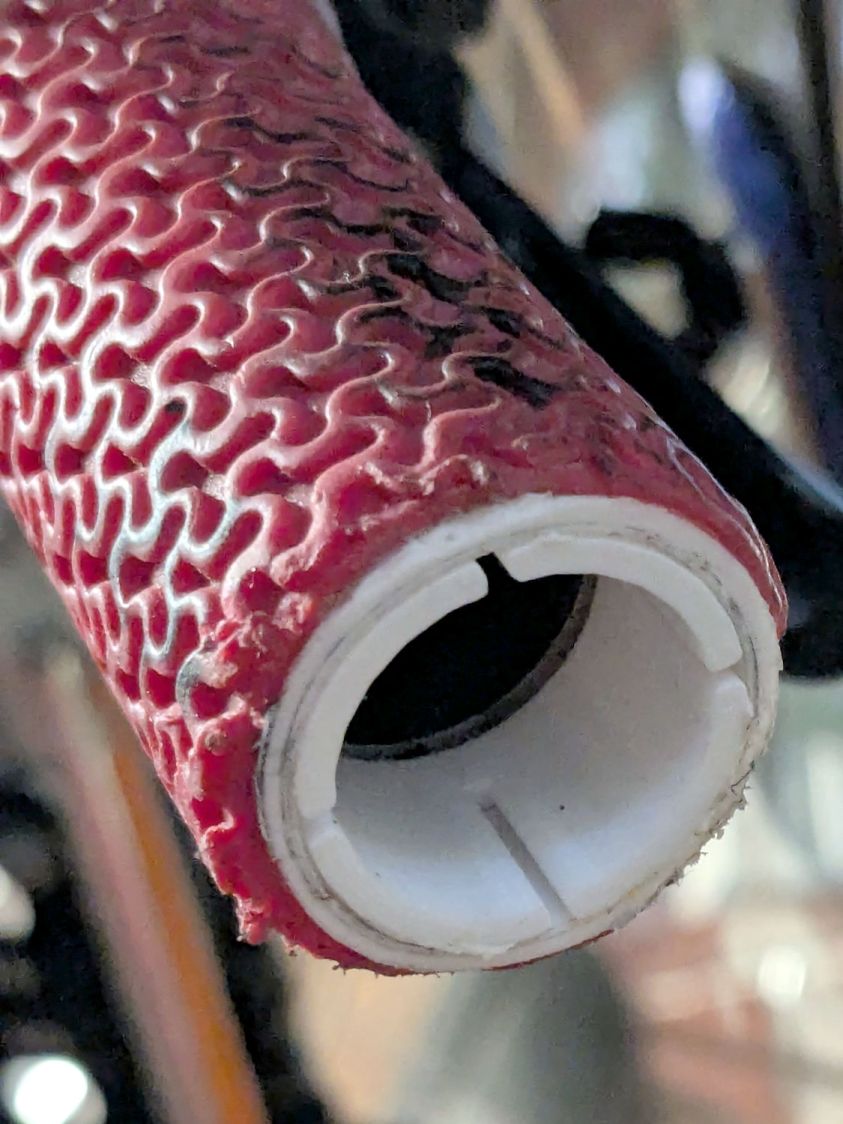
Handlebar grip sleeve – installed
Yes, it’s sticking out slightly; you can see the corresponding gap up inside next to the tube.
A wrap of double-sided sticky tape glues it in place as the retainer presses it against the grip ID and a dot of low-strength Loctite should keep the screw from loosening again.
The OpenSCAD source code:
// Handlebar grip sleeve
// Ed Nisley - KE4ZNU
// 2025-10-25

include <BOSL2/std.scad>

/* [Hidden] */

ID = 0;
OD = 1;
LENGTH = 2;

HoleWindage = 0.2;
Protrusion = 0.1;
NumSides = 3*2*4;

$fn=NumSides;

Sleeve = [18.5,22.0,14.0];
Kerf = 1.0;

  difference() {
    tube(Sleeve[LENGTH],id=Sleeve[ID],od=Sleeve[OD],anchor=BOTTOM);
    for (a=[0,90])
      zrot(a)
        up(Sleeve[LENGTH]/4)
          cuboid([2*Sleeve[OD],Kerf,Sleeve[LENGTH]],anchor=BOTTOM);
  }
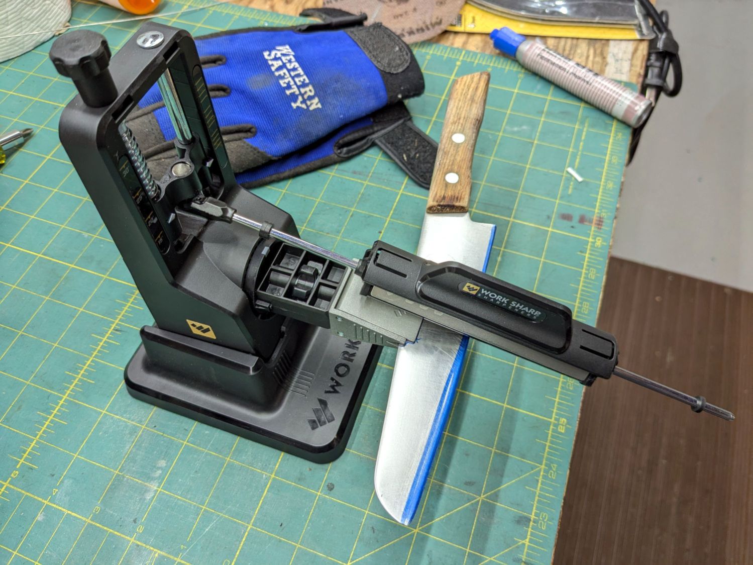
Protip: Wear gloves, because you’re working in front of an unprotected and eventually very sharp blade.
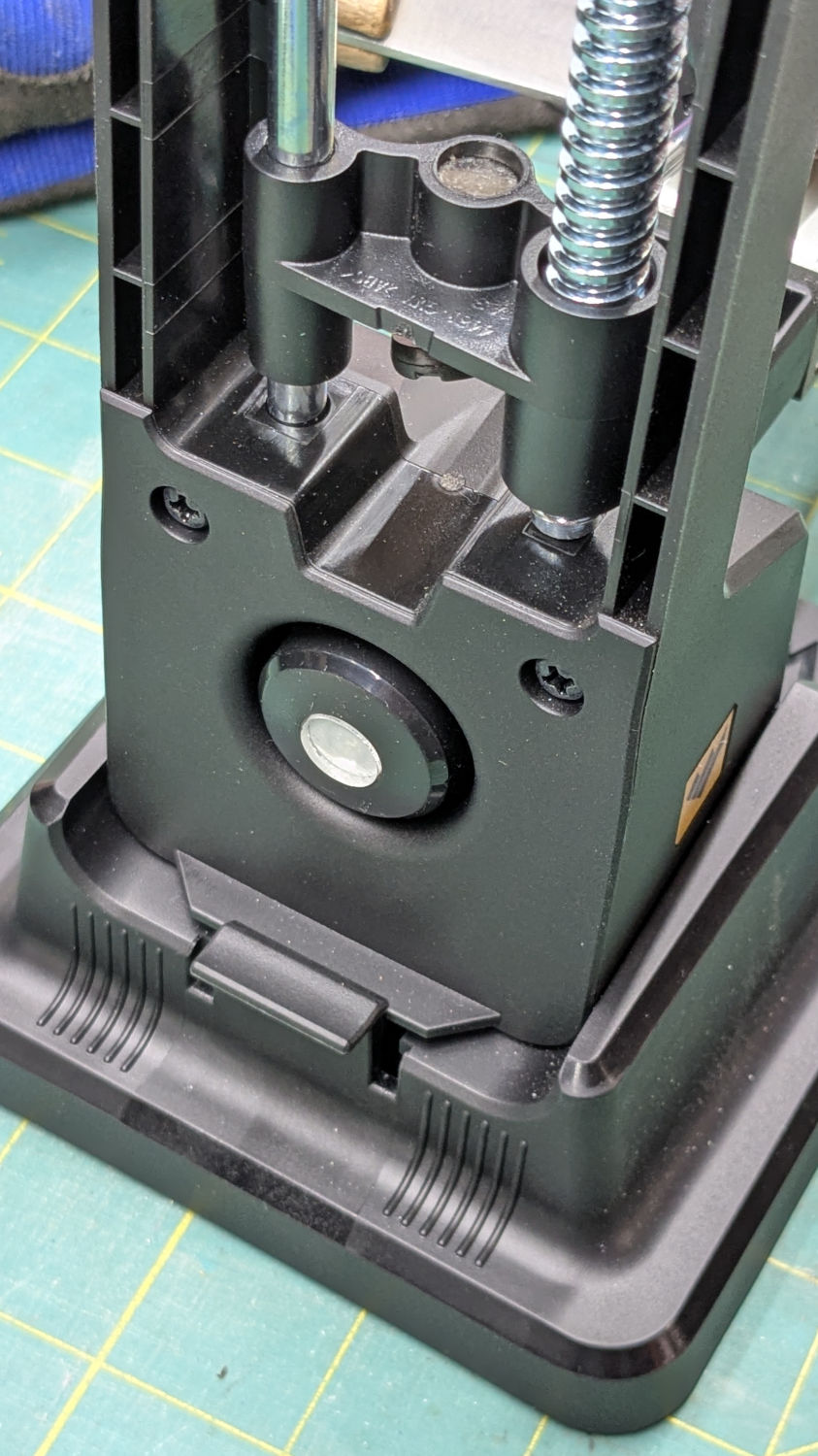
The blade-holding clamp snaps magnetically into a rotating chuck so you can flip the knife over, at least if it’s not quite as long as that one. The chuck index has a spring-loaded release button:
Work Sharp Knife Sharpener – rear view
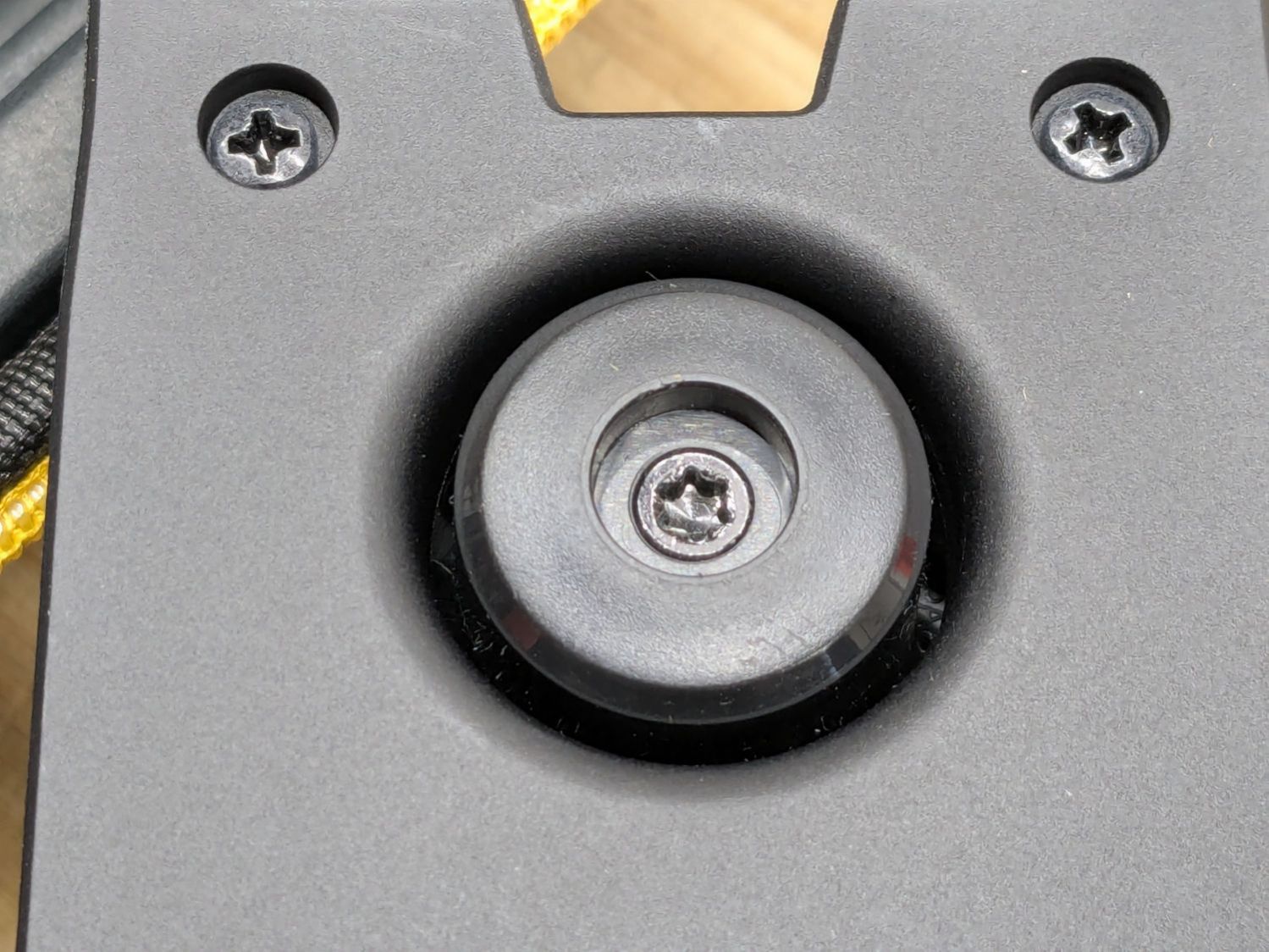
The spring is powerful and the button arrived with a recess around the screw holding the chuck together:
Work Sharp Knife Sharpener clamp button – as received
Pressing the button hard enough to release the chuck hurt my index finger, but their Tech Support said it’s like that and that’s the way it is. Turning the screw adjusts the spring compression, but I think this situation calls for “more secure” rather than “easy to push”.
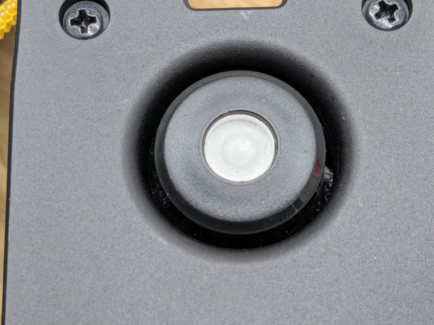
Fortunately, I have a laser cutter and know how to use it:
Work Sharp Knife Sharpener clamp button – filled
Despite appearances, it’s a 10 mm disk of 4.3 mm clear acrylic stuck to the screw head with a snippet of white double-sided tape and flush with the surrounding plastic surface.
A smooth button makes my index finger much happier …