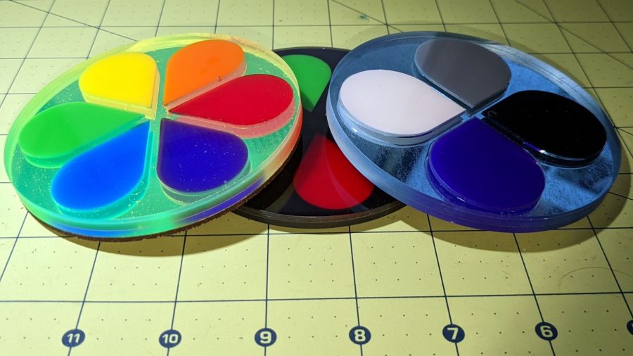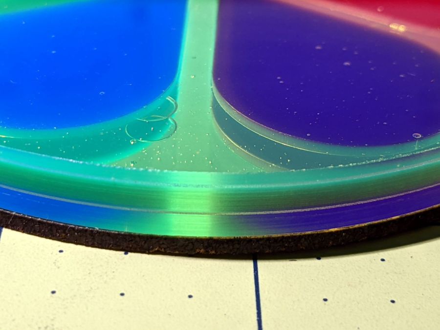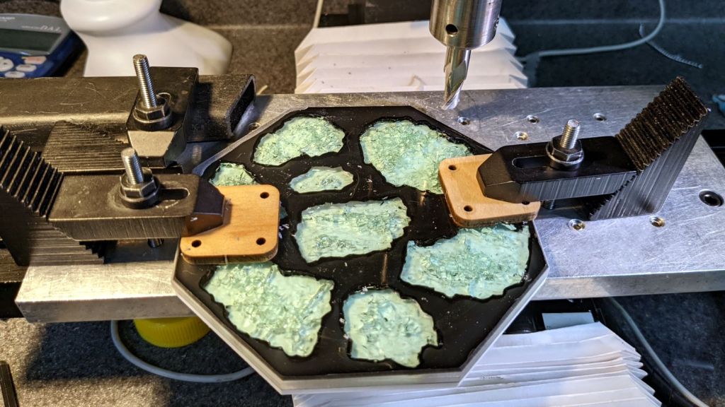
The kludge required to trim the coaster rims disturbed the silt enough to reveal a long-lost 5 inch 4 jaw chuck that fit neither the old South Bend lathe nor the new mini-lathe. In any event, the chuck does have an adapter plate on its backside, it’s just not the correct adapter plate for the spindle on my mini-lathe.
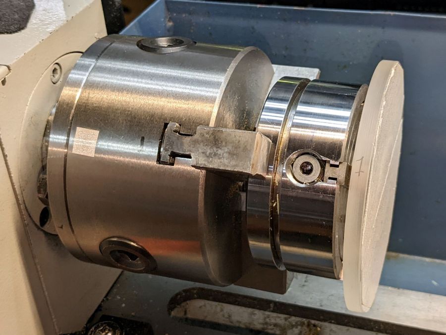
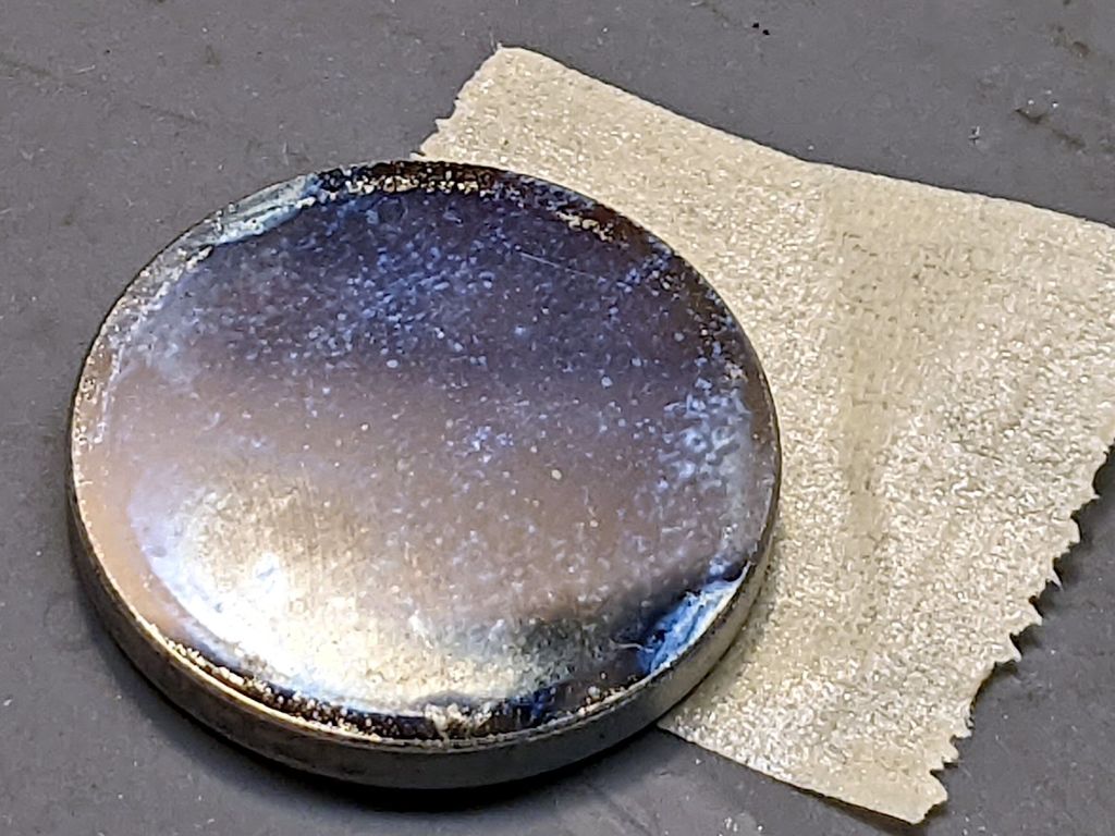
Making it fit required enlarging an existing recess to fit the spindle plate, a straightforward lathe job with the plate grabbed in the 3 jaw chuck’s outer jaws:

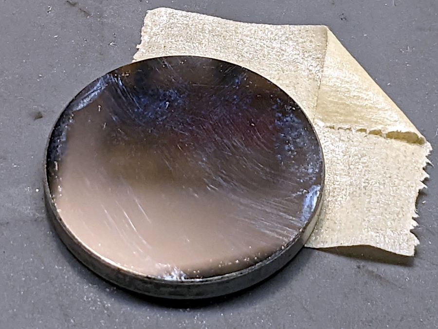
Carbide inserts don’t handle interrupted cuts very well, but sissy cuts saved the day. The plate is kinda-sorta cast iron, so the “chips” are dust and a vacuum snout reduces the mess; you can see some chips inside the bore.
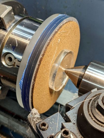
A faceplate for the mini-lathe lathe located three holes matching the spindle plate, after I noticed the amazing coincidence of both parts having 26 mm bores. Making an alignment tool from a scrap of 3/4 inch (!) Schedule 40 PVC pipe was an easy lathe job:

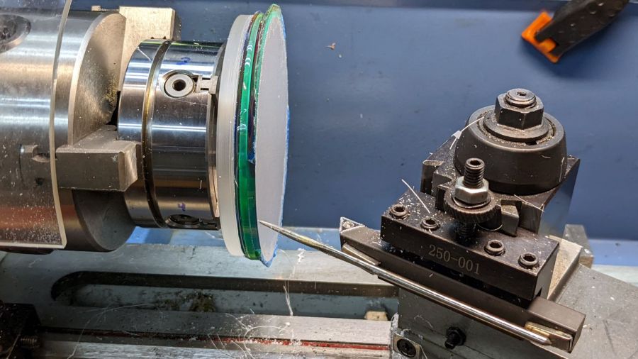
Transfer-punching those holes produced pips on the chuck side of the adapter plate:
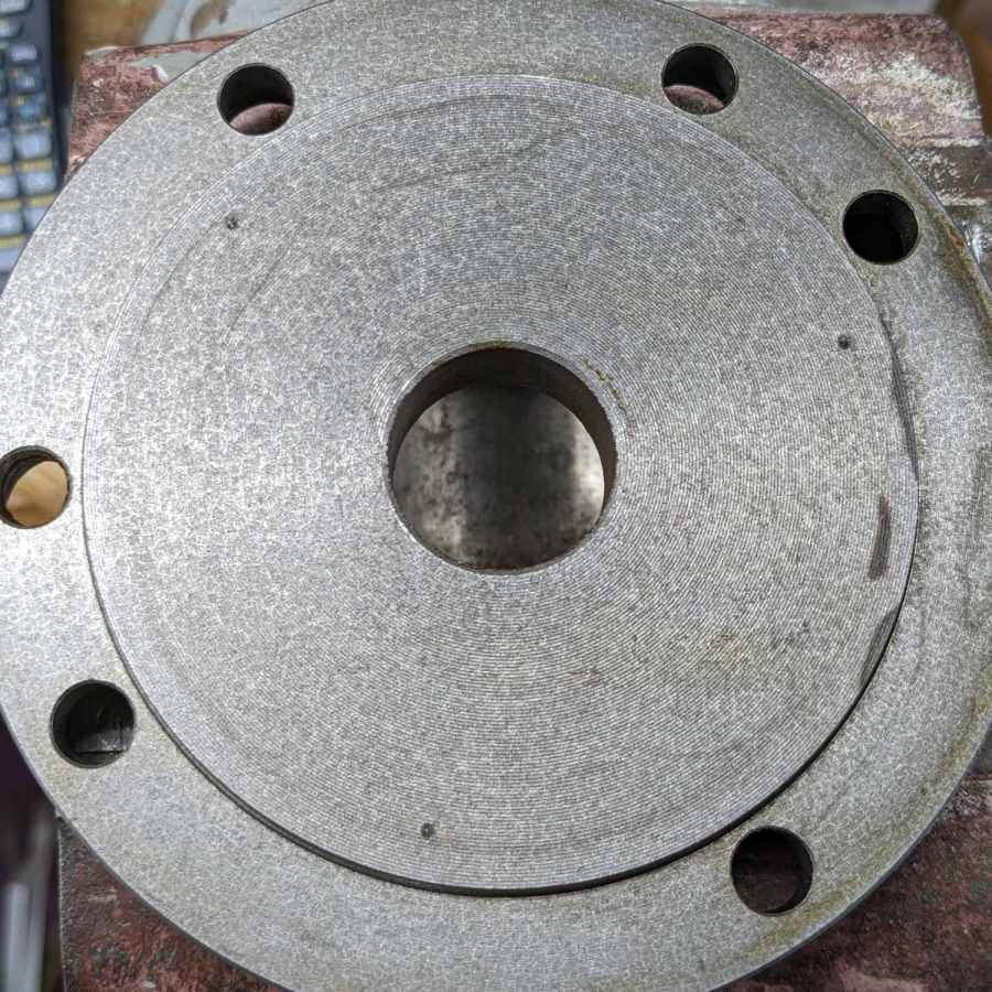
I thought about freehanding the holes, but came to my senses:
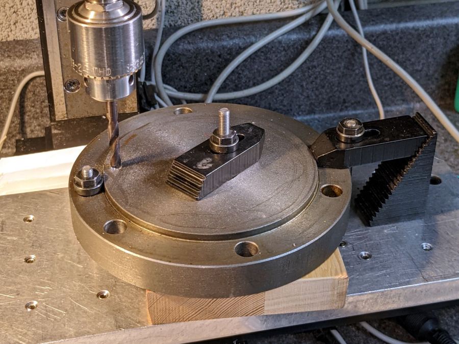
Of course, the Sherline lacks enough throat for the plate, so each hole required clamping / locating / center-drilling / drilling / finish drilling. With all three drilled, hand-tapping the threads was no big deal:

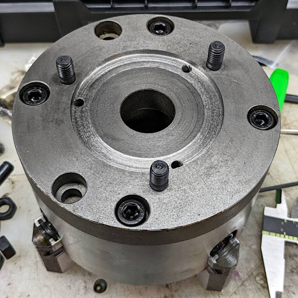
Those are M8×1.25 studs from LMS (although the ones I got look like the 30 mm version), with the long end sunk in the adapter plate to put the other end flush with the nut on the far side of the spindle plate:

And then it fits just like it grew there, although the jaws don’t have much clearance inside the interlock cover:
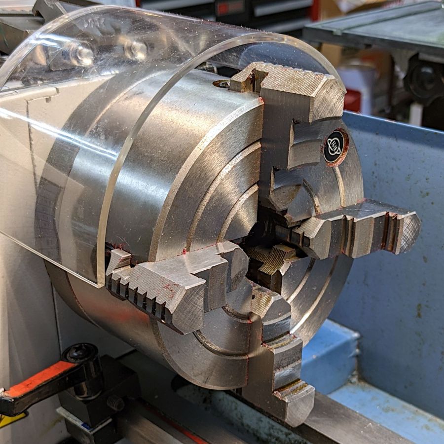
Now I’m ready for the next set of coasters and, if the jaws stick out too far, I can gimmick the interlock switch for the occasion.
If the truth be known, I ordered two sets of those studs along with the 4 inch 4 jaw chuck intended for the mini-lathe, so, if anything, I’m now over-prepared.
The description of the 4 inch chuck seems inconsistent with its listed dimensions, which may be why I ended up with the larger chuck in the first place. You can never have enough chucks: all’s well that ends well.