The Smell of Molten Projects in the Morning

Ed Nisley's Blog: Shop notes, electronics, firmware, machinery, 3D printing, laser cuttery, and curiosities. Contents: 100% human thinking, 0% AI slop.

Tag: Improvements

Making the world a better place, one piece at a time

  • EMC2: Ugliest Tool Length Probe Station… Ever

    Tool length probe switch
    Tool length probe switch

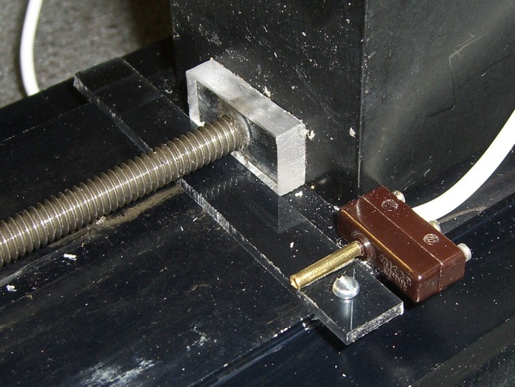
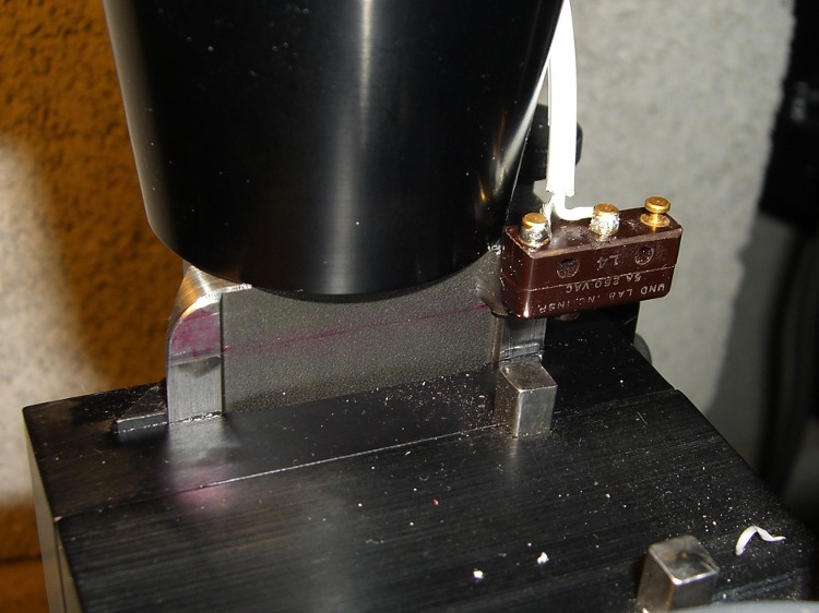
    Having hacked a jack in the Sherline motor driver box, this is what goes on the other end of the cable: the simplest possible tool length switch.

    I’ve seen all manner of exceedingly fancy and painstakingly constructed tool length switch stations, but it seems ordinary snap-action / tactile-feedback switches are repeatable enough for most purposes. I selected a switch from my stash with these qualifications:

    • physically small — fits on Sherline table
    • plastic button — avoid nicking the cutters
    • many more in the stash — not a special-order item
    • cheap – ’nuff said

    A few snippets of heat stink shrink tubing later…

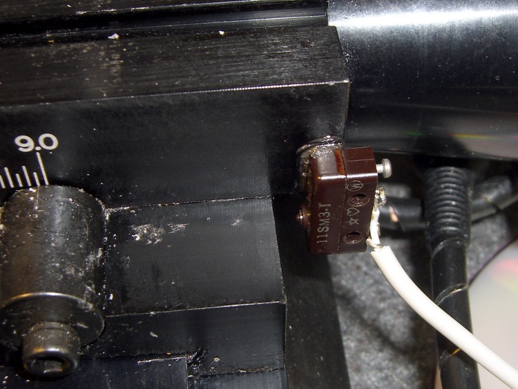
    Switch detail
    Switch detail

    After puzzling over the mounting, I snagged a chunk of aluminum U-channel from the heap, poked a 10-32 clearance hole in one end, and held the switch in place while slobbering brown hot-melt glue over it. The glue is rigid when cool, so the switch isn’t going anywhere, but it’s mounted with some air space below to allow crushing when the probe routine screws up.

    The button stands slightly proud of the U-channel, so even wide tools have side clearance. If the tool doesn’t stop when the switch trips (it could happen!), the entire switch will bend downward until the Z-axis drive stalls as the tool crushes the rubble or snags on the side of the U-channel.

    At which point I just cut the cable, hammer the hot-melt glue and switch rubble out of the U-channel, solder up another switch, blob it in place, and continue the mission… from scratch, though, because the stored tool height reference value will be kaput.

    The U-channel can be screwed down to a T-nut, clamped directly to the table, or affixed wherever it’s needed. If the Sherline had home switches, it’d be better to mount the probe switch in a fixed location somewhere, then use a fixture offset for the part, but I’m not there yet.

    The switch doesn’t have much overtravel: when the contacts activate with a tactile click, the button is pretty much bottomed out. However, unless you’re driving the tool into the switch at a dead run, it ought to stop moving fairly quickly.

    Back of the envelope: I have the Z axis acceleration set to (a sluggish) 3.0 in/s/s. Approaching the switch at 12 in/min = 0.2 in/s , it’ll screech to a halt in 67 ms = (0.2 in/s)/(3.0 in/s/s). Assuming the average velocity while stopping is 0.1 in/s, the distance works out to 7 mils, which shouldn’t pose a problem.

    Then drive up off the switch enough to clear the backlash and drive down at nose-pickin’ speed, so the axis stops pretty much instantly when the switch clicks.

    Some not-very-exhaustive testing suggests the repeatability for a single tool is well within 0.03 mm, about 0.001 inch, which is entirely satisfactory for my purposes.

    [Update: It’s pretty good, all things considered. A simple experiment is there.]

    The overall procedure:

    • Laser align XY to the part origin, home X&Y axes
    • Execute G49 to clear any existing tool length compensation
    • Insert first tool, align to Z=0 on part, home Z axis
    • Eyeball align XY to the switch with the tool just above
    • Jog Z comfortably high, execute G30.1 to set tool change location
    • Fire up your program!

    The program probes the first tool length and saves that as the reference length. Each subsequent tool change gets probed and the tool offset becomes the difference between the new length and the reference length.

    The initial probing routine:

    O<Probe_Init> SUB
    
    G49					( clear tool length compensation)
    G30					( to probe switch)
    G91					( relative mode for probing)
    
    G38.2 Z-90 F300		( trip switch on the way down)
    G0 Z1				( back off the switch)
    G38.2 Z-10 F10		( trip switch slowly)
    
    #<_ToolRefZ> = #5063	( save trip point)
    
    G90					( absolute mode)
    G30					( return to safe level)
    
    O<Probe_Init> ENDSUB
    

    Note that the G30 coordinates are stored in native units, which are inches for my Sherline mill. To get to that Z height (for safety, before moving) while using metric units:

    G0 Z[#5183 * 25.4]

    The G38.2 coordinates are stored in whatever units the G20/G21 mode calls for, so they can be applied directly to tool length compensation. That seems odd, as EMC assumes the tool table uses native units.

    There does not seem to be any way to determine which unit mode is active, although the probe speed depends on that setting. although I suppose I could set a global variable to the desired probe speed and leave it up to the G-Code program(mer) to get it right. Yeah, like that’ll work…

    Anyhow, each subsequent tool gets probed thusly:

    O<Probe_Tool> SUB
    
    G49					( clear tool length compensation)
    G30					( to probe switch)
    G91					( relative mode for probing)
    
    G38.2 Z-90 F300		( trip switch on the way down)
    G0 Z1				( back off the switch)
    G38.2 Z-10 F10		( trip switch slowly)
    
    #<_ToolZ> = #5063				( save new tool length)
    
    G43.1 K[#<_ToolZ> - #<_ToolRefZ>]	( set new length)
    
    G90					( absolute mode)
    G30					( return to safe level)
    
    O<Probe_Tool> ENDSUB
    

    With those two routines in hand, this demo code shows how it’s done…

    G21					( metric units)
    
    (msg,Verify origin at proper location, hit Resume)
    M0
    (msg,Verify G30.1 at tool change switch, hit Resume)
    M0
    (msg,Verify first tool installed, hit Resume)
    M0
    
    O<Probe_Init> CALL
    
    G0 X0 Y0 Z0
    (msg,Verify return to origin, hit Resume)
    M0
    
    M6 T2
    O<Probe_Tool> CALL
    
    G0 X0 Y0 Z0
    (msg,Verify return to origin, hit Resume)
    M0
    
    M6 T3
    O<Probe_Tool> CALL
    
    G0 X0 Y0 Z0
    (msg,Verify return to origin, hit Resume)
    M0
    
    M6 T4
    O<Probe_Tool> CALL
    
    G0 X0 Y0 Z0
    (msg,Verify return to origin...)
    M2
    

    The M6 Tx commands make use of a

    TOOL_CHANGE_AT_G30 = 1

    line in Sherline.ini, which tells the Axis automagic manual tool changer routine to traverse to the G30 position and pop up a prompt to (manually) change the tool. When you click OK, the subsequent CALL command invokes the tool length probe routine and away it goes.

    This whole lashup doesn’t have a lot of power-on hours, but I really like how it works!

    A tip o’ the cycling helmet to the folks behind EMC2…

  • Palm Zire 71 USB Cradle Charging Current Indicator

    Modified USB cradle with bargraph
    Modified USB cradle with bargraph

    The first time my first Zire 71 crapped out, I hacked this charging current display into the cradle so I could see when the mumble thing was actually charging. It turns out that the PDA makes its happy “I’m charging!” beep and overlays the charging indicator on the battery symbol even when there’s no +5 V connection to the PDA: you can leave it in the cradle all night and wake up to a dead battery in the morning.

    I hate it when that happens…

    The charging current meter is a classic LM3914 LED display driver and a surplus HP (from back when they were HP) 10-LED bargraph module.

    Here’s the schematic, such as it is, reverse-engineered from the as-built gadget…

    Charge current bargraph circuit
    Charge current bargraph circuit

    [Update: Something went wrong with the upload for that sketch; I think it’s OK now.]

    The general idea is to insert a 1-Ω resistor in the common return from the Zire’s charging contacts. The total current through the Zire, which is mostly battery charging current when it’s off, generates a voltage across the resistor. That voltage feeds the LM3914’s input, so the LEDs directly indicate the charging current.

    Fairly obviously, that resistor drops the external voltage by a smidge. As nearly as I can tell, the drop adds up to maybe a third of a volt, so the charging voltage is a tad lower than they expect. Seems to work just fine; the maximum charging voltage for a 3.7 V Li-Ion cell is pretty close to 4.2 V, so they’ve still got half a volt to play with.

    The two resistors and the trimpot add up to 1240 Ω, which sets the LED current to about 10 mA. The trimpot sets the voltage at the top of the LM3914’s internal resistor string to about 290 mV, although I measure the all-LEDs-on current at about 380 mA.

    Current meter overview
    Current meter overview

    Here’s what it looks like inside.

    The sense resistor hangs off the power input jack’s common pin, with the common lead from the PDA contact pins and the LM3914 input lead connected to the other end. The LM3914 common goes directly to the power supply common, not the hot end of the sense resistor.

    The 5.1 V lead from the power input jack still goes directly to the PDA contact pins, as well as the LM3914. I put a 22 Ω resistor in series with the LEDs to cut their power dissipation a bit. They’re plenty bright at 10 mA, so you might want to cut that down.

    Bargraph display detail
    Bargraph display detail

    The LED bargraph module fits neatly in a rectangular hole painstakingly drilled, sawed, and filed into the case, then held in place with a generous dollop of JB Weld epoxy. I taped it in place to keep the epoxy from oozing out while it was curing.

    The LM3914 is soldered directly to the display module, with flying wires and components soldered to the remaining pins.

    If I recall correctly, I held the Zire in position on the connector strip, got it charging, and then tweaked the trimpot until the display showed full scale.

    This was done in an absolute white-heat frenzy with the PDA’s battery going dead, but at least the exterior looks pretty good. The circuitry inside is a genuine hairball that has been working fine ever since, which makes it Good Enough.

  • Sherline Tool Length Probe: Adding a Jack

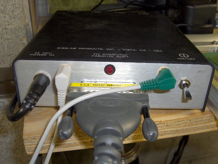
    Probe jack and switch
    Probe jack and switch

    I’ve been mulling over adding a tool length probe for a while and finally decided that the simplest approach might be the best: a momentary-contact pushbutton switch that pulls a parallel port input pin to ground.

    The motivation is that a simple switch seems to be repeatable enough for tool length probing and it’s cheap enough that I won’t form a deep emotional bond to it. When a probe crashes the switch, I can just pop another one in place without any heartache or putzing around for a day or three to build another over-elaborate probe station.

    The catch is that the Sherline motor driver box doesn’t include connections for any of the parallel port input pins.

    The choices seem to boil down to:

    • Adding a breakout board between the parallel port and the driver box or
    • Hacking the driver box to get access to the port pins

    Well, I’ve already pretty well hacked up my controller, as I wrote up in Circuit Cellar magazine (Aug & Oct 2004), so I don’t have much to lose… and the box is already in the shop!

    Probe to port pin 15
    Probe to port pin 15

    This picture shows the connection to pin 15 of the parallel port on the Sherline driver PCB. The driver doesn’t use that input pin (or any of the others, for that matter), which means the PCB doesn’t have a trace leading anywhere convenient. I ran the new wires through the connector mounting hole, rather than around the edge, and soldered them directly to the connector pins on the bottom of the board.

    The jack is an ordinary 1/8″ (3.5 mm, these days) stereo (3 conductor) jack, with lah-dee-dah gratuitous gold-flavored flashed plating; anything similar will work just fine.

    Connections:

    • Sleeve -> driver box
    • Ring -> circuit ground (pin 19 is convenient)
    • Tip -> pin 15, the probe input

    The cable shield connects only at the plug into the driver box, not at the switch end. That ensures there’s no current flowing through it and it can do a marginally better job of shielding the two conductors within. I’m reasonably sure that makes no difference whatsoever in this application.

    The cable got chopped out of an AV-interconnect dingus with all sorts of fancy connectors on the other end. It’s a surplus find, cost maybe a buck, and has the redeeming feature of sporting molded plugs that I don’t have to solder.

    The switch connections are soldered and insulated with heat stink shrink tubing. The general idea is that the driver box provides all the power, there’s no electrical contact with the mill table or spindle, and thus no reason to use fancy circuitry to solve a problem that’s not there.

    I did not add a capacitor across the switch contacts, figuring that I’d solve that problem when it happened. The common practice of putting a honkin’ big cap across switch contacts is bad practice: it effectively shorts the power supply across the contacts for a brief moment every time the switch closes. Some stored energy is good (it keeps the contacts clean), too much simply burns them away. ‘Nuff said.

    Probe jack - inside
    Probe jack – inside

    I marked a hole on the front panel symmetric with the LED, eased the circuit board out of the case and wrapped it in a shop rag to keep the swarf out, propped the case on the drill press table, and rammed a 1/4″ hole through the spot marked X with a step drill. Yeah, hand-held on the table, just like you’re never supposed to do.

    The force is strong with me…

    The (well, my) Sherline.hal file connects pin 15 to the probe sense input (maybe I defined that when I set things up; I don’t recall now), but it assumes the pin will be high when active. The parallel port pin has a built-in pullup resistor and a switch to ground makes it active when low. These two lines in my custom_postgui.hal file disconnect the high-active pin signal and connect the low-active pin signal.

    unlinkp parport.0.pin-15-in
    net probe-in parport.0.pin-15-in-not
    

    You do it that way to avoid changing the Sherline.hal file, which will be overwritten if you ever run the automagic configuration program again.

    If you’re doing this from scratch, just configure the whole thing using the configuration tool, it’ll set the HAL file properly and you won’t need any of that fiddling around.

    Tweak the Sherline.ini file to add support for tool changing with the G30 command:

    [EMCIO]
    TOOL_CHANGE_AT_G30 = 1
    

    Button everything up, then do a quick

    G91 G38.2 Z-10 F10

    and poke the button while the Z axis is in motion. The Z axis should stop instantly. If not, check your wiring.

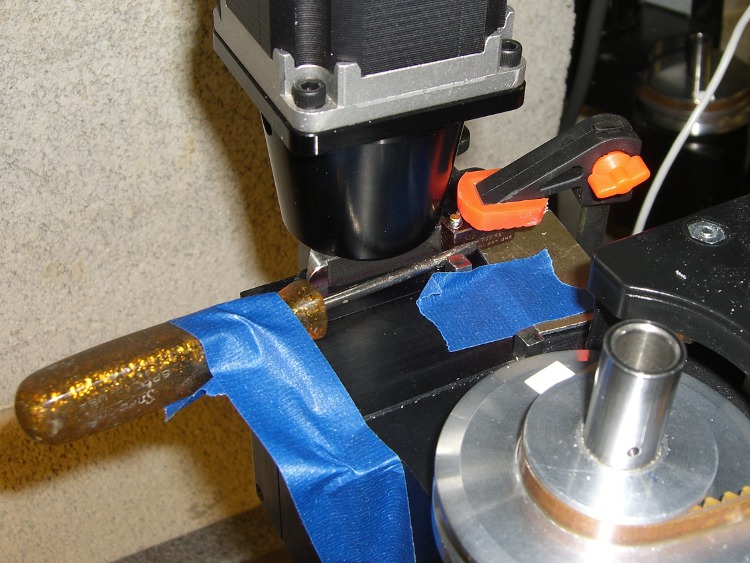
    Now, some Orc Engineering is in order: I need a low-budget fixture to put the switch in harm’s way.

  • Bicycle Reflector Adaptor Bushing

    Reflector on bushing
    Reflector on bushing

    After replacing the seat strut screws, I found a Round Tuit lying there on the workbench, right next to the rear reflectors I’ve been meaning to install for a truly embarrassing period.

    Recumbents don’t have the usual assortment of standard-sized tubing in the usual road-bike places, making common items like reflectors difficult to attach. The ideal spot on our bikes is at the base of the VHF/UHF antennas, right next to the white blinky LEDs, but, alas, that’s 20 mm in diameter and the reflector clamp barely shrinks down to a bit under 28.

    Turns out that a chunk of 1.5 inch PVC pipe has a 4 mm wall thickness, so wrapping a layer of that around the antenna base will do the trick. I whacked off a length of pipe, faced off both ends in the lathe, and put a shallow recess around the middle of the ring to capture the reflector clamp.

    By another rare coincidence, 1.5 inch PVC pipe has an ID of exactly 40 mm… so cutting the ring exactly along a diameter produces the right length. The catch is that the pipe isn’t flexible at all, but brandishing a heat gun in a threatening manner solves that problem.

    Reshaped bushing on mandrel
    Reshaped bushing on mandrel

    A random hunk of 3/4-inch aluminum rod is about 19 mm in diameter, so I chucked that in the lathe and shaped the saggy strip around it… wearing thick leather gloves.

    It springs out to 20 mm with no problem, slides right on, and grips reasonably well. I may add a strip of tapeless sticky (think double-sided tape without the tape: just the adhesive!) under the bushing if it wants to walk away.

    I made two of ’em, of course, and put a reflector on Mary’s bike while I was at it. Our young lady’s bike already has a reflector, although I should upgrade that bushing as well… it’s a layer of self-vulcanizing rubber tape that works perfectly, so this may take a while.

    I suppose I should buy a length of gray or black PVC pipe, but that’s in the nature of fine tuning.

  • X10 PHC02 Maxi Controller: Green LED

    PHC02 Circuit Board
    PHC02 Circuit Board

    Got the replacement X10 controller from the usual eBay source and it works fine, except it has a red LED that’s on unless it’s sending an X10 command.

    That’d be OK, except that I’ve spent the last few months associating a red LED at that spot on the dresser with a jammed X10 controller.

    Not to mention that red LEDs are sooo 20th Century…

    Four screws hold the baseplate in place; it takes a bit of prying to release the stiffening collars around the front screws and remove the baseplate. One more screw holds the circuit board in place.

    Surprisingly, they used the same metal-dome switch plates!

    Anyhow, with the board out, it’s easy to unsolder the red LED and replace it with a green one from my bag o’ mixed LEDs. It’s not quite the same shape and doesn’t have a big shoulder to keep it in place, but it’s good enough for me.

    New green LED
    New green LED

    The heat of soldering melted the thermoplastic glue that held the original LED in place. The new one isn’t quite as firmly bonded, but I don’t intend to jam a paperclip into the hole after shoving the LED out of the way.

    That was easy…

  • EMC2 Gamepad Pendant: Joystick Axis Lockout

    Nothing like sleeping on a problem. It turns out that a chunk of HAL code can do a nice job of locking out an inactive joystick axis.

    The general idea:

    • A priority encoder selects one axis when both go active simultaneously
    • The prioritized outputs set flipflops that remember the active axis
    • The active axis locks out the other one until they’re both inactive

    That way, you can start to jog either axis on a knob without worrying about accidentally jogging the other axis by moving the knob at a slight diagonal. I hate it when that happens.

    The other tweak is that the quartet of buttons on the right act as a “hat” for the Z and A axes, jogging them at the current maximum speed.

    Because it’s tough to accidentally push two buttons at once, there’s no need to lock them out. So you can jog diagonally by deliberately pushing adjoining buttons, but you must want to do that.

    Rather than dumping the whole program again, here are the key parts…

    Figuring out if a joystick axis is active uses the window comparators. It seems the idle counts value varies slightly around 127, so I relaxed the window limits. Should the window comparator go active with the knob centered, the buttons for that axis won’t produce any motion.

    net		x-jog-count-int	input.0.abs-x-counts	conv-s32-float.0.in
    net		x-jog-count-raw	conv-s32-float.0.out	wcomp.0.in
    setp	wcomp.0.min		125
    setp	wcomp.0.max		130
    net		X-inactive		wcomp.0.out				not.0.in
    net		X-active		not.0.out
    

    The priority encoder is just a gate that prevents Y (or A) from being selected if X (or Z) is simultaneously active. Here’s a sketch for the ZA knob:

    Axis priority encoder
    Axis priority encoder

    The active and inactive signals come from the window detectors. The sketch gives the K-map layout, although there’s not a whole lot of optimization required.

    The corresponding code:

    net		Z-inactive		and2.5.in0
    net		A-active		and2.5.in1
    net		A-select		and2.5.out				# select A only when Z inactive
    
    net		Z-inactive		and2.6.in0
    net		A-inactive		and2.6.in1
    net		ZA-Deselect		and2.6.out				# reset flipflops when both inactive
    
    net		Z-active		and2.7.in0				# set Z gate when knob is active
    net		A-gate-not		and2.7.in1				# and A is not already gated
    net		Z-set			and2.7.out					flipflop.2.set
    
    net		ZA-Deselect		flipflop.2.reset		# reset when neither is active
    net		Z-gate			flipflop.2.out				not.6.in
    net		Z-gate-not		not.6.out
    
    net		A-select		and2.8.in0				# set A gate when knob is active
    net		Z-gate-not		and2.8.in1				# and Z is not already gated
    net		A-set			and2.8.out					flipflop.3.set
    
    net		ZA-Deselect		flipflop.3.reset		# reset flipflop when both inactive
    net		A-gate			flipflop.3.out				not.7.in
    net		A-gate-not		not.7.out
    

    The flipflops remember which axis went active first and lock out the other one. When both axes on a knob return to center, the flipflops reset.

    The quartet of buttons produce binary outputs, rather than the floats from the Hat, so a pair of multiplexers emit -1.0, 0.0, or +1.0, depending on the state of the buttons, for each axis.

    setp	mux2.6.in0	0.0
    setp	mux2.6.in1	-1.0
    net		A-btn-neg		input.0.btn-trigger		mux2.6.sel
    net		A-btn-neg-value	mux2.6.out				sum2.1.in0
    
    setp	mux2.7.in0	0.0
    setp	mux2.7.in1	1.0
    net		A-btn-pos		input.0.btn-thumb2		mux2.7.sel
    net		A-btn-pos-value	mux2.7.out				sum2.1.in1
    
    net		A-jog-button	sum2.1.out
    
    net		A-btn-neg		or2.1.in0
    net		A-btn-pos		or2.1.in1
    
    net		A-btn-any		or2.1.out				or2.2.in0
    net		A-gate			or2.2.in1
    net		A-motion		or2.2.out
    

    The A-motion signal is true when either of the A jog buttons or the A joystick axis is active. That gates the MAX_ANGULAR_VELOCITY value to halui.jog-speed, rather than the default MAX_LINEAR_VELOCITY. Or, depending on the state of the toggle from the two joystick push switches, 5% of that maximum. A mere 5% may be too slow for the A axis, but it’ll take some experience to determine that.

    With that in hand, the final step is gating either the knob or the button values to halui.jog.*.analog.

    net		Z-jog-button	mux2.8.in0
    net		Z-jog-knob-inv	mux2.8.in1
    net		Z-gate			mux2.8.sel
    net		Z-jog			mux2.8.out				halui.jog.2.analog
    
    net		A-jog-button	mux2.9.in0
    net		A-jog-knob		input.0.abs-z-position	mux2.9.in1
    net		A-gate			mux2.9.sel
    net		A-jog			mux2.9.out				halui.jog.3.analog
    

    The complete source file (Logitech Dual Action Gamepad – joystick axis lockout – custom_postgui-hal.odt) is over on the G-code and Suchlike page, so you can download it as one lump. It’s an OpenOffice document because WordPress doesn’t allow plain text files.

    I loves me my new joggy thing!

  • Improved Sherline Way Bellows

    What with all the milling going on lately, I decided to replace the crusty bellows on the Sherline mill. The previous design worked reasonably well, but I’ve had a few tweaks in mind for a while.

    Herewith, a PDF file with some Sherline Bellows – Improved:

    • Color coded lines so you know which way to fold them!
    • Unlined side up for a neat look
    • Fits on Letter and A4 sheets
    • Taping cuts and hints

    The PDF page size is about 8×10 inches; call it 204×280 mm. Print it without scaling and it should just barely squeak onto the sheet. If you don’t have a full-bleed printer, the tips of the sides may get cropped off, but you can extrapolate easily enough.

    Some assembly required:

    • Cut it out
    • Fold the central valleys (red) first, flatten it out again
    • Fold the central ridges (blue) next
    • Pleat the whole thing into a half-inch tall stack
    • Squash it into a neat package to harden the folds
    • Fold the tips along one side
    • Fold the tips along the other side
    • Squash the folds again
    • Make the saddle cuts & fold the tabs
    • Apply double-stick tape as noted (some on back)
    • Install on your cleaned-up mill
    • Admire!

    The tip folding is the trickiest part. Basically, flip the first tip from a ridge to a valley, then chase the little transition folds into place. Repeat for each tip along that side, then do the other side.

    It gets easier after you fumble around for a while.

    My nimble-fingered daughter has offered to fold ’em for you. Stick a few bucks in an envelope and mail it to me; we’ll mail back two folded sets (two each, front and rear bellows) for your amusement. Kid’s gotta earn her college money somehow…

    Address? Go to the QRZ.com database and search for my amateur radio callsign: KE4ZNU. Cut, paste, that was easy.

    For the do-it-yourselfers, start with the PDF file in the link above. That’s the easiest way to get the correct scaling. The tabs on the ends should be 4.0 inches across on the printed page.

    Rear Bellows
    Rear Bellows
    Front Bellows
    Front Bellows

    Here are some 300 dpi PNG files, but you’re on your own for scaling.

    If you want the original Inkscape SVG files, drop me a note.