Ed Nisley's Blog: Shop notes, electronics, firmware, machinery, 3D printing, laser cuttery, and curiosities. Contents: 100% human thinking, 0% AI slop.
Tag: Improvements
Making the world a better place, one piece at a time
The Third Eye Hardshell Mirror was designed back in the day when Bell Helmets had actual hard plastic shells over a foam core, with a lip around the shell’s edge. These days, helmets consist of an elaborate foam structure with a paper-thin plastic covering. Mary’s helmet is like that, but it has a visor and I figured the mounting clamp might grab onto that.
It almost worked, but the edge of the clamp tapered the wrong way: tightening the screw tipped the clamp away from the visor lip.
Solution: chop off the offending part of the clamp, file off the sharp edges, and screw it in place. Works like a champ.
I’m not convinced this mount will survive the test of time, though. We already know that the clever ball joint will eventually lose its griptivity, but that’s fixable.
This pic shows that the mirror attaches to the boom through a clever ball joint that allows both rotation around the mirror’s long axis and a slight amount of tilt. Unfortunately, after a few years, the ball stem breaks and at least one of the socket petals snaps. It’s a nice plastic design that’s totally unsuited to a few years of more-or-less daily bicycle travel.
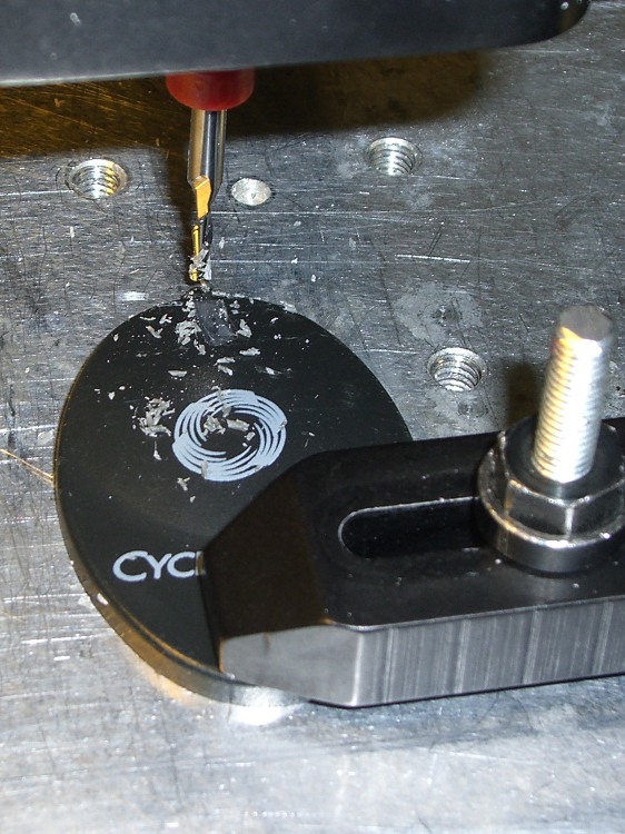
The repair was easy enough, particularly because I think the boom has enough adjustment range to handle the job on its own (and I don’t care about how it looks). I filed off the stem stub and milled a slot for a 2-56 machine screw along the back edge.
Milling slot for screw
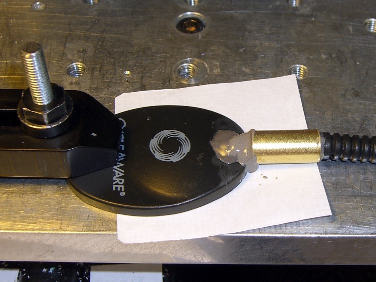
Then you just slide a brass tube from the cutoff box over the end of the boom around some JB Weld epoxy, shove the screw into the blob, align the mirror with the boom, and let it cure.
Reinforced attachment
Although it’s not shown here, the helmet attachment is aligned with the mirror at right angles to the helmet bracket. That puts it in roughly the proper position with the boom bent as usual.
I don’t actually plan to use this one for anything, but if I need a somewhat scuffed mirror in a pinch, well, it’s in the box!
I’m in the process of reworking the interface box between the amateur radio HTs on our bikes and our helmet-mounted earbud & mic lashup. Mary needed a new helmet before I got the new interface ready, soooo there’s an adapter cable in the middle.
This time around, the helmet cable uses a male USB-A connector, rather than a female 6-pin Mini-DIN PS/2 keyboard connector. Either one is cheap & readily available as assembled cables, which gets me out of soldering teeny little connector pins. These days, though, USB cables are more common.
The motivation for a non-latching, low-extraction-force connector at the helmet is that when (not if) you drop the bike, the helmet doesn’t tie your head to the bike and snap your spine. Falls on a recumbent are much less exciting than on an upright bike, but you still want the bike to go that-a-way while you go this-a-way. Been there, done that.
The old helmet cable connector: female 6-pin mini-DIN. The wire color code is not standardized. Viewed from rear of female connector or the front of the male connector, with the key slot up:
 ear com - Gn   5  |_|  6  K - ear hot
 mic com - Or   3  key  4  Y - mic hot
        gnd - Bn  1   2  R - gnd
The new helmet cable connector: male USB-A. Mercifully, they standardized the wire colors. Looking at the front of the male USB-A connector with the tab down and the contacts up, the pins are 4 3 2 1:
1 – R – ear hot
2 – W – mic hot
3 – G – mic com
4 – K – ear com
The female USB-A connector is exactly the same.
That arrangement should produce the proper twisted pairs in a USB 2.0 cable, but all the USB cables I’ve seen so far lay all four wires in a common twist inside the shield. Maybe it’s the cheap junk I buy, huh?
It’s worthwhile to scribble some color in the background of the trident USB symbol so it’s easier to mate the connectors.
Easy-align USB connectors
Memo to Self: verify the connections & proper operation before shrinking the tubing!
In the unlikely event you’re keeping track of this, slashing the total volume of email made Kmail much more competent: it hadn’t trashed an index file in, oh, weeks…
Until it happened again.
I don’t know that 30 days of email is magic, but 64 MB worked much better than 3 GB. The offending folder has all of 6 MB and 280 files, which puts a pathetic upper bound on Kmail’s good behavior.
Anyhow, Kmail still screws up its indexes, but … it’s better than it was.
You’d think this would be an important thing to get right, but the KDE apparat has far more important things to worry about. Eye candy, as nearly as I can tell.
I use Kmail because it’s one of the few email readers that stores messages in maildir format. That’s important with large email collections, because mbox, the other choice, tucks all the messages into a single honkin’ big file (perhaps one file per folder). That doesn’t work well with a daily backup strategy, because each message changes the file and triggers a backup of the whole thing. Maildir format means backing up only the new messages, which makes far more sense.
But, if this blank email thing continues, it’s time to move on…
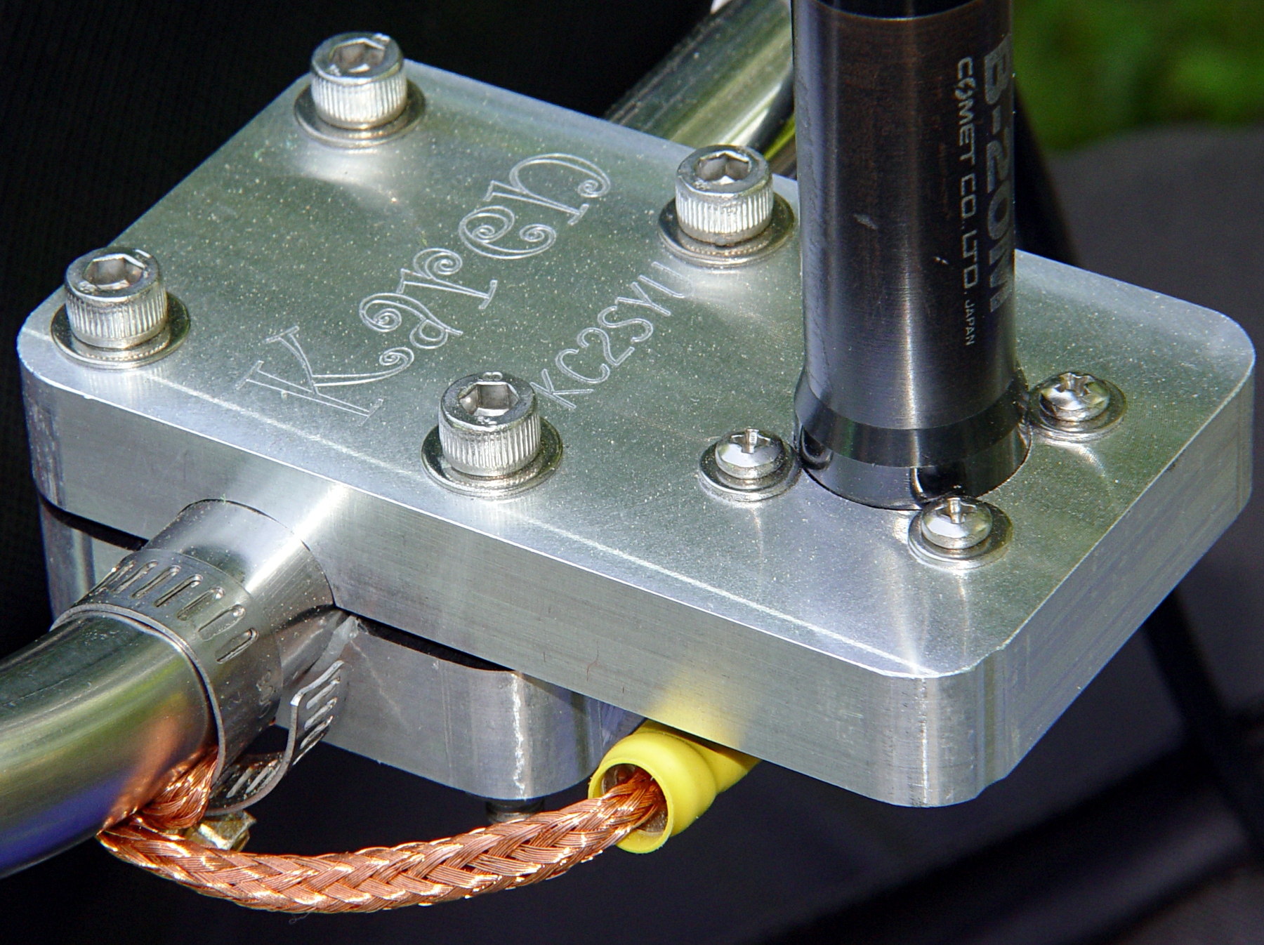
Quite a while ago, I built this slab mount to hold an amateur radio antenna on our daughter’s Tour Easy. It worked fine until the bike blew over and whacked the antenna whip against something solid, at which point the mast cracked.
The antenna screws into an ordinary panel-mount UHF connector secured to the bottom of the slab, with a hole through the slab just large enough to accept the antenna mast. That put all the mechanical stress on the slab, not the connector.
Modified antenna mounting plate
Alas, the new antenna had a slightly different mast outside diameter, so I machined a new adapter to clamp the connector atop the slab. The antenna screws down into the adapter against a brass washer, again keeping the strain on the fitting.
I recently found the commercial mobile antenna cable that I’d been meaning to use on her bike, which required Yet Another Modification to that slab. It turns out that the UHF connector on the cable expects to be secured to sheet metal found in a car body, rather than a half-inch aluminum plate: the threads aren’t long enough!
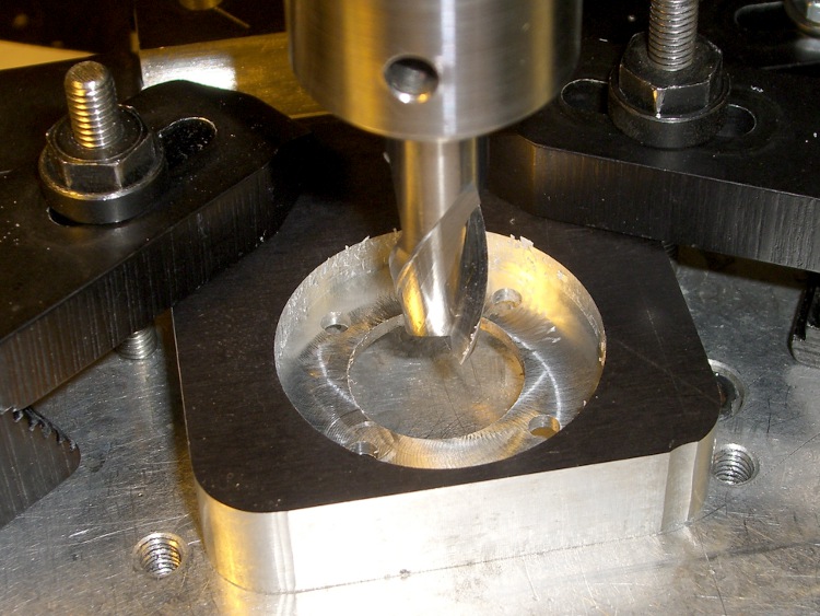
So I machined circular recesses on the top and bottom to hold the mounting nut and washer, respectively, with 2 mm of aluminum remaining in the middle of the slab.
Milling top recess
The recesses are just fractionally larger than the nut & washer, so most of the stress gets transmitted directly to the slab. Even in the high-vibration bicycle environment, I think there’s enough meat in there to prevent fatigue fractures.
Milling bottom recess
I recycled a G-Code routine I’d written to chew out circular recesses. It does a bit of gratuitous (for this application, anyway) spiraling in toward the center, but got the job done without my having to think too much.
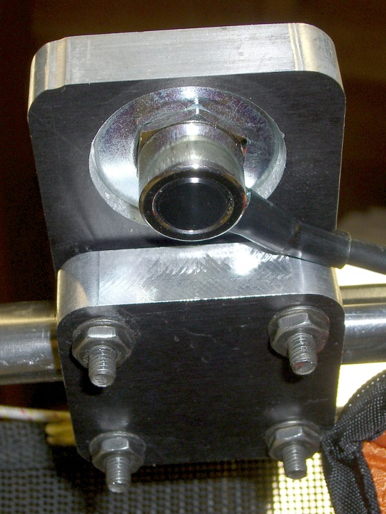
The bottom view shows the washer in action. The recess is deep enough that the cable just barely clears the slab.
Modified mounting plate – bottom
The top view shows the recessed mounting nut. The nut has an O-ring around the connector threads, but the water will probably drain out through the four through-holes left over from the old panel-mount connector.
Modified mounting plate
I turned the top nut down as far as I could with a wrench & (ugh) needle-nose pliers, then tightened the bottom nut about 1/3 turns with a wrench.
You’re not supposed to notice the crispy edges on the PVC bushing holding the reflector to the antenna mast. The high setting on that heat gun is a real toaster…
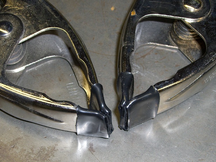
The OEM padding on the ends of my spring clamps wore off long ago; it was some sort of entirely-too-soft dipped plastic.
Some large-diameter heatshrink tubing seems like it ought to be a good replacement… the tips are a bit floppy, but maybe that’s not entirely a Bad Thing.
Having mounted & wired the switches, the next step involves defining the homing sequence & configuration for each axis. All this goes in Sherline.ini and is adapted from the doc there.
The travel limits are somewhat empirical and I think the Y axis will require some adjustment due to the tooling plate switch extender gadget.
The HOME_SEARCH_VEL values may be a bit too high, given the rather lethargic 5.0 in/sec^2 acceleration I’m using for X & Y, with just 3.0 for Z. I’ve heard the occasional thwack as the switch trips, so maybe 20 mils of overtravel isn’t quite enough.