
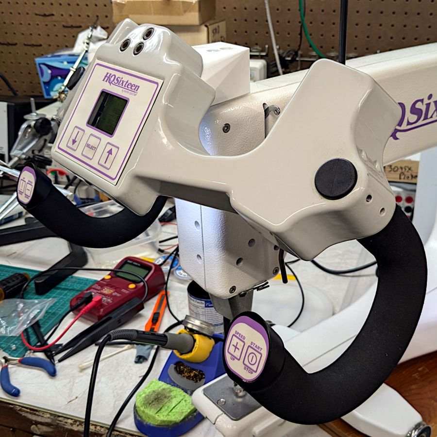
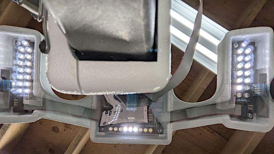
So as to not bury the lede, I remounted the front handlebar unit of Mary’s Handi-Quilter HQ Sixteen long-arm sewing machine so she can see the control panel with its small LCD:
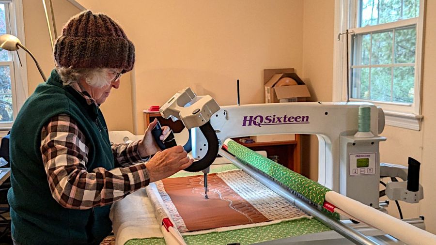
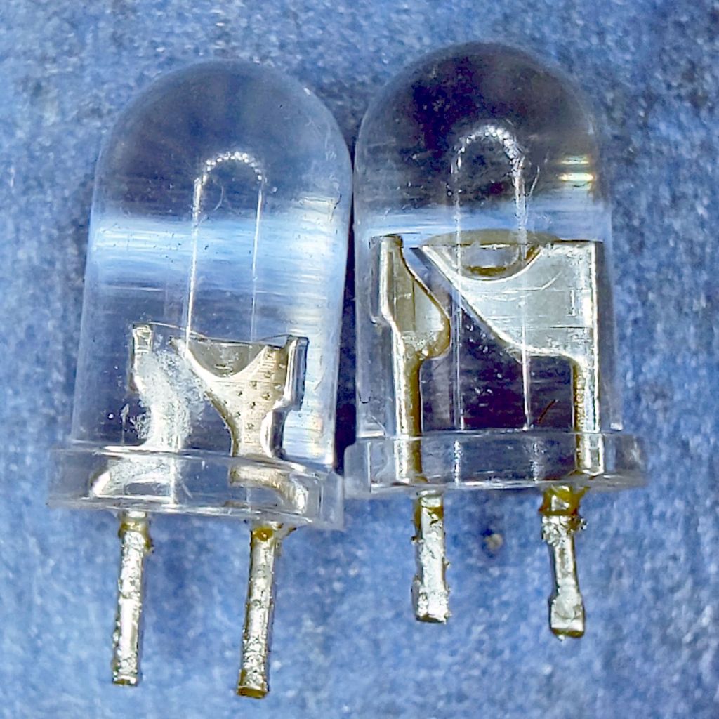
The new and old white LEDs produce distinctly different colors and intensities on the practice quilt fabric.
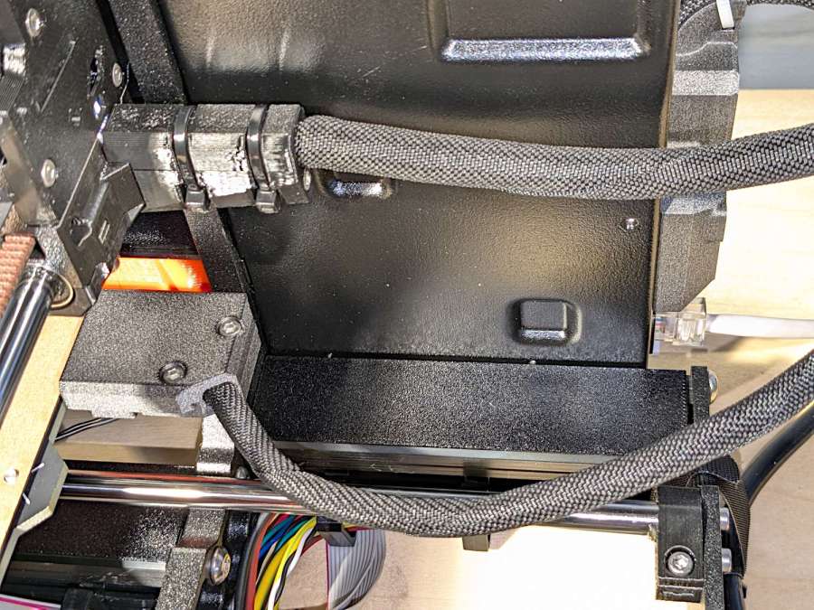
The original HQ Sixteen design bolted squarely atop the arm:
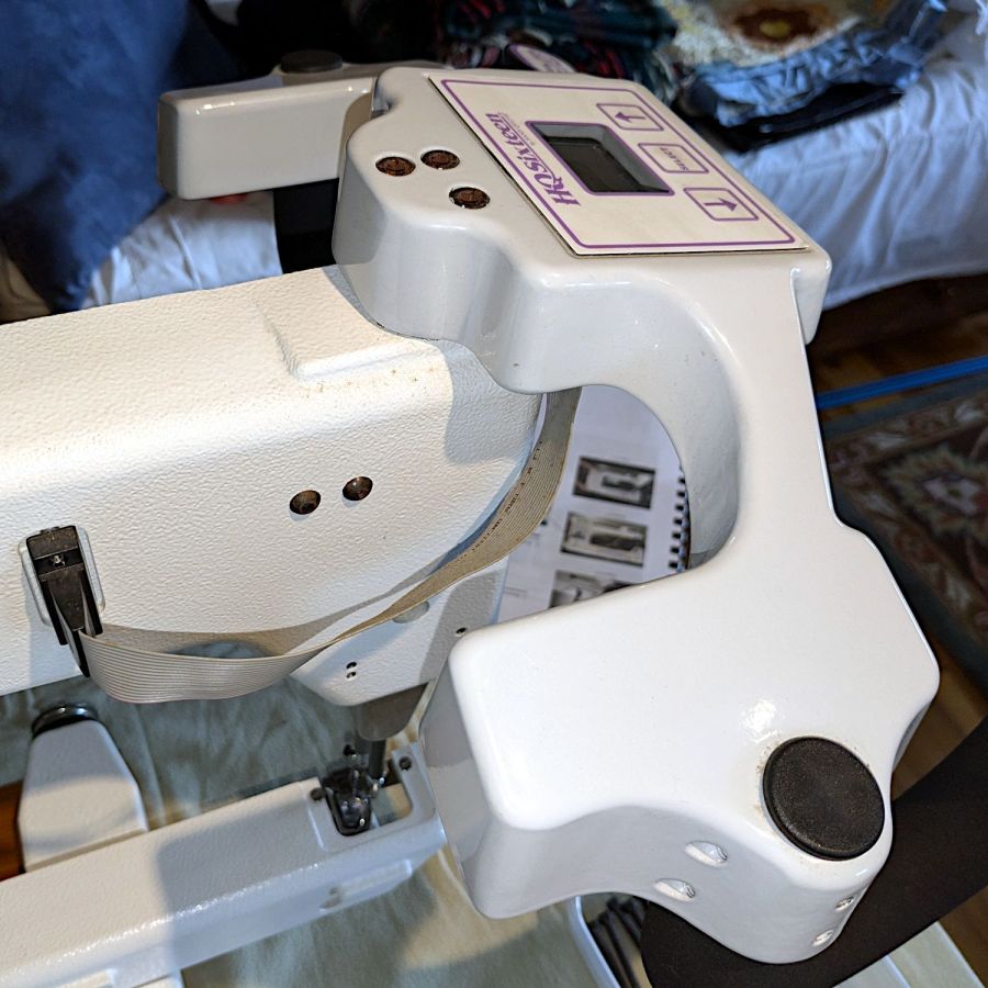
The control surface is, admittedly, angled slightly forward, but Mary was unable to see the lower few lines of the LCD without standing on tiptoe.
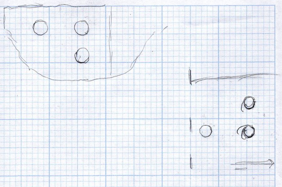
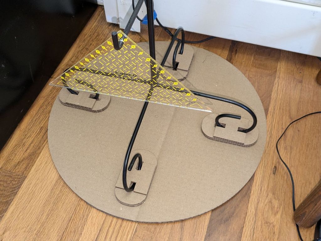
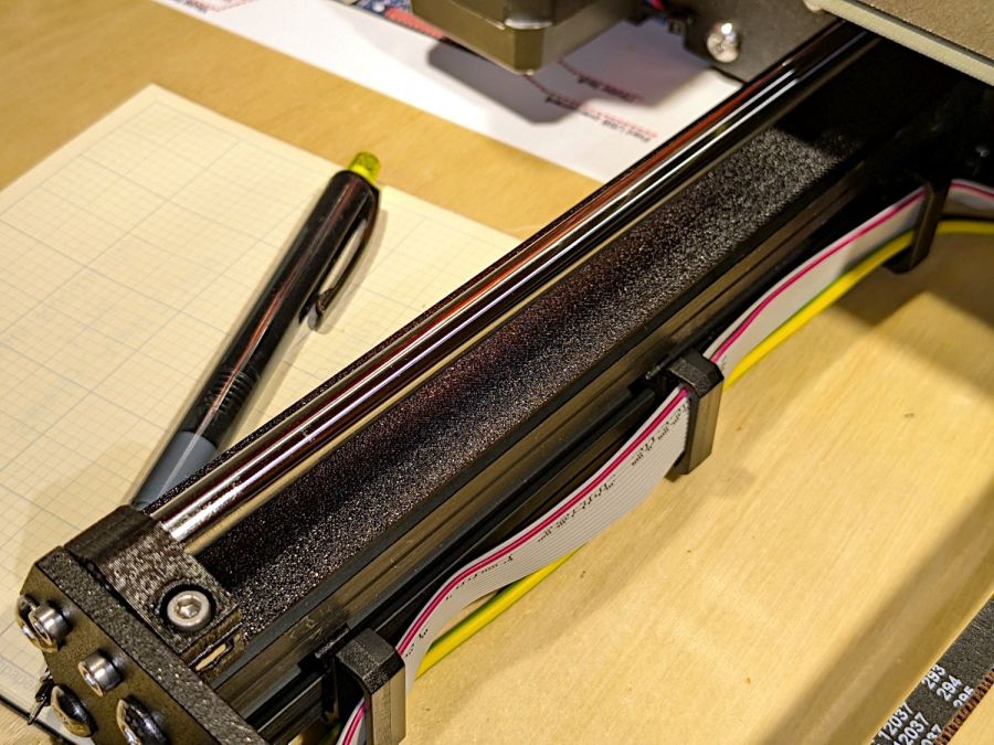
Begin with a crude tracing of the mating surfaces:
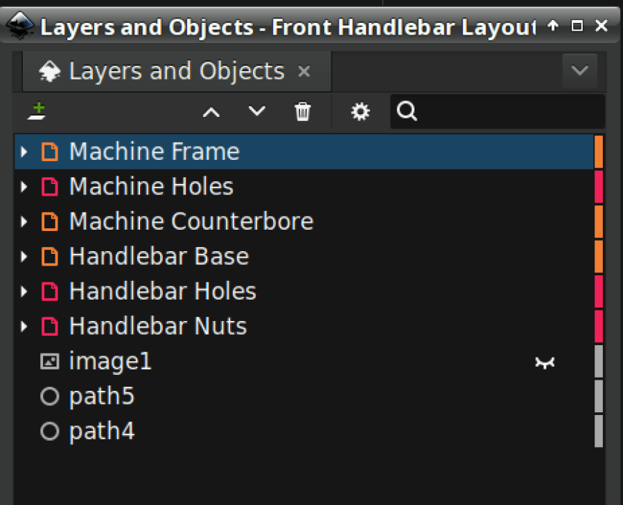
Import the image into Inkscape and lay some shapes on it:

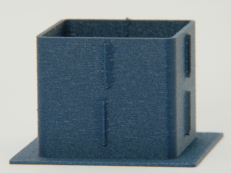
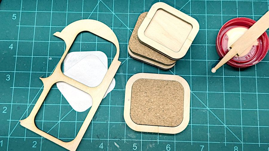
Import the SVG into LightBurn and cut templates to verify the hole positions:

Obviously that took more than one try.
Rationalize the outlines, clean things up, and organize the shapes into useful named layers:
Save as an Inkscape SVG, import into OpenSCAD, and extrude the layers defining all those shapes into a solid model:
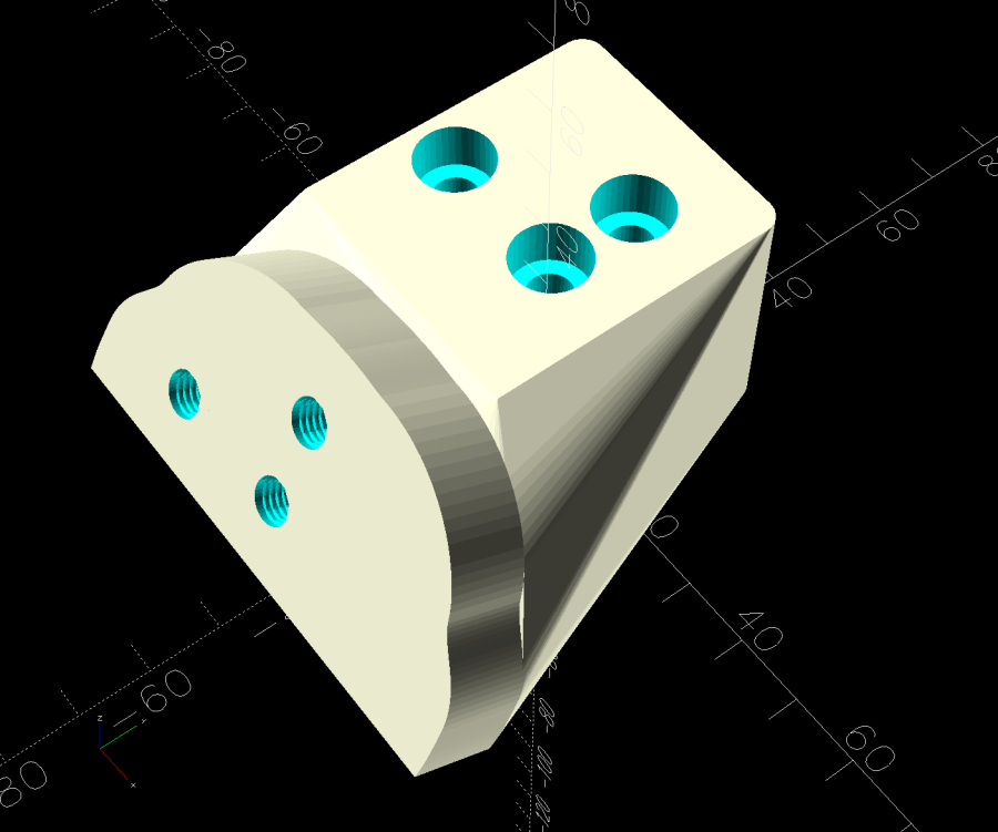
That’s the most recent iteration; earlier ones appear in various pix.
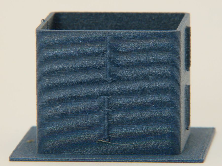
I had intended to use either square nuts or heat-set inserts, but it turned out to be easier to just slam BOSL2 threaded nuts into the front plate and be done with it:
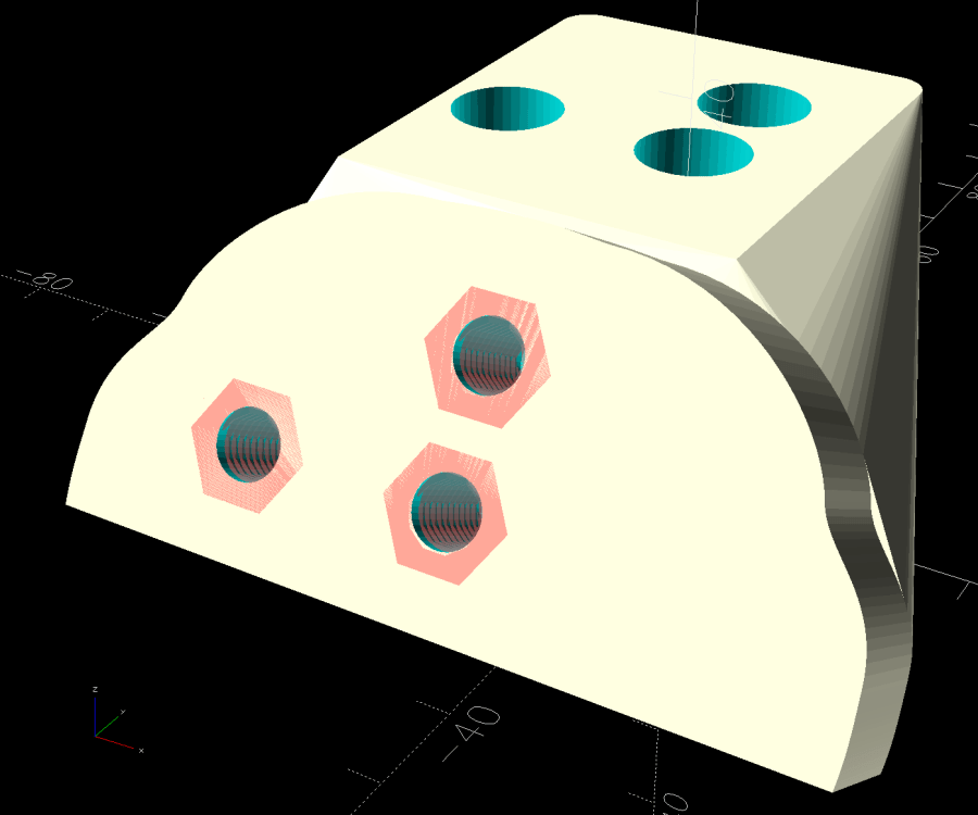
The trick is to sink the nuts around a hole sized slightly larger than the screw’s nominal diameter, letting the threads fill empty space.
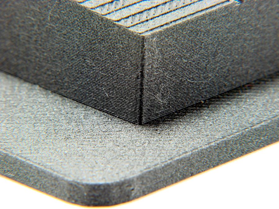
The handlebar base is mounted symmetrically along the machine arm centerline aligned with the two screws on the right. The rear block is offset to the left to clear the machine cover on the right, so the hull() wrapped around the two looks weird.
The front plate stands proud of the rest by dint of incorporating only a small slice of its back face into the hull() filling the gaps between the two. It’s not particularly stylin’, but it’s pretty close.
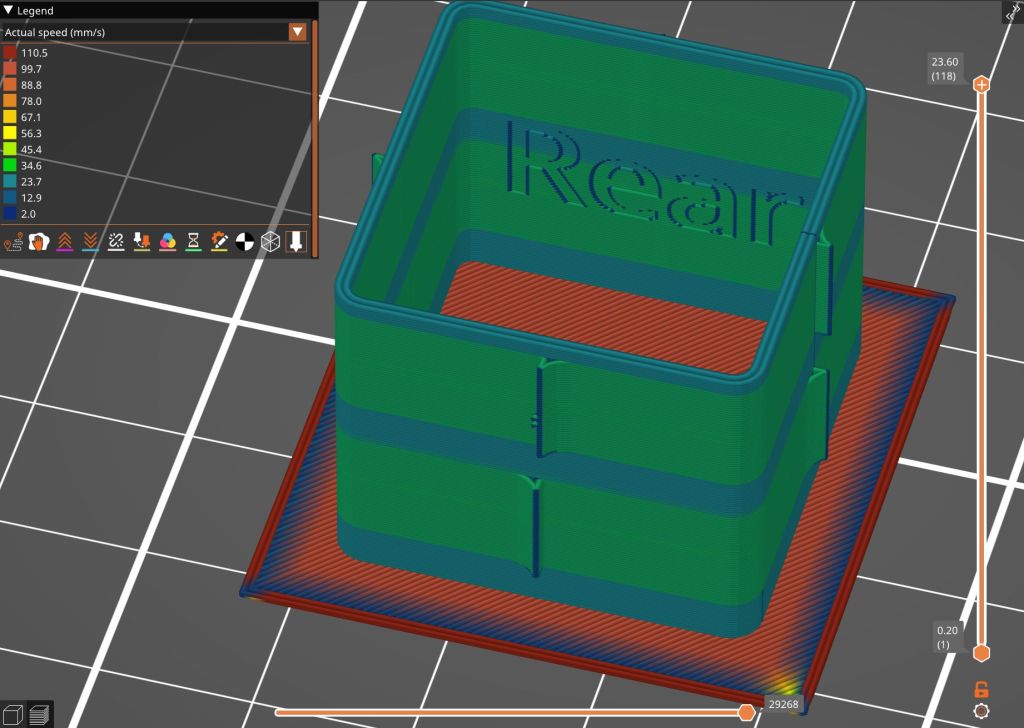
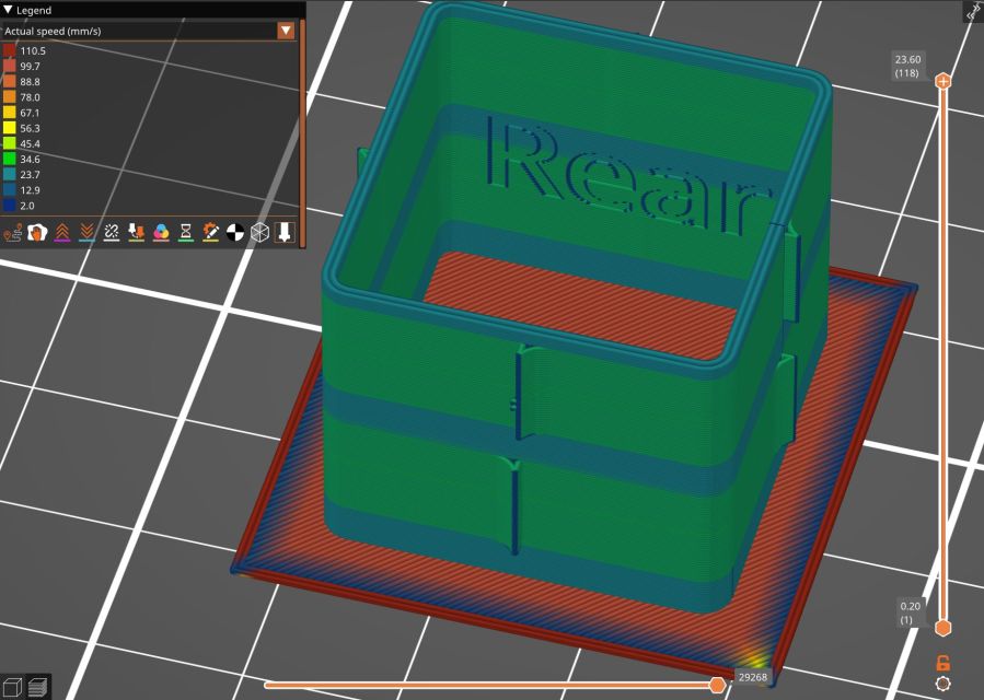
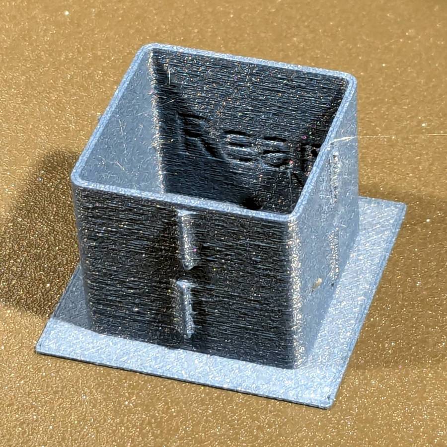
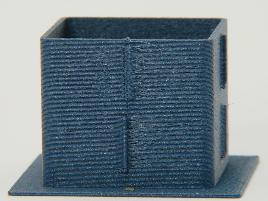
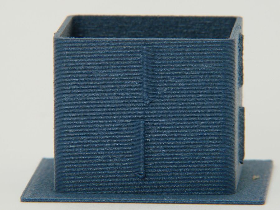
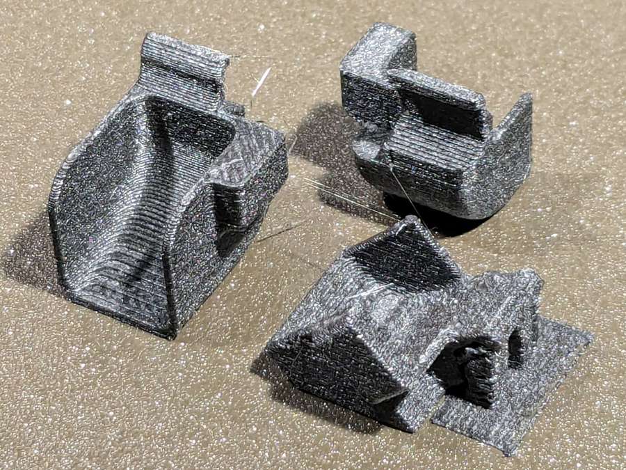
Finding the correct angle for the front plate required a couple of iterations, but they all built successfully:

Putting the threaded holes vertical created nicely formed threads that accepted the screws without hassle.
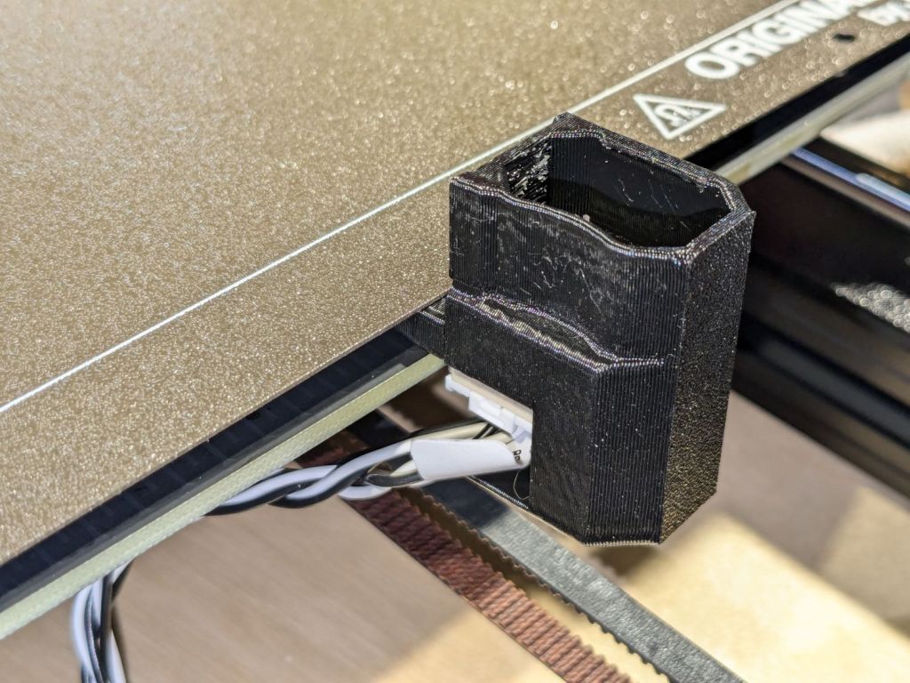
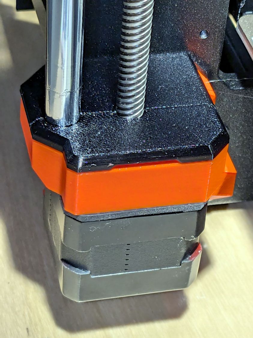
The block screws firmly to the arm and the handlebar unit screws to the block:

The display now faces front:
I eventually replaced those black oxide screws with shiny stainless ones, just for pretty.
The nine LEDs under the display now do a great job of lighting up the front of the machine’s arm, rather than the fabric at the needle, but fixing that will be a whole ‘nother project.
The handlebar grips with their control buttons now tilt at a somewhat inconvenient angle, which is also a whole ‘nother project.
Early reports from the user community are overwhelmingly positive.
The OpenSCAD source code and the SVG layout as a GitHub Gist:
| // Handiquilter HQ Sixteen front handlebar base mount | |
| // Ed Nisley – KE4ZNU | |
| // 2024-11-22 | |
| include <BOSL2/std.scad> | |
| include <BOSL2/threading.scad> | |
| Layout = "Show"; // [Build,Show,Block,Holes] | |
| HandlebarOffset = [0,-30.0,14.0]; // pure empirical values | |
| HandlebarAngle = [60,0,0]; | |
| FrameBlockThick = 35.0; // how much meat they need | |
| HandlebarThick = 12.0; | |
| /* [Hidden] */ | |
| Holes = [[-19.0,0,0],[0,0,0],[0,12.5,0]]; // Must match SVG hole coordinates | |
| FrameCenter = [-45,-65]; // coordinates of corner hole center | |
| HoleCenter = [-40,-20]; | |
| Protrusion = 0.1; | |
| module AdapterBlock() { | |
| union() { | |
| hull() { | |
| linear_extrude(height=FrameBlockThick,convexity=10) | |
| translate(FrameCenter) | |
| import("Front Handlebar Layout.svg",layer="Machine Frame"); | |
| translate(HandlebarOffset) | |
| rotate(HandlebarAngle) | |
| linear_extrude(height=0.05*HandlebarThick,convexity=10) | |
| translate(HoleCenter) | |
| import("Front Handlebar Layout.svg",layer="Handlebar Base"); | |
| } | |
| translate(HandlebarOffset) | |
| rotate(HandlebarAngle) | |
| linear_extrude(height=HandlebarThick,convexity=10) | |
| translate(HoleCenter) | |
| import("Front Handlebar Layout.svg",layer="Handlebar Base"); | |
| } | |
| } | |
| module AdapterHoles() { | |
| linear_extrude(height=FrameBlockThick,convexity=10) | |
| translate(FrameCenter) | |
| import("Front Handlebar Layout.svg",layer="Machine Holes",convexity=2); | |
| translate([0,0,FrameBlockThick – 7.0]) | |
| linear_extrude(height=7.0 + Protrusion,convexity=10) | |
| translate(FrameCenter) | |
| import("Front Handlebar Layout.svg",layer="Machine Counterbore",convexity=2); | |
| translate(HandlebarOffset) // cut clearance for nut threads | |
| rotate(HandlebarAngle) | |
| linear_extrude(height=HandlebarThick + Protrusion,convexity=10) | |
| translate(HoleCenter) | |
| import("Front Handlebar Layout.svg",layer="Handlebar Holes",convexity=2); | |
| } | |
| module Adapter() { | |
| union() { | |
| difference() { | |
| AdapterBlock(); | |
| AdapterHoles(); | |
| } | |
| # translate(HandlebarOffset) // add threads inside holes | |
| for (c = Holes) | |
| rotate(HandlebarAngle) | |
| translate(c) | |
| threaded_nut(10.0,6.2,HandlebarThick,1.0, // flat size, root dia, height, pitch | |
| bevel=false,ibevel=false,anchor=BOTTOM); | |
| } | |
| } | |
| // Build things | |
| if (Layout == "Block") | |
| AdapterBlock(); | |
| if (Layout == "Holes") | |
| # AdapterHoles(); | |
| if (Layout == "Show") | |
| Adapter(); | |
| if (Layout == "Build") | |
| rotate([180,0,0] – HandlebarAngle) | |
| Adapter(); |


