Ed Nisley's Blog: Shop notes, electronics, firmware, machinery, 3D printing, laser cuttery, and curiosities. Contents: 100% human thinking, 0% AI slop.
Tag: Improvements
Making the world a better place, one piece at a time
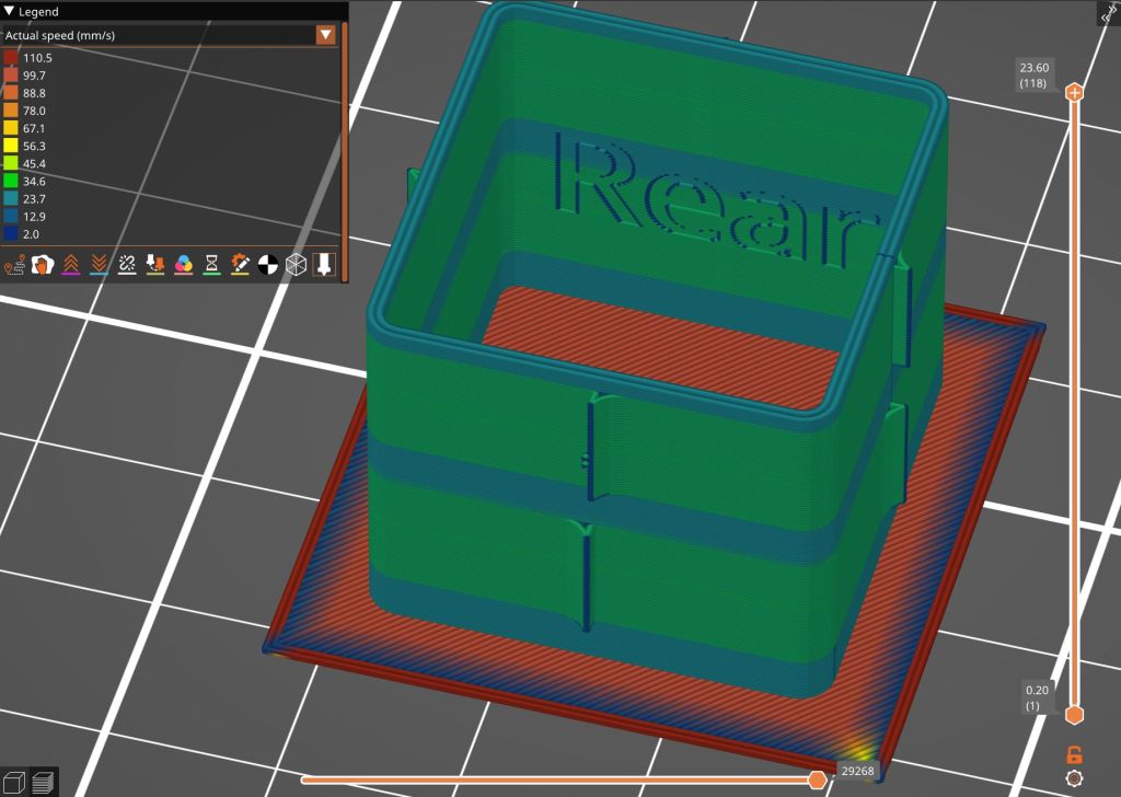
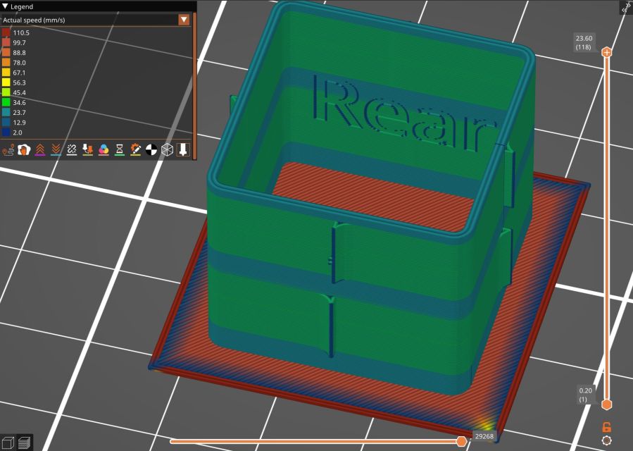
Loading the STL into PrusaSlicer, adding a text label to remind me which way it printed, then slicing with my PETG-CF profile shows the “Actual Speed”, which seems to take acceleration into consideration:
PrusaSlicer preview – actual speed
The colors in the legend don’t quite match the colors on the model, but the greenish layers with the jolts trundle along in the mid-20 mm/s range and the blue-ish straight-through layers at 30-ish mm/s.
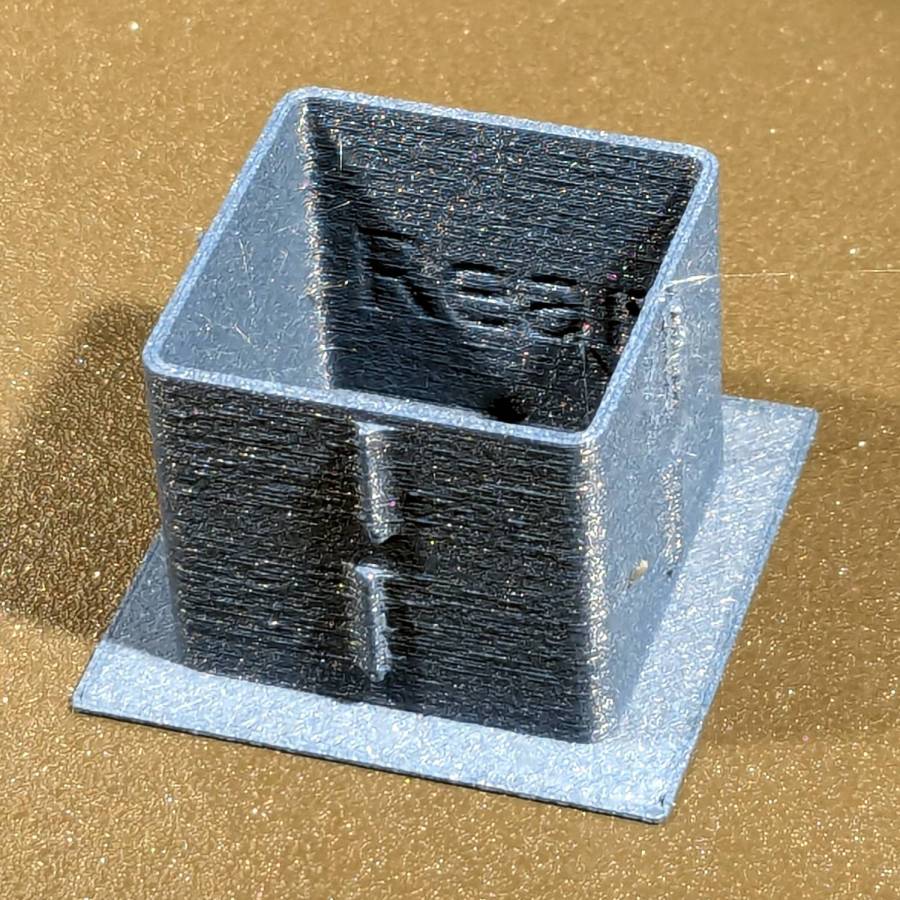
Eryone PETG-CF has a somewhat fuzzy appearance that seems not characteristic of other brands, so I’ll try something else when these spools run out:
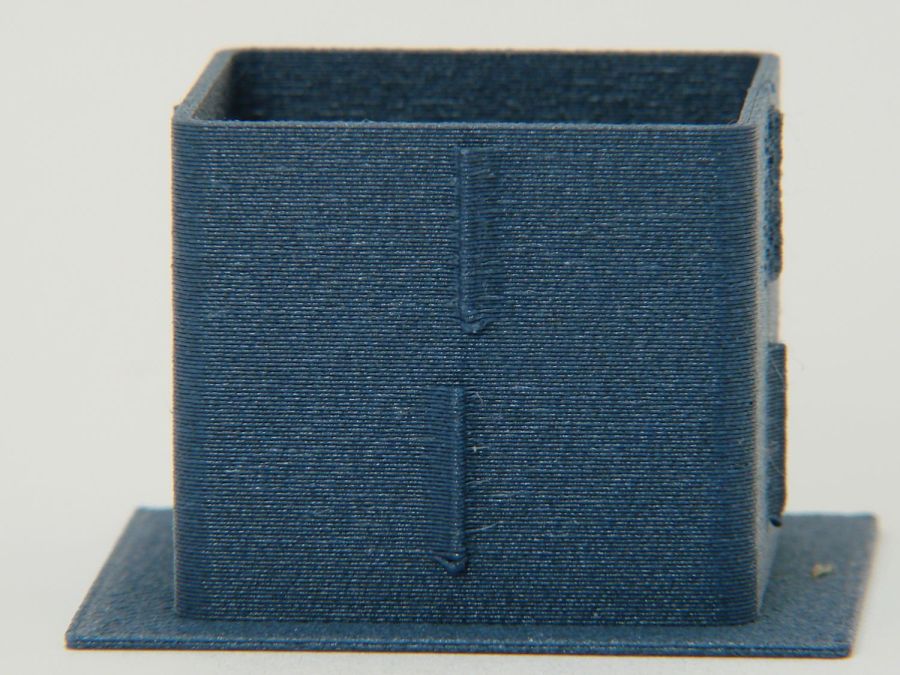
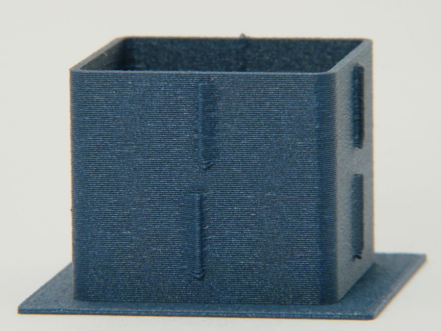
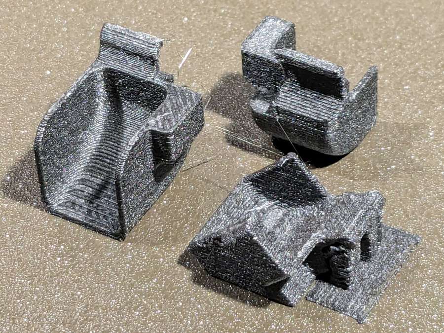
MK4 Resonance Test Box – overview
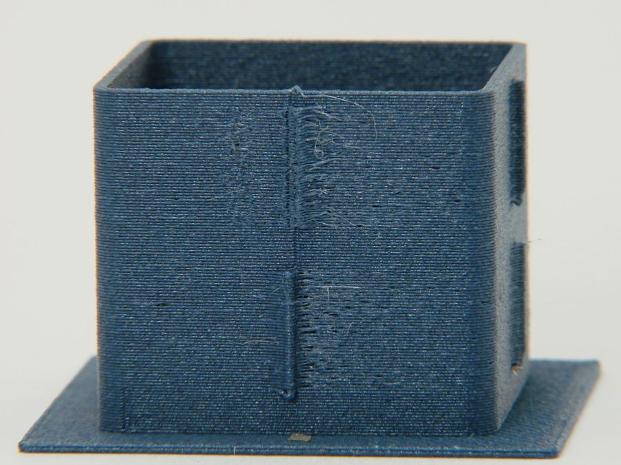
The right side of the box (as oriented on the platform) got all the layer retractions and came out festooned with PETG hairs:
MK4 Resonance Test Box – right side
You can check my labels by tracking the small retraction zit sticking up from the top layer; I got it wrong the first time. Open the images in a new tab to see more pixels.
The front:
MK4 Resonance Test Box – front side
The left:
MK4 Resonance Test Box – left side
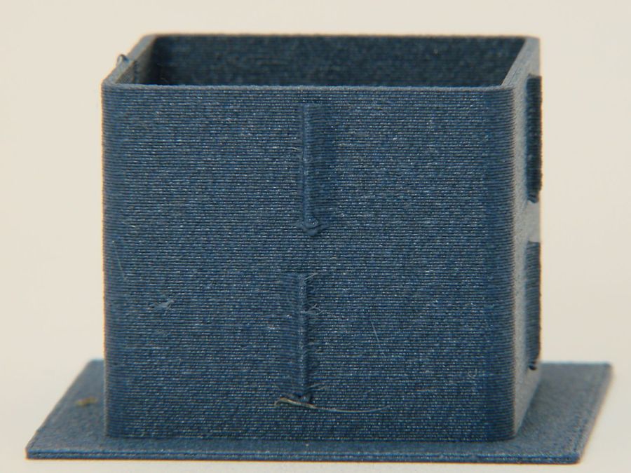
And the rear:
MK4 Resonance Test Box – rear side
You can barely see the shadow of the “Rear” text on the surface, even though the wall is two threads thick and the text is indented by 0.2 mm, about half the thread width.
As far as I can tell, the MK4 Input Shaper compensation does a great job of suppressing resonance or wobble in all directions.
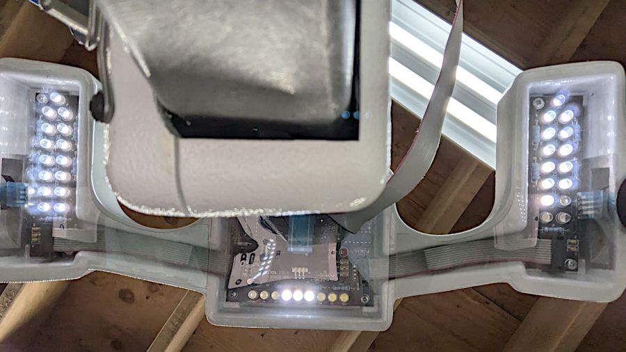
Judging from the dates codes on the ICs inside, Mary’s HandiQuilter Sixteen long-arm machine is about two decades old and many of the white LEDs in the front handlebars have gone dark:
HQ Sixteen – dead handlebar LEDs
The vertiginous view looks upward into the handlebar at the top of the machine (more on this later). The PCBs run strings of three series LEDs from a 16 VDC supply with a 390 Ω ballast resistor (oddly enough, on the ground end of the string), so one failed LED takes down all three.
I decided to replace all the LEDs, on the principle they’re surely dimmer than they used to beand to take advantage of a decade or so of improvement in white LEDs (yes, I have old stock).
After discovering that the HandiQuilter engineers violated the Principle of Least Surprise by orienting adjacent LED strings in opposite directions, I found one of the strings still didn’t light up.
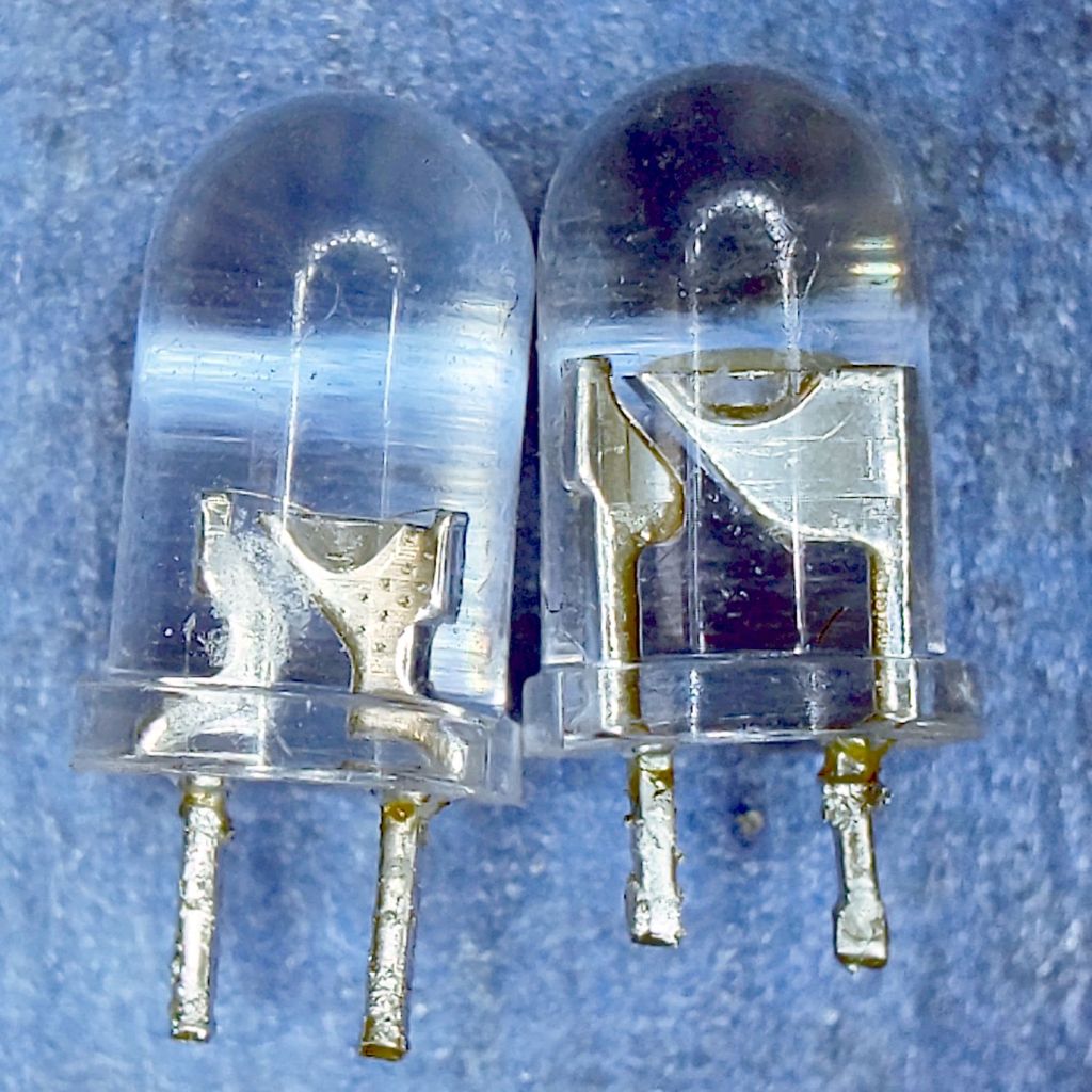
Pop quiz: which one of these LEDs caused the problem?
5 mm LEDs – swapped polarity
To the best of my knowledge, all 5 mm round LED packages mark the cathode lead with a flat edge. It’s easy to remember, as the cathode side of the schematic symbol has a bar: straight bar = straight edge.
Inside, the LED chip’s cathode lead is bonded to the reflective cup, with the anode lead wire-bonded to the top.
Took me a while to see what was wrong, too.
For whatever it’s worth, the backward LED works fine.
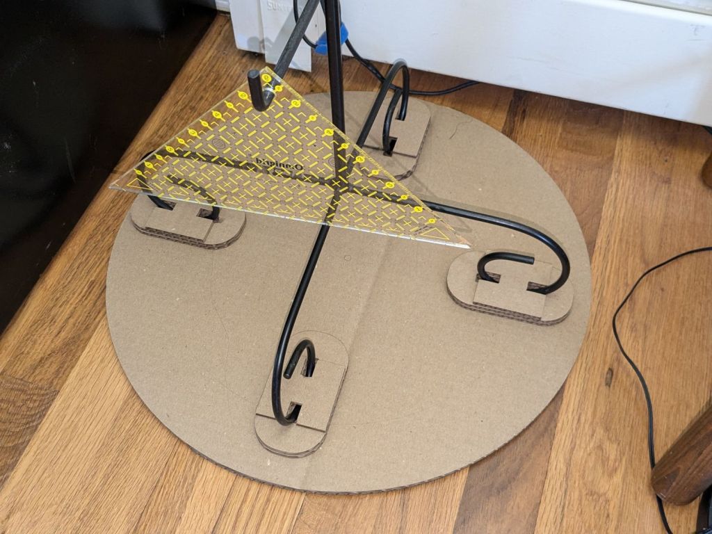
Mary is at least the third owner of a steel rack, originally intended to hold packages of retail stuff, which now holds (much of) her collection of quilting rulers:
Quilting Ruler Rack Base – overview
Obviously, it was never intended to hold heavy acrylic sheets, but it worked surprisingly well, right up to the point where too many of the rulers collected on two adjacent columns of pegs and overbalanced the whole affair atop her while she attempted to remove a ruler.
Subsequent accident recreation showed the rack toppled when the weight of the rulers on the two adjacent columns of hooks moved the center of mass outward, just inside the line between those feet, whereupon the slightest tug on a ruler pulled it over.
Measurements revealed the four legs do not sit on a square contact patch, are not parallel to the radii from the center point, and are not uniformly distant from the center. Rather than committing to a finished product, I made a cardboard prototype to verify a bigger base would solve the problem and I could capture all those feet.
You don’t have such a rack, so the exact dimensions don’t matter, but the LightBurn layout looks like this:
Quilting Ruler Rack Base
The disk is two cross-laid sheets for stiffness, with marks burned on the top to help align the feet more-or-less around the center point.
The oblong rings fit around the feet to capture them, so cut eight or twelve to make four stacks a bit taller than the wire diameter.
The H shape then glues atop the rings to hold the feet in place. They’re not removable, but a razor knife will eventually solve that problem.
I slobbered hot melt glue across the cardboard disks to hold them together, glued and aligned the rings where the feet dented the disks, stood the rack in the rings, and glued the H plates.
About an hour elapsed from the sound of the crash to the rack once again standing quietly beside the fabric cabinets.
We’ll run this for a while and eventually replace it with a plywood disk and screwed-in-place clamps for the feet, which will surely call for wood surface preparation / stain / seal treatment.
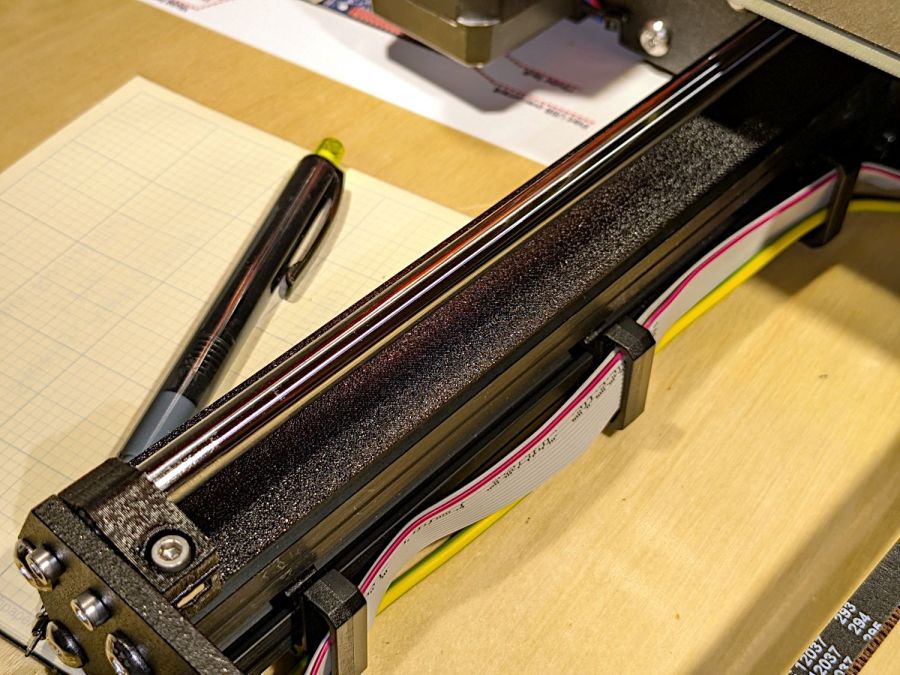
The Prusa belt tension guide pretty much explains that subject, with their Belt Tuner making up for my utter tone deafness. FWIW, if the Belt Tuner produces inconsistent results differing by an octave, either up or down from the correct value, the belt is way too loose: give the axis belt tension screw a turn or two to drag the results into the right time zone, then fine-tune from there.
While it is possible to reach both tensioning screws without too much trouble, they’re definitely not convenient.
The accelerometer fits on the hot end:
Prusa MK4 Accelerometer – on hot end
Then under the steel sheet, where it’s clamped by the platform magnets:
Prusa MK4 Accelerometer – on platform
The MK4 firmware measures the resonant frequencies while prompting you to put the accelerometer in the proper locations, then computes the best shaper values.
For reference, the stock OEM values:
X = MZV 50 Hz
Y = MZV 40 Hz
Just after I got the accelerometer and without doing anything to prep the MK4, these results popped out:
X = MZV 56 Hz
Y = MZV 42 Hz
Now, with bling and properly tensioned belts:
X = MZV 59 Hz
Y = MZV 45 Hz
The most recent values were also the most stable, once again pointing out the value of careful assembly and maintenance.
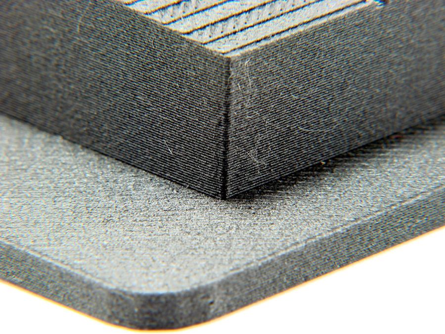
With that in mind, though, I built the laser ramp focus fixture shortly after doing the first recalibration and it has no visible ripples on any of its walls:
Ramp Test Fixture – corner detail
That’s a square corner perpendicular to the sloped top surface at the default 45 mm/s. It’s not as difficult a test as some you’ll see, but it suffices for my simple needs. The MK4 definitely behaves better around corners than the Makergear M2.
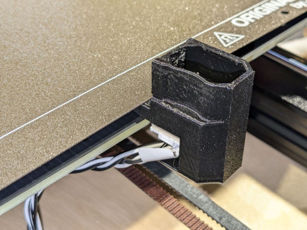
The small upward duct on the right side directs the exhaust air away from the platform. This is apparently critical for very high-temperature plastics like ABS and PC, but I did have one print fail due to excessively cold breezes on the platform.
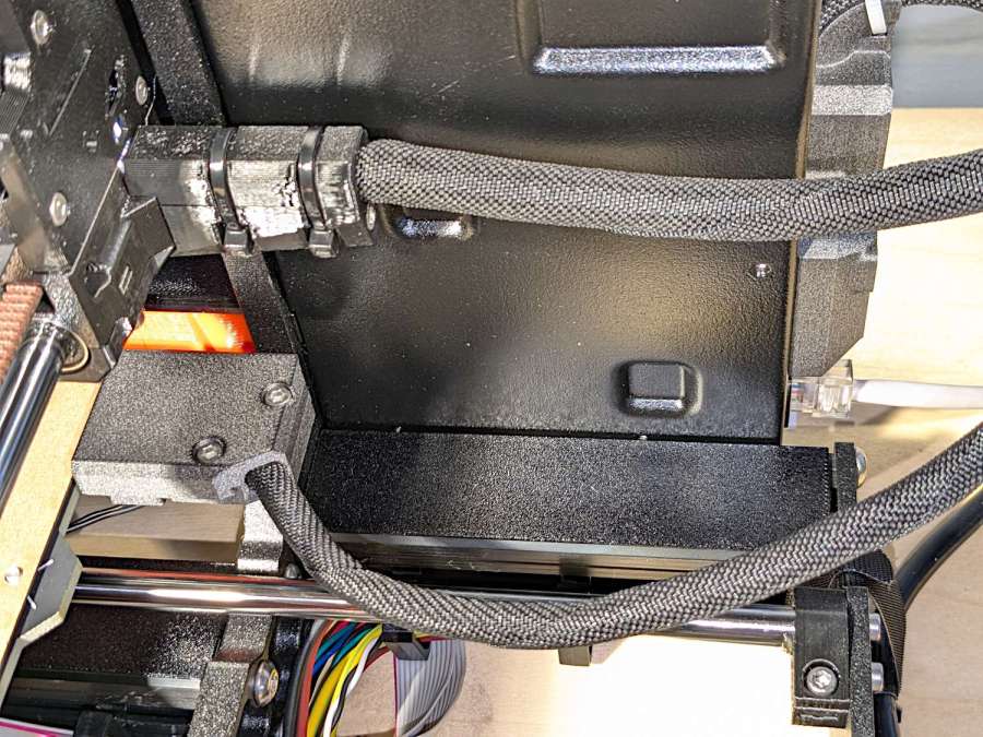
There’s also an angled heater cable connector cover, with a matching cover on the electronics box routing the cable rearward to dress it away from the hulking extruder cable:
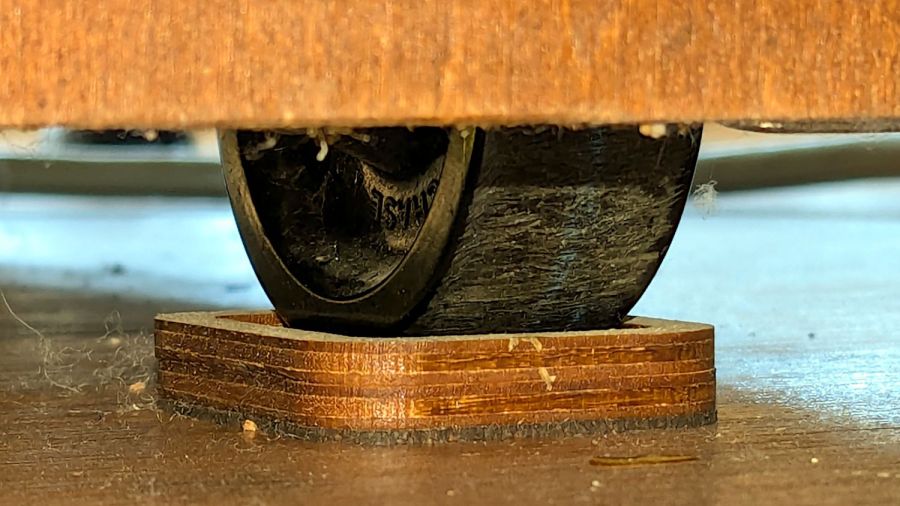
Mary’s much-improved / -repaired Sears Sewing Table wanted to move around on the wood floor in the Sewing Room, so I captured its casters in little pads:
Sears Sewing Table caster pad – installed
A layer of 1 mm cork with PSA adhesive provides griptivity against the floor, a solid layer of 3 mm plywood spreads the wheel force over the cork, and a top ring of 3 mm plywood captures the wheel.
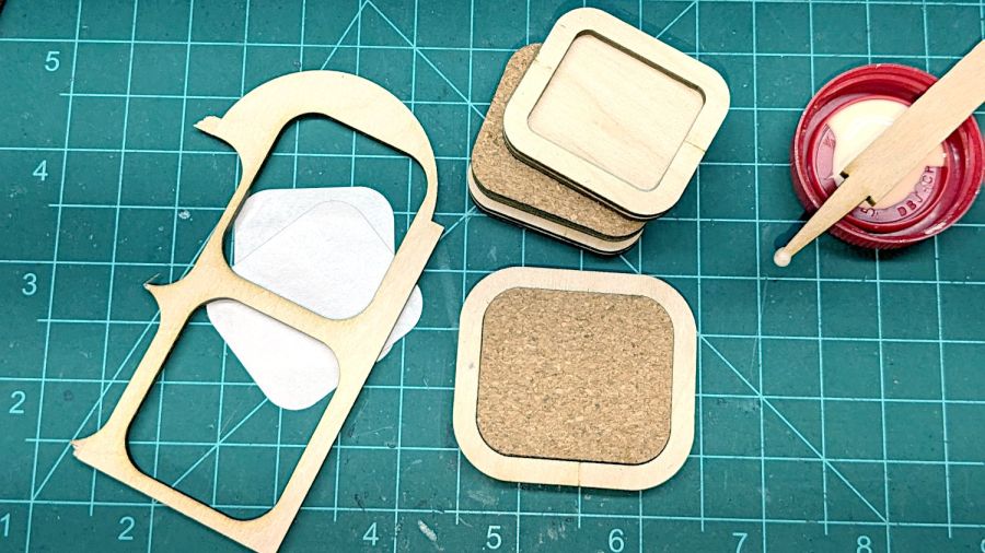
Which looked like this during gluing:
Sears Sewing Table caster pad – gluing fixtures
The scrap on the left served to align cork & plywood; it came from the plywood contributing the shapes. The ring around the cork is a glued-up pair of plywood rings (4 mm wide, outset from the perimeter of the pads) serving to align the two plywood layers.
Verily: time spent making a fixture is never wasted!
And having a laser cutter makes fixtures trivially easy, at least for simple fixtures like those.
Here’s what I think is going on, referring to the 4×8 foot (!) machine in that discussion and lightly edited to improve readability & fix minor errors …
Mirror 1 alignment gets the beam parallel to the Y axis, averaged over the gantry travel between front and rear. The path length variation on your machine is four feet.
Mirror 2 alignment gets the beam parallel to the X axis, averaged over the laser head travel from left to right. The path length variation on your machine is eight feet.
When the laser head is in the left rear corner, the total path length is maybe a foot or two. When it’s in the front right corner, the total path length is upwards of twelve feet.
The “Fourth Corner” problem comes from a slight angular misalignment of Mirror 1, because you (and I and everybody) must set it with a maximum path length around four feet (Mirror 1 to Mirror 2 with the gantry at the front end of the machine). But with the laser head in the right front corner, the path length (Mirror 1 to Mirror 3) is three times longer, so the error due to a slightly mis-set angle at Mirror 1 is correspondingly larger.
A tiny tweak to Mirror 1 changes the spot position at Mirror 2 by very little, but moves the spot at Mirror 3 by much more due to the longer path length.
Tweaking Mirror 1 cannot compensate for a warped machine frame, but it will get the beam alignment as good as it can be made.
The next point of contention was my “middle of the mirror” suggestion. AFAICT, the spot burned into the target at each mirror marks only the useful part of the beam with stray energy in a halo around it. Centering the spot keeps that stray energy away from the mirror mounts, so it doesn’t cause unnecessary heating. This will be particularly important with a high-power laser.
Angular adjustment of each mirror puts the beam parallel to the axes, but cannot also center it on the mirrors. After it’s aligned, the path from the laser tube through the nozzle depends on the position of the tube relative to the nozzle: moving the tube up/down and front/back moves the beam position on the mirrors and through the nozzle, but (in an ideal world) doesn’t change the angular alignment.
So after aligning the beam parallel to the axes, you must move the laser tube, the mirrors (up/down left/right front/back), and maybe the laser head to center the beam in the mirrors and also in the nozzle. Because we don’t live in an ideal world, moving any of those pieces wrecks their angular alignment, so it’s an iterative process.
The goal is to reach this point:
Beam Alignment – Mirror 3 detail – 2023-09-16
Those are five separate pulses, one each at the four corners and center of the platform.
The beam then goes pretty much through the center of the laser head and lens: