Ed Nisley's Blog: Shop notes, electronics, firmware, machinery, 3D printing, laser cuttery, and curiosities. Contents: 100% human thinking, 0% AI slop.
Tag: Improvements
Making the world a better place, one piece at a time
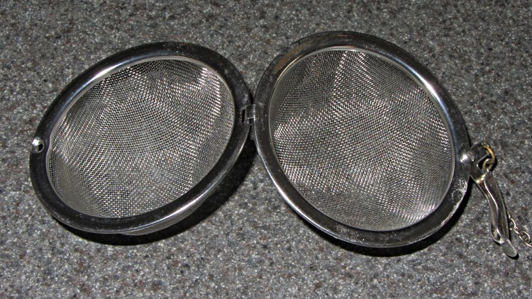
That tea ball (OK, infuser) hasn’t killed me yet, but it was looking rather grody despite a more-or-less monthly run through the dishwasher. So when Mary made up a bleach solution to sterilize her plant starting pots, I tossed it into the bottom of the pan for half an hour:
Bleached tea ball
Zowie! All the organic schmutz vanished, leaving it as good-looking as new.
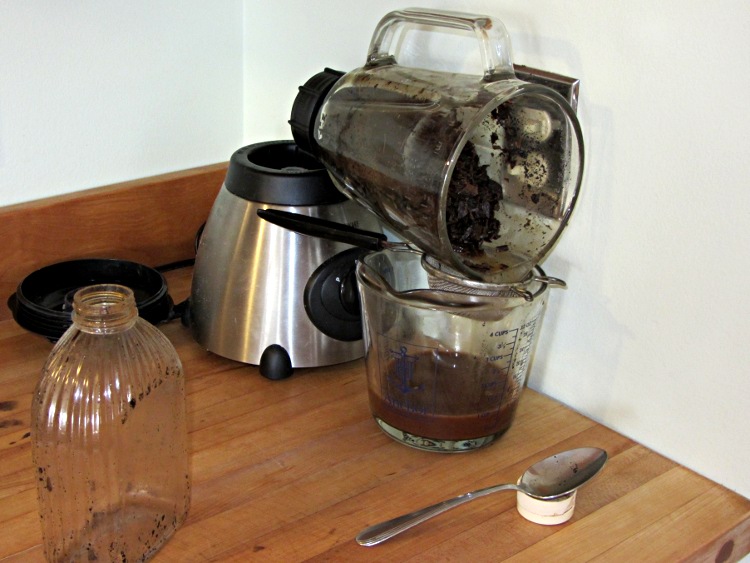
After decanting the homebrew vanilla extract from those bottles, I added enough vodka to cover the spent beans, ran them through the blender, and drained the liquid:
Draining the vanilla dregs
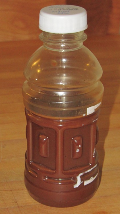
It’s rather muddy and probably not worth keeping, but we’ll see what settles out:
DIY Vanilla dregs
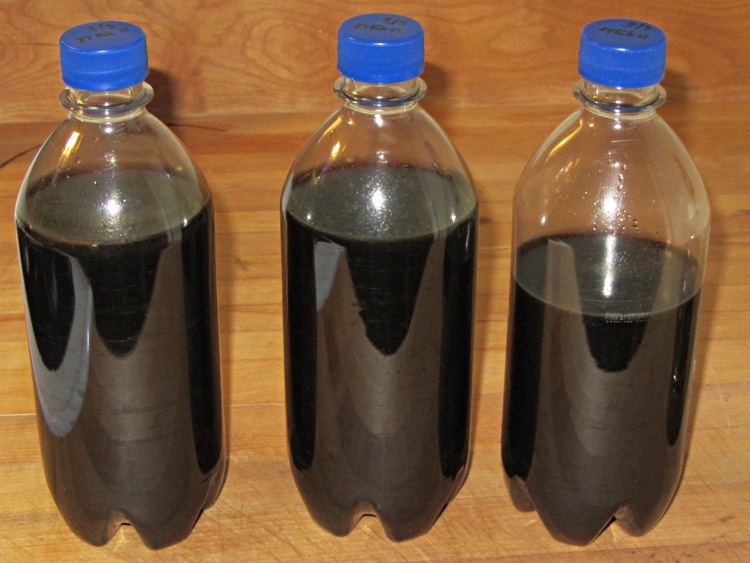
The Good Stuff looked like this before it went into a dark corner of the Basement Laboratory Storage Warehouse:
DIY Vanilla Extract – Batch 2 Done
It turns out you (well, I) cannot run vanilla extract through an ordinary coffee filter: it just doesn’t drain well at all. Cheesecloth didn’t seem worth the effort, so I combined all the clear liquid in a single jar, let it settle for a few days, then decanted it back into those three bottles again. The bottom of the rightmost bottle has a layer of what Breyers calls “real vanilla bean specks” in their ice cream.
In round numbers, $20 for half a pound of beans and $16 for a 1.75 l bottle of 80 proof vodka adds up to $36 for maybe 1.4 l of DIY vanilla extract = $26/l. Commercial vanilla extract runs about $72/l, so that’d be $100 in those bottles.
One could drive the DIY price down by processing more beans at a time, but this should keep us in vanilla for quite a while; that cup of hot cocoa in the afternoon smells really good now!
A week or so ago, the scroll ring on the Kensington Expert Mouse trackball at my left hand failed completely. Unlike the previousrepair attempts, tweaking the IR emitter-detector pair positions did nothing. Tried it on three different PCs and five different operating systems with the same result: the ring stayed dead.
Fortunately, this one was a warranty replacement for the dead Unit 1 I bought some years back and was still within its 5 year warranty, so when I contacted Kensington tech support with the story they immediately shipped a replacement. It just arrived and works fine.
The scroll ring detents seem much smoother on this one, so I haven’t taken it apart to remove the magnetic latch and don’t know if they’re using a different quadrature sensor. One can but hope.
Kensington Expert Mouse – ball bearing
For what it’s worth, an absolutely brand new ball barely moves on those three jeweled bearings (one marked with the yellow oval in the picture). Just rub the ball on one side of your nose to add some skin oil: shazam it spins like glass on ice.
They don’t mention that trick anywhere in the meager instructions…
Update: Eight years in the future, a real fix appears!
A few months after shaking off the previous fruit fly infestation, the worm compost bin has succumbed to another species of fruit fly that’s probably Drosophila melanogaster: much larger, breeds faster, and seems far more tenacious. Even though they’re completely innocuous, Something Must Be Done, but alas there are no insecticides suitable for a worm bin that produces vegetable garden compost. That reduces the situation to the Siege of Stalingrad: cut off their supplies and let them fight it out.
It seems that fruit flies and their progeny die slightly faster than worms; after three or six weeks without feeding, the flies will should be history and the worms will be eating the dead. Temperatures in the Basement Laboratory Vermiculture Wing will remain in the 60 °F range for the next month or two, so the fly egg-to-adult time will be longer than the usual eight days and this may not work as well as we’d like.
Assuming that succeeds, however, we’ll be freezing all the kitchen scraps that go into the bin to kill off the fruit fly eggs that arrive here from around the world. There seems no way to get fruits without fruit fly eggs, even with non-organic produce. Organic stuff, well, it’s worse than that.
I conjured up a Fruit Fly Escape trap that should I hope will lure flies out of the bin to their death, while keeping the worms inside.This won’t help much with the current extreme infestation, but may help dry the bin’s upper layer and, when we get the population knocked down, should exterminate the more adventurous survivors. Obviously, we’re breeding for stay-at-home fruit flies and, given their rapid-prototyping life cycle, they may evolve into tiny couch potatoes.
Anyhow.
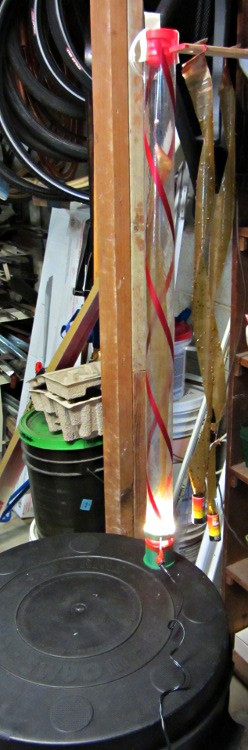
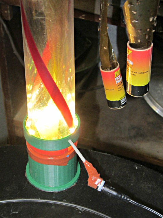
Flies like heat and light, while worms vastly prefer cool and dark, so the general idea is to drill a hole in the bin lid, fit a long tube over it, put an LED ring light at the base, and run a flypaper spiral up the tube to a vent cap near the top. The first picture gives an overview, although it’s tough to see the vertical tube against the clutter: it’s clear with two red spirals, having started life as some weird-ass holiday decoration for the previous owners of our house.
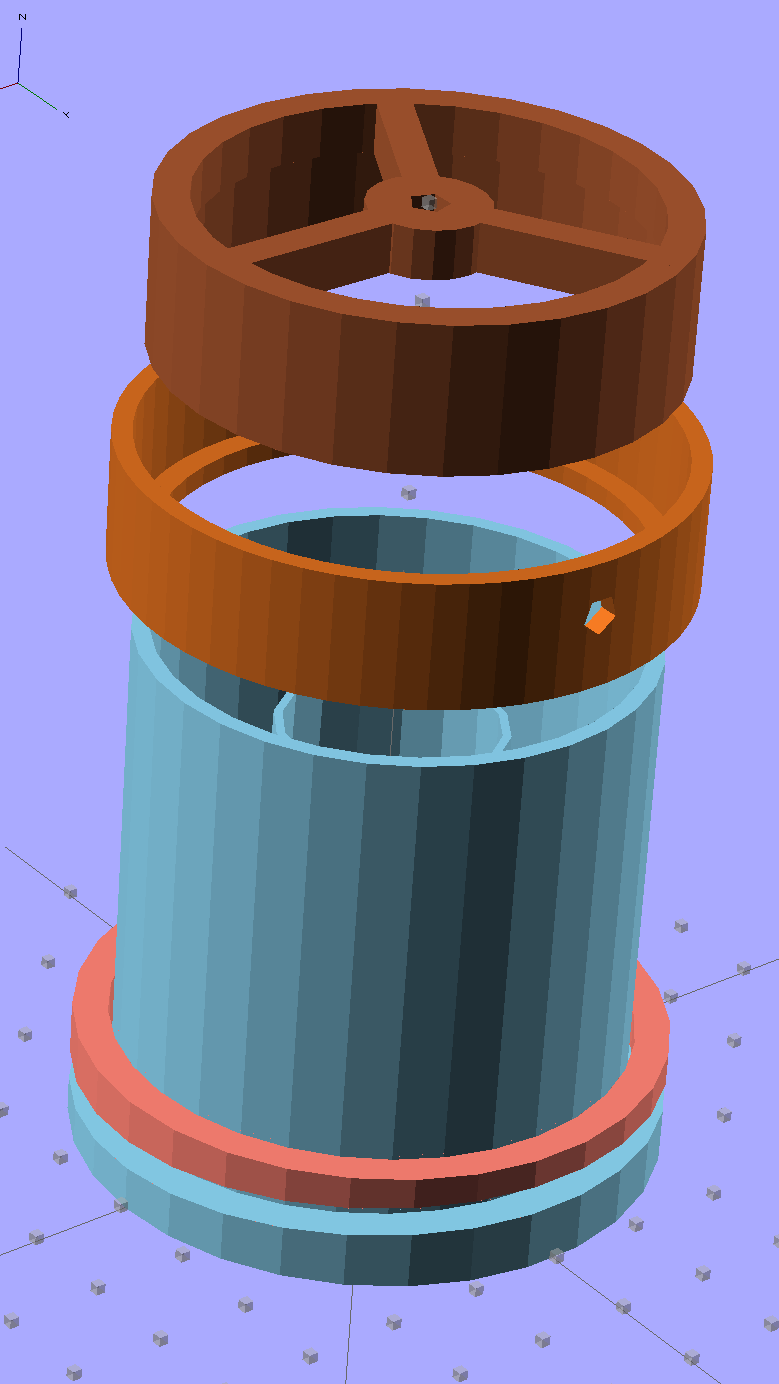
Anyhow, the more interesting plastic bits look like this:
Fly Escape – solid model
The top ring is the vent cap, with a hole in the middle for a string supporting the sticky tape strip. The middle ring holds three sections of LED strip light that dissipate about 2 W from a 12 V wall wart; that’s enough heat around the tube to produce a slight upward draft. The riser tube at the bottom has an angled rim that compensates for the bin lid angle and holds the long tube vertical. The ring around the riser has a matching angle.
They fit into the lid thusly:
Fly Escape – Riser trial fit
Two beads of hot-melt glue, top and bottom, hold them in place and make an air- / worm- / fly-tight seal.
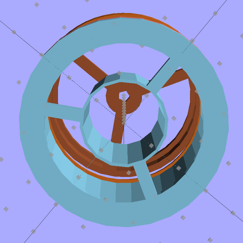
The inner tube holds the fly paper container and has a slight inward taper toward the top to wedge it in place:
Fly Escape – solid model – bottom
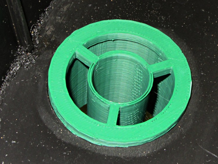
A similar view from inside the actual lid:
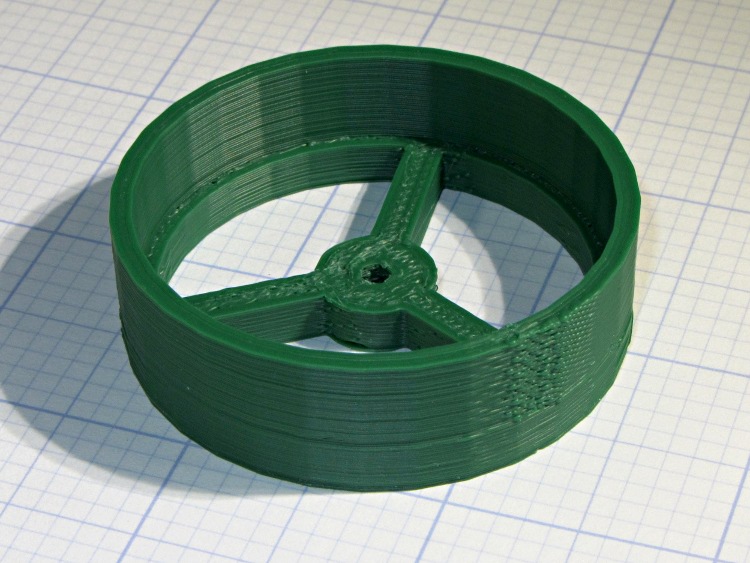
Fly Escape – Riser trial fit – bottom
That was the first pass at the dimensions; the tube walls didn’t quite join because I forgot to force the number of polygonal sides to be equal. It’s deliberately thin to make the walls springy, but everything must be Just Right to get both no fill and no space between the two perimeter threads.
The riser and LED ring, combined with festive spiral stripes along the tube and some silicone tape sealing the tubes together, produce a cheery nuclear glow that’s enhanced by the victims mired in the adjacent flypaper strips. A third strip runs up the middle of the tube:
Fly Escape in action
The vent cap on the top of the tube has a small hole in the middle to hold the string supporting the flypaper spiral exactly in the middle of the tube. This view is upside-down from the mounted orientation :
Fly Escape – Vent Cap
The alert reader will notice a red top plug in place of the vent cap in the first picture. This whole project happened over the course of a frantic afternoon, evening, and morning, with progressive product improvements along the way. For example, it turns out that some flies went pedestrian and walked up the inside of the tube, so there’s now a circle of screening inside that nice vented cap.
Having a 3D printer to hammer out custom plastic widgetry on a short schedule = win.
The OpenSCAD source code:
// Worm bin fly escape
// Ed Nisley KE4ZNU - March 2012

Layout = "Show";						// Build.. Show Riser Ring Cap

//- Extrusion parameters - must match reality!

ThreadThick = 0.25;
ThreadWidth = 2.0 * ThreadThick;

HoleFinagle = 0.3;
HoleFudge = 1.00;

function HoleAdjust(Diameter) = HoleFudge*Diameter + HoleFinagle;

Protrusion = 0.1;						// make holes end cleanly

//-- Dimensions

RiserID = 47.0;							// ID = transparent riser tube OD
RiserOD = 51.0;							// OD = hole in lid (matches hole saw OD)
RiserHeight = 50.0;						// wall height from lid

RiserSides = 4*8;						// for consistency & symmetry

RiserBaseHeight = IntegerMultiple(5.0,ThreadThick);			// stop ring height
RiserBaseID = RiserID - 2*1.0;								// stop ring ID

LipOD = 59.0;							// OD of lip mounted on lid around tube
LipAngle = 3.0;							// angle for lip to make tube vertical
LipMinThick = IntegerMultiple(3.0,ThreadThick);		// min lip thickness
LipAngleThick = LipOD*tan(LipAngle);				// angled section thickness
LipThick = LipMinThick + LipAngleThick;				// total lip thickness

RingClearance = 0.5;								// space between ring and tube

TrapID = 23.0;							// sticky tape container OD
TrapIDTaper = 2.0;						// taper to hold container in place
TrapHeight = 45.0;						//  ... height
TrapWallThickness = 2*ThreadWidth;
TrapSides = 4*4;

TrapFlanges = 3;						// number of support flanges
TrapFlangeThick = IntegerMultiple(3.5,ThreadWidth);

LEDThick = 2.5;							// LED strip thickness
LEDWidth = 11.0;						//  ... width
LEDWireOD = 3.0;						// power cable dia
LightID = RiserID + 2*LEDThick;			// ID of LED collar
LightOD = LightID + 2*4*ThreadWidth;		//  ... OD
LightFlangeThick = IntegerMultiple(2.0,ThreadThick);

CapID = RiserID;
CapRingID = CapID - 2*1.5;
CapOD = CapID + 2*4*ThreadWidth;
CapBaseHeight = RiserBaseHeight;
CapHeight = 10.0 + CapBaseHeight;
CapSides = RiserSides;
CapFlanges = 3;
CapFlangeThick = TrapFlangeThick;
CapGuideID = 3.0;
CapGuideOD = CapGuideID + 6*ThreadWidth;

//-- Sticky tape container holder

module TrapMount() {

  ODBot = TrapID + 2*TrapWallThickness;
  ODTop = TrapID - TrapIDTaper + 2*TrapWallThickness;

  difference() {
	union() {
	  cylinder(r1=ODBot/2,r2=ODTop/2,h=TrapHeight,$fn=TrapSides);
	  for (i=[0:TrapFlanges-1])
		rotate(i*(360/TrapFlanges) + 90)			// align leg with thick side
		  translate([RiserOD/4,0,RiserBaseHeight/2])
			cube([(RiserOD/2 - 4*Protrusion),TrapFlangeThick,RiserBaseHeight],center=true);
	}
	translate([0,0,-Protrusion])
	  cylinder(r1=HoleAdjust(TrapID)/2,
			   r2=HoleAdjust(TrapID - TrapIDTaper)/2,
			   h=(TrapHeight + 2*Protrusion),
			   $fn=TrapSides);
  }

}

//-- Riser tube

module RiserTube() {

  TotalHeight = RiserHeight + RiserBaseHeight;

  difference() {
	cylinder(r=RiserOD/2,h=TotalHeight,$fn=RiserSides);
	translate([0,0,RiserBaseHeight])
	  PolyCyl(RiserID,TotalHeight,RiserSides);
	translate([0,0,-Protrusion])
	  cylinder(r=RiserBaseID/2,h=TotalHeight,$fn=RiserSides);
  }

}

//-- Angled lip around ring
//		aligned with flat side downward at Z=0

module LipRing(Clearance = 0.0) {

  difference() {
	cylinder(r=LipOD/2,h=LipThick);
	translate([0,0,-Protrusion])
	  cylinder(r=(RiserOD/2 + Clearance),
			   h=(LipThick + 2*Protrusion),
			   $fn=RiserSides);
	rotate([LipAngle,0,0])
	  translate([-LipOD,-LipOD,(LipMinThick + LipOD/2*tan(LipAngle))])
		cube([2*LipOD,2*LipOD,LipAngleThick],center=false);
  }
}

//-- Collar to hold LED strip light

module LEDCollar() {

  difference() {
	PolyCyl(LightOD,(LEDWidth + LightFlangeThick));
	translate([0,0,LightFlangeThick])
	  PolyCyl(LightID,(LEDWidth + Protrusion));
	translate([0,0,-Protrusion])
	  PolyCyl(RiserID,(LightFlangeThick + 2*Protrusion));
	translate([0,0,(LightFlangeThick + LEDWidth/2)])
	  rotate([0,90,90])
		PolyCyl(LEDWireOD,LightOD);
  }
}

//-- Cap to hold trap string and vent the tube

module VentCap() {

	union() {
	  difference() {
		cylinder(r=CapOD/2,h=CapHeight,$fn=CapSides);
		translate([0,0,-Protrusion])
		  cylinder(r=CapRingID/2,h=(CapHeight +2*Protrusion),$fn=CapSides);
		translate([0,0,CapBaseHeight])
		  cylinder(r=CapID/2,h=CapHeight,$fn=CapSides);
	  }
	  difference() {
		union() {
		  for (i=[0:TrapFlanges-1])
			rotate(i*(360/CapFlanges))
			  translate([CapOD/4,0,CapBaseHeight/2])
				cube([(CapOD/2 - 4*Protrusion),CapFlangeThick,CapBaseHeight],center=true);
		  cylinder(r=CapGuideOD,h=CapBaseHeight);
		}
		translate([0,0,-Protrusion])
		  PolyCyl(CapGuideID,CapHeight);
	  }
	}

}

//-- Handy routines

function IntegerMultiple(Size,Unit) = Unit * ceil(Size / Unit);

module PolyCyl(Dia,Height,ForceSides=0) {           // based on nophead's polyholes

  Sides = (ForceSides != 0) ? ForceSides : (ceil(Dia) + 2);

  FixDia = Dia / cos(180/Sides);

  cylinder(r=(FixDia + HoleFinagle)/2,h=Height,$fn=Sides);
}

//-- Put peg grid on build surface

module ShowPegGrid(Space = 10.0,Size = 1.0) {

  Range = floor(50 / Space);

	for (x=[-Range:Range])
	  for (y=[-Range:Range])
		translate([x*Space,y*Space,Size/2])
		  %cube(Size,center=true);

	for (z=[1:10])
	  translate([0,0,z*Space])
		  %cube(Size,center=true);
}

//- Build it

ShowPegGrid();

if (Layout == "Ring")
  LipRing();

if (Layout == "Riser")
  RiserTube();

if (Layout == "Cap")
  VentCap();

if (Layout == "Show") {
  color("SkyBlue") {
	TrapMount();
	RiserTube();
	LipRing();
  }
  color("Salmon")
	translate([0,0,2*LipThick])
	  rotate([180,0,0])
		LipRing(RingClearance);
  color("Chocolate")
	translate([0,0,(1.25*RiserHeight)])
	  LEDCollar();
  color("Sienna")
	translate([0,0,2*RiserHeight])
	  rotate([180,0,0])
		VentCap();
}

if (Layout == "Build1") {
  TrapMount();
  RiserTube();
  LipRing();
}

if (Layout == "Build2") {
	LipRing(RingClearance);
}

if (Layout == "Build3") {
	LEDCollar();
}

if (Layout == "Build4") {
	VentCap();
}
That’s a 33 uF 300 V electrolytic that started life as a surface-mount kludge, simply soldered to the Peltier supply’s screw terminal pins on the bottom of the board.
With the cap in place, the supply drops to 4 V at turn-on and bumps to 6 V at turn-off, with the transients much better-behaved now.
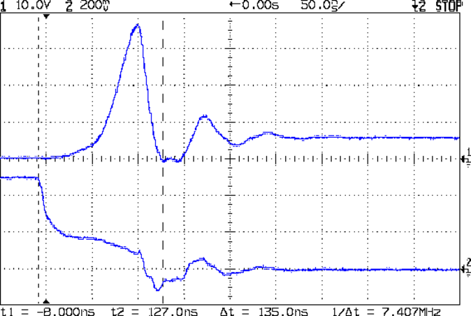
Those spikes at the turn-off transient are also somewhat better, even if the MOSFET drain rings for another cycle before dying out. The peak is down to 35 V, which I think comes from the other end of the circuit being more reluctant to instantly jump 70 V, and the width has decreased, too:
Peltier Drain Ringing – 30 uF Supply
The ringing jumped to 15 MHz, rather than 5 MHz, which means it’s over faster even if there’s another cycle. If it were any worse, I’d be forced to re-figure the snubber RC numbers…
The Miller capacitance effect still shows up clearly on the gate drive in the lower trace. There’s a reason why you really need higher-performance drivers for faster circuits!
It appears there are at least two different 10 W aluminum resistor sizes: the one used by Dale and the one used by everybody else. It’s either that or the EAGLE HS10 symbol is wrong…
Using those dimensions, here’s a part that more closely fits the resistors in my heap. EAGLE 6 uses an XML file format, so you can stuff some ASCII text into the appropriate sections of your custom.lbr file (or whatever).
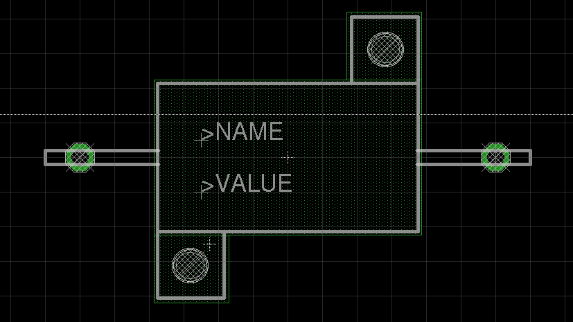
The EAGLE package, which remains HS10 as in the resistor-power library, should produce something that looks like this:
EAGLE 10 W Resistor package
The XML code includes top-keepout rectangles under the body footprint:
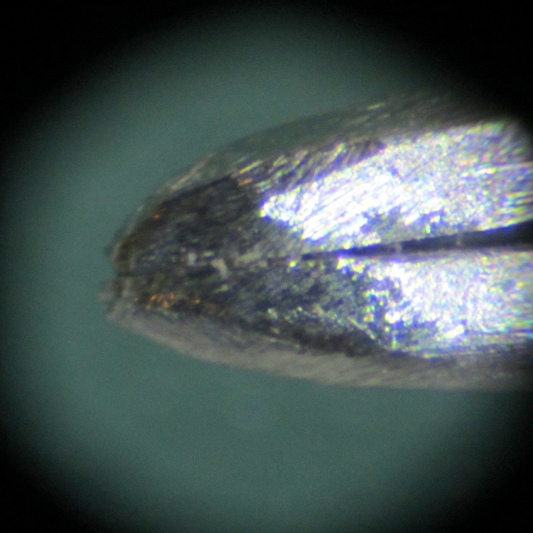
During a recent rainstorm I grabbed the fiberglass marker pole at the end of the drain pipe to clear a wad of leaves out of the driveway gutters. Unfortunately, that left me with a finger full of glass fibers; it seems the top of the pole has deteriorated. The first tweezer I plucked from the stash around the pencil-oid tool holder hadn’t had its jaws aligned, so after I plucked (most of) the glass using those tweezers, I did a bit of filing and sandpapering:
Tweezer tips
That’s a millimeter scale in the background: these really are needle-tip tweezers.
A closer view:
Aligned and shaped tweezer tip
It still has a bit of overbite, but it grabs hairs from the bench with no hassle. Given that you can’t get all the glass fibers on the first pass, it’ll come in handy…