The Smell of Molten Projects in the Morning

Ed Nisley's Blog: Shop notes, electronics, firmware, machinery, 3D printing, laser cuttery, and curiosities. Contents: 100% human thinking, 0% AI slop.

Tag: Improvements

Making the world a better place, one piece at a time

  • Drilling a Drainage Hole in a Plant Pot

    We divided an ancient Snake (a.k.a. Mother-In-Law’s Tongue) Plant and discovered the pot had no drainage hole, which is not to be tolerated.

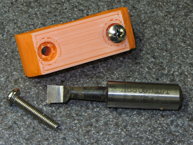
    It turns out that an ordinary carbide glass drill works just fine on glazed clay pots. Use a low RPM and very slow feed, flood the scene with water, and drill from the other side after the point breaks through.

    Glass drill for plant pot hole
    Glass drill for plant pot hole

    The glaze inside the pot already had a flaw that let the water into the clay, from whence it seeped out through the unglazed lower rim. I suppose saturating the clay can’t possibly be good, but I’ve done this to many glazed pots over the years and none of them have ever complained, so it’s all good.

  • Helmet Mirror: Smaller Mirror Shaft

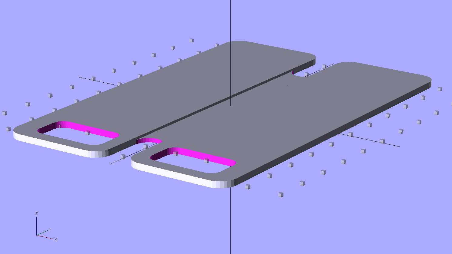
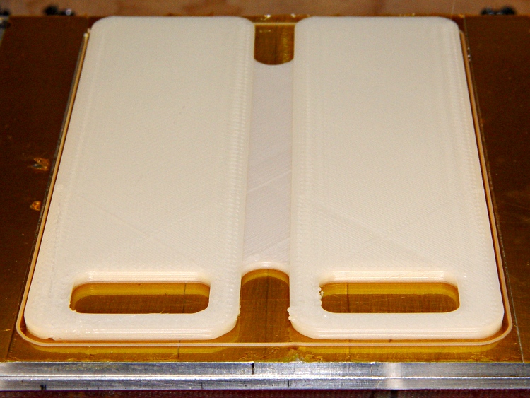
    This is the slightly smaller mount corresponding to the OpenSCAD code there for the two-section inspection mirror shaft, hot from the printer:

    Helmet mirror mount on build platform - smaller mirror shaft
    Helmet mirror mount on build platform – smaller mirror shaft

    It’s about the same as the previous version, despite trimming a few millimeters from the diameters and spacings:

    Helmet mirror mount size comparison
    Helmet mirror mount size comparison

    I’ll print the next one in a darker color. At least it’s not pink…

    The OpenSCAD source:

    // Helmet mirror mount
    // Ed Nisley KE4ZNU June 2011
    
    include </home/ed/Thing-O-Matic/lib/MCAD/units.scad>
    include </home/ed/Thing-O-Matic/lib/MCAD/boxes.scad>
    include </home/ed/Thing-O-Matic/lib/visibone_colors.scad>
    
    //-- Layout Control
    
    Layout = "Build";					// Build Fit Show None
    
    Examine = "None";				// AzMount ElMount ElBody ElPlate HelmetPlate None
    
    //-- Extrusion parameters
    
    ThreadThick = 0.33;
    ThreadWT = 2.0;
    ThreadWidth = ThreadThick * ThreadWT;
    
    HoleWindage = 0;			// enlarge hole dia by this amount
    
    //-- Useful sizes
    
    Tap2_56 = 0.070 * inch;
    Clear2_56 = 0.082 * inch;
    Head2_56 = 0.156 * inch;
    Head2_56Thick = 0.055 * inch;
    Nut2_56Dia = 0.204 * inch;
    Nut2_56Thick = 0.065 * inch;
    
    Tap3_48 = 0.079 * inch;
    Clear3_48 = 0.096 * inch;
    Head3_48 = 0.184 * inch;
    Head3_48Thick = 0.058 * inch;
    Nut3_48Dia = 0.201 * inch;
    Nut3_48Thick = 0.073 * inch;
    
    Tap4_40 = 0.089 * inch;
    Clear4_40 = 0.110 * inch;
    Head4_40 = 0.211 * inch;
    Head4_40Thick = 0.065 * inch;
    Nut4_40Dia = 0.228 * inch;
    Nut4_40Thick = 0.086 * inch;
    
    //-- Azimuth Mount
    
    AzMountDia = 12.0;
    AzMountLength = 14.0;
    
    AzFacets = 30;
    
    echo(str("Azmuth mount dia: ",AzMountDia," length: ",AzMountLength));
    
    //-- Mirror sizes
    
    MirrorShaftDia = 3.60;
    MirrorShaftOffset = -1.5;				// vertical offset from center of AzMountBody
    MirrorShoulderLen = 3*MirrorShaftDia;
    MirrorShoulderDia = min(AzMountDia,MirrorShaftDia + 6*ThreadWidth);
    
    MirrorStudDia = Tap3_48;
    MirrorStudLen = 2.0;
    
    //-- Elevation Mount / Body / Plate
    
    ElMountDia = AzMountDia;
    ElMountLength = 2.0 + ElMountDia;
    
    ElMountBase = 2.0;
    
    ElMountRounding = 2.0;
    
    ElMountFacets = AzFacets;
    
    ElBodyWidth = ElMountDia;
    ElBodyBlockLength = ElMountLength + AzMountLength/2 - MirrorShaftOffset;
    ElBodyThick = 8.0;
    
    echo(str("Elevation body overall: ",(ElBodyBlockLength + ElBodyWidth/2)," width: ",ElBodyWidth));
    
    ElPlateTall = ElBodyBlockLength + 0.70*ElBodyWidth;
    ElPlateWidth = 1.25 * ElPlateTall;
    ElPlateThick = Nut3_48Thick + 3*ThreadThick;
    
    ElPlatePlusX = ElPlateThick + (ElMountDia/2 + ElMountBase) + ElBodyThick;
    
    echo(str("Elevation plate tall: ",ElPlateTall," width: ",ElPlateWidth));
    
    ElArcRadius = (3/4) * ElBodyBlockLength;
    ElArcThick = 4*ThreadWidth;
    ElArcHeight = (1/2) * ElBodyThick;
    ElArcAngle = 35;
    ElArcFacets = 32;
    
    ElPlateFacets = 52;
    
    //-- Helmet Interface Plate
    
    HelmetCX = 60.0;
    HelmetMX = 4.0;
    HelmetRX = (pow(HelmetMX,2) + pow(HelmetCX,2)/4)/(2*HelmetMX);
    
    HelmetPlateC = max(ElPlateTall,ElPlateWidth);
    HelmetPlateTheta = atan(HelmetPlateC/HelmetRX);
    HelmetPlateM = 2*HelmetRX*pow(sin(HelmetPlateTheta/4),2);
    
    HelmetPlateThick = ThreadThick*(ceil(HelmetPlateM/ThreadThick) + 1);
    
    //-- Bearing Interfaces
    
    BearingWidth = 3*ThreadWidth;
    
    BearingOverlap = 3*ThreadThick;
    BearingClearance = 1*ThreadThick;
    
    BearingStudDia = min(AzMountDia,ElBodyWidth) - 2*BearingWidth;
    
    //-- Convenience values
    
    Protrusion = 0.1;		// make holes look good
    
    //----------------------
    // Useful routines
    
    module PolyCyl(Dia,Height) {			// based on nophead's polyholes
    
      Sides = ceil(Dia) + 2;
      FixDia = Dia / cos(180/Sides);
    
      cylinder(r=(FixDia + HoleWindage)/2,
               h=Height,
    	   $fn=Sides);
    }
    
    PegSize = 1.0;
    
    module ShowPegGrid(Size) {
    	for (x=[-5:5])
    	  for (y=[-5:5])
    		translate([x*10,y*10,Size/2])
    		  cube(Size,center=true);
    
    }
    
    //----------------------
    // Azimuth Mount
    
    module AzMount() {
    
      difference() {
    	union() {
    	  cylinder(r=AzMountDia/2,h=AzMountLength,$fn=AzFacets);		// body
    	  translate([0,0,AzMountLength/2 + MirrorShaftOffset])
    		rotate([-90,0,0])
    		  cylinder(r=MirrorShoulderDia/2,
    				   h=MirrorShoulderLen,$fn=AzFacets);				// mirror shaft shoulder
    
    	  if (Layout != "Fit")
    		for (y=[0:1])												// shoulder support
    		  translate([-AzMountDia/2,(4*y + AzMountDia/2 + ThreadWidth),0])
    			difference() {
    			  cube([AzMountDia,2*ThreadWidth,AzMountLength/6]);
    			  translate([AzMountDia/2,-Protrusion,AzMountLength/2 + MirrorShaftOffset])
    				rotate([-90,0,0])
    				  cylinder(r=MirrorShoulderDia/2,h=ThreadWidth + 2*Protrusion);
    			}
    	}
    
        translate([0,-Head3_48/2,AzMountLength/2 + MirrorShaftOffset])
          rotate([-90,0,0])
    		PolyCyl(MirrorShaftDia,(AzMountDia + MirrorShoulderLen));	// mirror shaft
    
        translate([0,-(Head3_48/2 - Protrusion),AzMountLength/2 + MirrorShaftOffset])
    	  rotate([90,0,0])
    		PolyCyl(MirrorStudDia,MirrorStudLen+Protrusion);			// mirror stud
    
        translate([0,0,
    	       Head3_48Thick - (AzMountLength - MirrorShaftDia)/2 + MirrorShaftOffset - Protrusion])
          PolyCyl(Head3_48,AzMountLength + Protrusion);					// mounting screw head
    
        translate([0,0,-Protrusion])
          cylinder(r=(Clear3_48 + HoleWindage)/2,
    	  h=(AzMountLength + 2*Protrusion),
    	  $fn=ceil(Clear3_48)+2);										// mounting screw clearance
    
    	translate([0,0,AzMountLength/2 + Head3_48Thick + MirrorShaftDia/2 + MirrorShaftOffset - Protrusion])
    	  cylinder(r1=(Head3_48/cos(180/7) + HoleWindage)/2,
    			   r2=Clear3_48/2,
    			   h=(3*ThreadThick + Protrusion),
    			   $fn=7);												// overhang support
    
        translate([0,0,AzMountLength/2 + MirrorShaftOffset])
          rotate([0,90,0])
    		PolyCyl(Tap2_56,AzMountDia/2 + Protrusion);					// setscrew hole
    
        translate([0,0,AzMountLength - (BearingOverlap + BearingClearance)])
    	  PolyCyl(BearingStudDia,
    			  BearingOverlap + BearingClearance + Protrusion);		// bearing surface
    
      }
    
    }
    
    //----------------------
    // Elevation Mount
    
    module ElMount() {
    
      difference() {
    
    	union() {
    
    	  translate([(ElMountDia/4 + ElMountBase/2),0,(ElMountLength/2 + BearingOverlap)])
    		rotate([0,90,0])
    		  cube([ElMountLength,ElMountDia,(ElMountDia/2 + ElMountBase)],
    			  center=true);											// mounting block
    
    	  translate([0,0,BearingOverlap]) {
    //		color([0.4,0.3,0.3,0.7])
    		cylinder(r=ElMountDia/2,
    				 h=ElMountLength - ElMountDia/2,
    				 $fn=ElMountFacets);								// cylinder to Az
    
    //		color([0.3,0.4,0.3,0.7])
    		translate([0,0,ElMountLength - ElMountDia/2]) {				// curved interface
    		  intersection() {
    			cylinder(r=ElMountDia/2,h=ElMountDia/2,$fn=ElMountFacets);
    			translate([0,ElMountDia/2,0])
    			  rotate([90,0,0])
    				cylinder(r=ElMountDia/2,h=ElMountDia,$fn=ElMountFacets);
    		  }
    		}
    
    	  }
    
    	  cylinder(r=(BearingStudDia - HoleWindage)/2,h=BearingOverlap);	// bearing stud
    	}
    
    	translate([0,0,-Protrusion])
    	  PolyCyl(Tap3_48,(3/4)*ElMountLength + BearingOverlap + Protrusion);	// AzMount screw
      }
    }
    
    //----------------------
    // Elevation Body
    
    module ElBody() {
    
      difference() {
    	union() {
    	  translate([-ElBodyBlockLength,-ElBodyWidth/2,0])
    		cube([ElBodyBlockLength,ElBodyWidth,ElBodyThick]);
    	  translate([0,0,ElBodyThick])
    		cylinder(r=(ElBodyWidth - 2*BearingWidth)/2,h=BearingOverlap);
    	  cylinder(r=ElBodyWidth/2,h=ElBodyThick,$fn=ElMountFacets);
    	}
    
    	PolyCyl(Clear3_48,ElBodyThick + BearingOverlap + Protrusion);
    
    	translate([0,0,-Protrusion])
    	  PolyCyl(Head3_48,Head3_48Thick);
    
    	translate([-ElArcRadius,0,ElBodyThick - ElArcHeight/2])
    	  rotate([0,-90,0])
    		PolyCyl(Tap2_56,ElBodyBlockLength - ElArcRadius + Protrusion);
    
    	translate([0,0,ElBodyThick - (ElArcHeight + BearingClearance)])
    	  difference() {
    		cylinder(r=ElArcRadius + (ElArcThick/2 + BearingClearance),
    				 h=ElArcHeight + BearingClearance + Protrusion,
    				 $fn=ElArcFacets);
    		cylinder(r=ElArcRadius - (ElArcThick/2 + BearingClearance),
    				 h=ElArcHeight + BearingClearance + Protrusion,
    				 $fn=ElArcFacets);
    	  }
    
      }
    
    }
    
    //----------------------
    // Elevation Plate
    
    module ElPlate() {
    
      union() {
    	difference() {
    	  translate([ElBodyWidth/2 - ElPlateTall/2,0,0])
    		scale([ElPlateTall,ElPlateWidth,1.0])
    		  cylinder(r=0.5,h=ElPlateThick,$fn=ElPlateFacets);
    	  translate([0,0,-Protrusion])
    		PolyCyl(Tap3_48,ElPlateThick + 2*Protrusion);
    	  translate([0,0,ElPlateThick - (BearingOverlap + BearingClearance)])
    		PolyCyl(BearingStudDia,(BearingOverlap + BearingClearance) + Protrusion);
    	  translate([0,0,-Protrusion])
    		cylinder(r=Nut3_48Dia/2,h=(1.1*Nut3_48Thick + Protrusion),$fn=6);
    	}
    
    	translate([0,0,ElPlateThick])
    	difference() {
    	  cylinder(r=ElArcRadius + ElArcThick/2,
    			   h=ElArcHeight,
    			   $fn=ElArcFacets);
    	  cylinder(r=ElArcRadius - ElArcThick/2,
    			   h=ElArcHeight + Protrusion,
    			   $fn=ElArcFacets);
    	  rotate([0,0,90 - ElArcAngle])
    	    translate([ElArcRadius + ElArcThick,0,ElArcHeight/2])
    		  cube([2*ElArcRadius + ElArcThick,
    				2*ElArcRadius + ElArcThick,
    				ElArcHeight + Protrusion],
    				center=true);
    	  rotate([0,0,-(90 - ElArcAngle)])
    	    translate([ElArcRadius + ElArcThick,0,ElArcHeight/2])
    		  cube([2*ElArcRadius + ElArcThick,
    				2*ElArcRadius + ElArcThick,
    				ElArcHeight + Protrusion],
    				center=true);
    	}
      }
    }
    
    //----------------------
    // Helmet Interface Plate
    
    module HelmetPlate() {
    
      difference() {
    	scale([ElPlateTall,ElPlateWidth,1.0])
    	  cylinder(r=0.5,h=HelmetPlateThick,$fn=ElPlateFacets);
    
    	translate([0,0,HelmetRX + HelmetPlateThick - HelmetPlateM])
    	  sphere(r=HelmetRX,$fn=256,$fs=0.1);
    
      }
    }
    
    //----------------------
    // Lash it together
    
    if (Examine == "AzMount")
      AzMount();
    
    if (Examine == "ElMount")
      ElMount();
    
    if (Examine == "ElBody")
      ElBody();
    
    if (Examine == "ElPlate")
      ElPlate();
    
    if (Examine == "HelmetPlate")
      HelmetPlate();
    
    if ((Layout == "Build" || Layout == "Show") && Examine == "None") {
      translate([-10,-20,0])
    	rotate([0,0,90])					// mis-align top fill from ElMount
    	  AzMount();
    
      translate([-10,20,ElMountLength + BearingOverlap])
    	rotate([0,180,-90])
    	  ElMount();
    
      translate([0,0,0])
    	rotate([0,0,0])
    	  ElBody();
    
      translate([10,15,0])
    	rotate([0,0,215])					// mis-align top fill from ElBody
    	  ElPlate();
    
      translate([20,-20,0])
    	rotate([0,0,-45])
    	  HelmetPlate();
    
      if (Layout == "Show")
    	ShowPegGrid(PegSize);
    
    }
    
    if ((Layout == "Fit") && Examine == "None") {
      translate([0,0,-(AzMountLength/2 + MirrorShaftOffset)])
    	color(MFG) AzMount();
    
      translate([0,0,AzMountLength/2 - MirrorShaftOffset - BearingOverlap])
    	color(DHC) ElMount();
    //	color([  0/255, 204/255, 204/255,0.5]) ElMount();
    
    	translate([ElMountDia/2 + ElMountBase,0,0])
    	  rotate([0,90,0])
    		color(DFC) ElBody();
    
    	translate([ElPlatePlusX,0,0])
    	  rotate([180,90,0])
    		color(LHC) ElPlate();
    
    	translate([ElPlatePlusX,0,ElPlateTall/2 - ElBodyWidth/2])
    	  rotate([0,90,0])
    		color(LWM) HelmetPlate();
    }
    
  • Lawn Mower Drive Control Lever Assist

    Our Craftsman lawn mower has both a deadman grip for the motor (the Operator Presence Control Bar) and a Drive Control Lever that engages the rear wheel drive. The latter requires a death grip to keep the belt engaged, which means you (well, I) spend about two hours clenching the grip.

    Lawn mower - compound leverage handle
    Lawn mower – compound leverage handle

    I’ve long since flipped the control to the left side and added thick foam padding, but there’s no adjustment that reduces the death-grip requirement: you can change the engagement distance, not the spring constant.

    Evidently the Sears engineers have much stronger hands than anyone in our family.

    The doodad hose-clamped to the upright part of the mower handle is a basically a hinge that applies force to the tip of the red handle. The hinge axis lies far enough from the handle’s pivot so that holding the hinge against the handle requires very little force; at least it’s no longer a death grip.

    Lawn mower - compound leverage handle engaged
    Lawn mower – compound leverage handle engaged

    It’s not an ideal solution, but it engages and (more importantly) disengages easily. I still don’t like mowing the lawn, but at least I don’t return with a crippled-up hand.

    The hinge is actually a lock hasp, so it has a slot that slides neatly over the Drive Control Lever’s tab. I beat both sides into a more-or-less cylindrical form over a piece of pipe, while miraculously not bending the hinge pin.

    Evidently the Sears engineers never actually used the damn mower for two hours at a time.

  • Thing-O-Matic: Fairing Clamp Plates

    Although those pink clamp plates worked well enough, they did not provide, shall we say, a completely satisfactory user experience. I reprinted new sets in red while varying the extruder speed by 0.1 rev/min, with small tweaks to the overlap between the infill and the loop threads.

    First, the big pictures with details scrawled on the back of the lower plate…

    At 3.2 rpm, which is only slightly too fast:

    Fairing Plate - 3.2 rpm
    Fairing Plate – 3.2 rpm

    At 3.3 rpm, a bit overstuffed:

    Fairing Plate - 3.3 rpm
    Fairing Plate – 3.3 rpm

    At 3.4 rpm, there’s obviously too much plastic:

    Fairing Plate - 3.4 rpm
    Fairing Plate – 3.4 rpm

    Some closeups, in the same order…

    At 3.2 rpm with 0.20 overlap, it looks OK:

    Fairing Plate - 3.2 rpm detail
    Fairing Plate – 3.2 rpm detail

    At 3.3 rpm with 0.25 overlap, which pretty much devours the inner loop thread:

    Fairing Plate - 3.3 rpm detail
    Fairing Plate – 3.3 rpm detail

    At 3.4 rpm with 0.25 overlap there’s serious overfill:

    Fairing Plate - 3.4 rpm detail
    Fairing Plate – 3.4 rpm detail

    In all cases, the extruder left a track while exiting upward from near the middle of the images. Even at 3. 2 rpm there’s slightly too much plastic.

    My ladies don’t care about the fine details. They prefer red to pink and the clamps hold the fairings firmly in place…

  • Thing-O-Matic: LED Lighting Upgrade

    Another one of those LED ring lights wound up in the Thing-O-Matic, affixed to the underside of the Z stage with double-sticky foam tape. You can see the whole ring reflected in that picture, but the front third of the ring obscured what the nozzle was doing.

    So I sawed out one of the three-LED strings to open a gap:

    LED ring light with gap
    LED ring light with gap

    Unfortunately, the designers arranged things so that the ballast resistor for each string sits directly above the last LED of the adjacent string. The white wire you can barely see connects the ballast resistor that drove the now-missing string on the left to the via feeding the first string on the right.

    It now fits around the extruder with the gap exactly matching the opening in front of the Thermal Core.

    LED ring light installed
    LED ring light installed

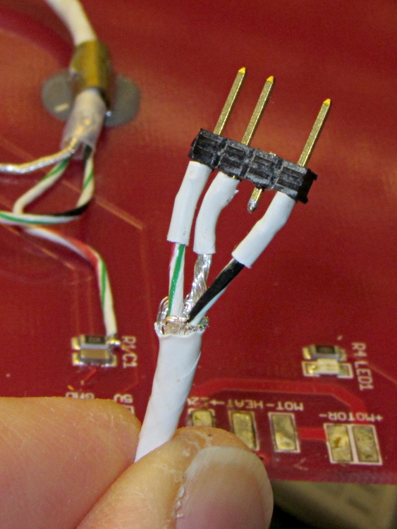
    Power comes from a screw terminal connector I hacked into the 4-pin block that used to be part of the 20+4-pin ATX power block at the Motherboard. There’s a length of overly stout 4-wire cable leading to a kludged not-a-connector made of square pins and heatshrink tubing jammed into the block.

    TOM auxiliary power connector
    TOM auxiliary power connector

    It provides +12, +5, +3.3 V, and ground for the fan and LED lighting.

    Most of the light in that last picture comes from LED strips on either side of the front opening. My Shop Assistant won a meter of warm-white LEDs at the 3rd Ward Make-a-Thon [Update: dead link. Try their pix from the event.] and graciously allowed me to chop off two 6-LED  strips for a good cause.

  • Thing-O-Matic: Platform Height Consistency vs. Build Plates

    After building a bunch of stuff (about which more later), the Skirt extrusions showed a consistent tilt of about 0.1 mm downward to the right and the Skirt along the that side was consistently around 0.42 mm thick. So I cranked the right side down by 0.10 mm (just over 1/6 turn) and changed the G92 setting to Z1.50 to move the plate up by 0.05 mm.

    Three test extrusions in quick succession gave these results (in multiples of 0.01 mm). I used the plates in reverse numerical sequence due to an accident of history:

    Plate 3 36 31
    38 34 35 31
    36 38 36 34
    33 37
    Plate 2 37 33
    40 36 41 34
    37 37 36 37
    34 36
    Plate 1 33 31
    35 32 35 33
    33 33 33 36
    31 34

    It just won’t get any better than that!

  • Thing-O-Matic: Z-Min Platform Height Switch Testing

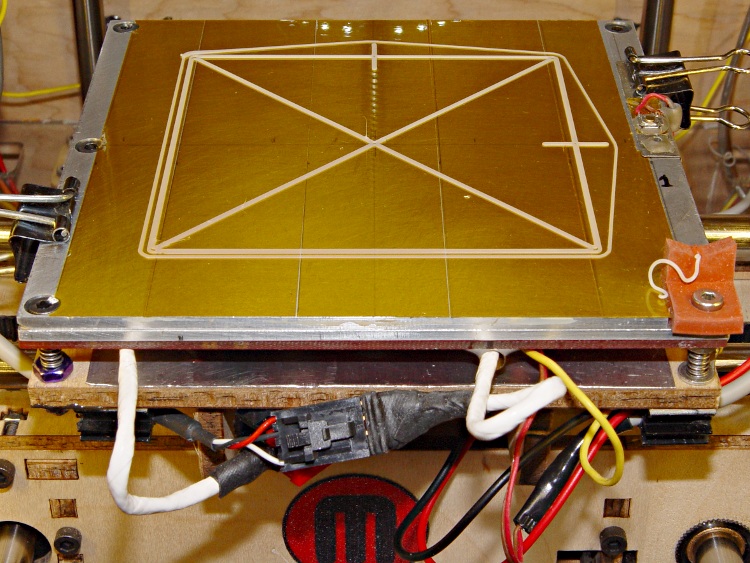
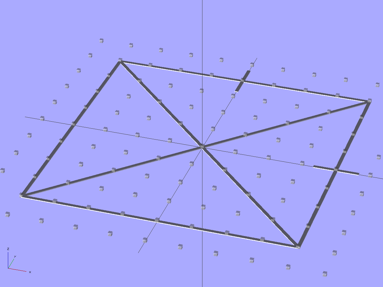
    After building a few large objects (about which more later) and verifying that the Z-minimum switch remains stable and delivers useful results, I cobbled up a test script that simplifies measuring the build platform tilt and extrusion thickness for a given switch height value.

    The pattern looks about like this, although the G-Code script below connects the top of the X so it hangs together better.

    Test X extrusion pattern
    Test X extrusion pattern

    The extrusion uses my defaults for the first layer: 0.33 mm layer thickness, 2.0 w/t, 10 mm/s, 0.66 rev/min. Those are 20% of the normal extrusion speeds: 50 mm/s and 3.3 rev/min.

    I built all the objects without adjusting the plate tilt to determine if all three plates produced the same result: they do! The results showed a consistent tilt, with the rear left corner high by 0.10 mm and the front right corner low by 0.10 mm. Those are all rubbery numbers, with accuracy based on measuring a filament, but they’re reasonably consistent.

    The Z-min switch set the middle of the platform to about 0.35 mm, making the corners around 0.25 mm and 0.45 mm. That led to slightly too much plastic (plate too high) and slightly too little (plate too low), respectively, but the objects printed quite well.

    Running the G-Code below under those conditions produced these numbers:

    30 29
    32 30 34 33
    30 32 41
    28 36

    The numbers come from two measurements on each side of the outer square at about the 1/4 and 3/4 points, plus four measurements near the middle of the X. I didn’t average multiple measurements, some are definitely off due to error, and your mileage will vary.

    Those thicknesses aren’t quite the same as I’d been seeing around printed objects, but if you squint you can see the tilt. There’s one missing number; that part of the X broke off and vanished somewhere between the Basement Laboratory and my upstairs desk.

    I tightened the rear left bolt 1/6 turn (about 0.08 mm) to lower that corner and raise the opposite one, then stuck a sheet of 8-mil (0.008 inch = 0.021 mm) shimstock under the upper plate to see how the switch handled an abrupt change in plate height:

    Built plate on 8 mil shimstock sheet
    Built plate on 8 mil shimstock sheet

    Another text X extrusion produced these thicknesses:

    25 26
    28 27 34 30
    29 31 30 38
    28 36

    It’s obviously tilted even worse than before, which means the shimstock has the odd nick, bend, or bit of grit. What’s important, however, is that the extrusion thickness remains pretty close to normal, despite having the build surface 0.22 mm higher than usual. Without the Z-min switch on the plate, the extrusion thickness would suddenly decrease by 0.21 mm… and that’s enough to wreck a print!

    Removing the shimstock and running another test extrusion produced about what I expected:

    35 32
    36 24 35 33
    30 36 35 38
    29  35

    Overall, the thickness now lies within 0.05 mm of the 0.33 mm average. My measurement accuracy simply isn’t good enough to get any better than that.

    The evidence so far suggests the platform tilt remains reasonably constant, even as the overall height varies, so I think a Z-minimum switch on the build platform should compensate for the changes that affect first layer extrusion thickness.

    What that means: slice an STL into G-Code and fire the Thing-O-Matic!

    This Level Test.gcode file, which is basically my start.gcode and end.gcode laminated around the snippet that draws the boxed-X pattern, lives in ~/ReplicatorG/scripts/calibration and thus appears on RepG’s pulldown menu:

    (---- start.gcode begins ----)
    (MakerBot Thing-O-Matic with aluminum HBP and Z-min platform switch)
    (Tweaked for TOM 286 - Ruttmeister MK5 stepper extruder mod)
    (Ed Nisley - KE4ZNU - May 2011)
    (- set initial conditions -)
    G21		(set units to mm)
    G90		(set positioning to absolute)
    (- begin heating -)
    M104 S210 T0	(extruder head)
    M109 S120 T0	(HBP)
    (- coarse home axes -)
    G162 Z F1000	(home Z to get nozzle out of danger zone)
    G161 Y F4000	(retract Y to get X out of front opening)
    G161 X F4000	(now safe to home X)
    G92 X-53.0 Y-59.0 Z117.0	(set XYZ coordinate zeros)
    (- fine home axes)
    G0 X-51 Y-57 Z115 F400	(back off switches)
    G161 Y F200
    G161 X F200
    G162 Z F200
    G92 X-53.0 Y-59.0 Z117.0	(re-set XYZ coordinate zeros)
    (- manual nozzle wipe)
    G0 X0 Y0 Z10	    (pause at center to build confidence)
    G4 P500
    G0 X40 Y-57.0 Z10	(move to front, avoid wiper blade)
    G0 X56            (to wipe station)
    G0 Z6.0           (down to wipe level)
    M6 T0			        (wait for temperature settling)
    G1 Y-40	F1000		  (slowly wipe nozzle)
    (- home Z downward to platform switch)
    G0 X55.9 Y8 Z3	      (get over build platform switch)
    G161 Z0 F50	          (home downward very slowly)
    (-----------------------------------------------)
    (- Set the Z height based on the switch height  )
    G92 X55.7 Y8 Z1.45
    (-----------------------------------------------)
    G0 Z6.0			          (back off switch to wipe level)
    (- start extruder and re-wipe)
    G0 X56 Y-40     (set up for wipe from rear)
    G1 Y-57.0 F1000 (wipe to front)
    M108 R2.0	      (set stepper extruder speed)
    M101		        (Extruder on, forward)
    G4 P4000  	    (take up slack, get pressure)
    M103		        (Extruder off)
    G4 P4000  	    (Wait for filament to stop oozing)
    G1 Y-40	F1000		(slowly wipe nozzle again)
    G0 X0           (get away from wiper blade)
    (- manual splodge)
    G0 X0 Y-58		  (to front center)
    G0 Z0.5 		    (just over surface)
    M108 R2.0	      (set stepper extruder speed)
    M101            (start extruder)
    G4 P2000        (build up a turd)
    (---- start.gcode ends ----)
    (--------------------------)
    (- print thread around platform)
    ( Speed as in Raft plugin for first layer)
    ( Print continuously to make it hang together while measuring)
    M108 R0.66				(set stepper extruder speed)
    G1 X-45 Y-45 Z0.33 F600	(to front left corner)
    G1 Y45
    G1 X45
    G1 Y-45
    G1 X-45					(return to front left)
    G1 X40 Y40				(diagonal to rear right)
    G1 X-40					(to rear left)
    G1 X45 Y-45				(diagonal to front right)
    (--------------------------)
    (---- end.gcode starts ----)
    (Tweaked for TOM 286)
    (Ed Nisley - KE4ZNU - May 2011)
    (- inhale filament blob)
    M102		(Extruder on, reverse)
    (- turn off heaters)
    M104 S0 T0 	(extruder head)
    M109 S0 T0 	(ABP)
    (- move to eject position)
    G162 Z F1500	(home Z to get nozzle away from object)
    M103		(Extruder off)
    G0 X0		(center X axis)
    G0 Y40	(move Y stage forward)
    (---- end.gcode ends ----)
    

    Things are looking good!