Ed Nisley's Blog: Shop notes, electronics, firmware, machinery, 3D printing, laser cuttery, and curiosities. Contents: 100% human thinking, 0% AI slop.
Tag: Improvements
Making the world a better place, one piece at a time
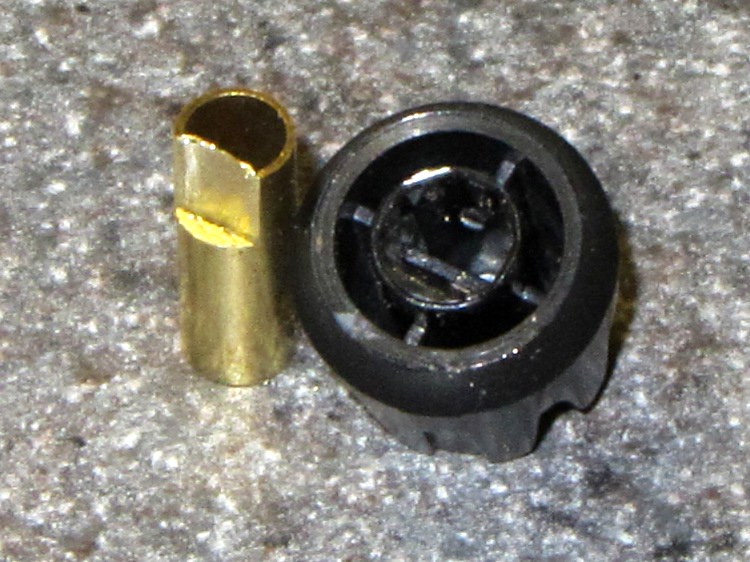
Clamp a cutoff chunk of 3/16 =0.1875 inch diameter brass tubing in the lathe and file down one side to put the flat 0.150 inch from the far side, so that the knob is a tight slip fit. If you happen to have some solid rod, that would work just as well. In this case, the file pushed the paper-thin brass remnant into the tubing and I didn’t bother to clean it out:
KG-UV3D knob with fixture
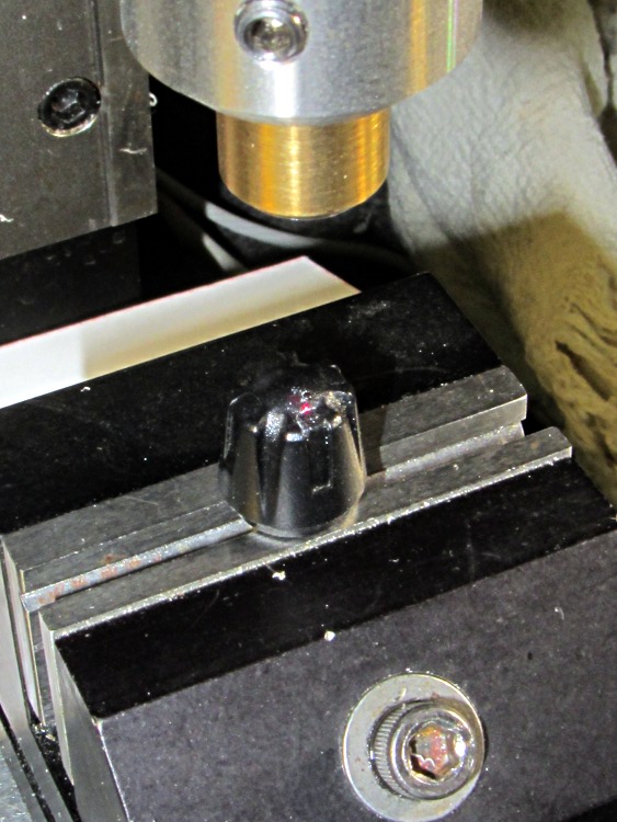
Clean the white glop off the knob, jam the knob on the fixture, clamp the fixture in the Sherline’s vise, use laser targeting to center the spindle on the notch adjacent to the minuscule pip on the knob:
Laser aligning to knob feature
Drill a 2 mm recess that en passant obliterates the pip:
Drilling index recess
Fill it with some light gray paint that just happens to be on the shelf:
Knob with filled index mark
And, by gosh, it really does dress up the radio! [grin]
Wouxun KG-UV3D with improved knob
While I had the Sherline set up, I did the knob for the other radio, too.
My buddy Duggles, from far-off NH, restored his ’83 Vanagon to its original hippie-chick-magnet state. Late in the process, he realized that the once-fancy CD+radio widget in the dashboard lacked a line input for his iPod / iPad / iDingus. Knowing my foibles, he asked for advice.
Fortunately, he’d already discovered the service manual, without which life is always much more difficult. Search for PIONEER DEH2850MP SERVICE MANUAL and pick the site you prefer.
The trouble with jamming a new line input into the existing circuitry is that you must match the DC levels as well as the audio amplitude. The schematic on page 19 shows the selector IC has capacitor-coupled inputs and outputs to strip off the DC level.
It would be very easy if the multiplexer (IC151, top of page 19, detail shown) had separate control inputs that we could override, but it uses a serial control stream from the CPU. No practical way to mess with that, alas.
As nearly as I can tell, the best way to do this would be to hack a DPDT switch between the FM/AM tuner and the amp, upstream of the mux. You pick the Radio input, flip the DPDT switch, and the iDingus plays through the Radio inputs.
However, an easier way is to simply inject the iDingus audio in parallel with the tuner audio, but set the tuner to an FM frequency without a radio station. The radio output should mute, leaving the field clear for the iDingus audio. This might not work, but it’ll be dead simple to try. If it’s acceptable, then you’re done.
The obvious problem is that we don’t know if the iDingus line level matches the tuner’s line level. The mux is upstream of the volume settings, so there’s hope that this will all Just Work. If it’s way too loud, that’s fixable. If it’s too soft, that’s a problem.
So, to begin…
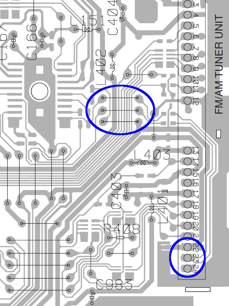
DEH2850MP PCB Radio Jumpers
The diagram on page 36/37 shows the A side of the PCB, with all the connectors & suchlike. The FM/AM Tuner Unit is over along the right side, with the audio output on pins 23/24 near the bottom and ground on pin 22. The traces proceed upward along the edge of the PCB, cross the connector near its middle, the audio passes through caps C151/152 on the B side, go through two jumpers on the A side across a mess of traces, and then dive to the B side and wriggle into the IC151 mux.
Quite conveniently, the ground trace follows along with them and is the lower of the three traces just to the right of the mux.
If I interpret the part number for C151 correctly (page 45, top right):
C 151 ... CKSRYB224K10
it’s a 220 nF cap. Anything around that value should work. This one from Radio Shack is grossly overpriced; anything with the same or larger value is OK (voltage rating doesn’t matter): NTE MLR224K100 – 0.22MF 100V Mylar Capacitor
Solder one lead of each cap to the top two jumpers, solder suitable wires to the other cap leads, solder the ground / shield wire to the bottom jumper, solder a suitable jack to the cable, plug iDingus into jack, fire that mother up, and see what happens.
The right channel is on pin 24, which goes to the top jumper of the three. Don’t bother trying to figure out which pin of the iDingus corresponds to that channel; just solder the damn wires and fix it later if it’s wrong enough to be objectionable.
I have no idea where or if you can drill hole(s) to snake the cable(s) through the housing. If the Vanagon doesn’t have a rear power amp, you could probably cut the traces under those RCA jacks (CN352, top right on page 37, above the FM/AM tuner) and repurpose them.
Give it a go…
We both attended Lehigh U, but Duggles realized early on that he lacked the personality flaws common to engineers and bailed out before damaging himself too badly. So his reply didn’t surprise me in the least…
I read your instructions carefully, examined the kindly supplied circuit diagram, and pored over the circuit boards with a magnifier. Then I blew you off (!!), threw caution to the winds, hacked off an old headphone cord, snaked the wires in, and soldered right to the very convenient L/R outputs on the RF board. Fired it up ,,, shitz, tons of background hiss, no quieting on the FM signal! A skein of obscenities was loosed in the mountain air until I thought to turn the iThang on … boom, full quieting, no hiss, and a quite substantial sound. No level issues at all, quite clean and detailed, and I didn’t even use the capacitors! (What was their purpose btw?)
The mux has a DC bias on its signal lines, with caps on both the input and output to isolate it from the surrounding circuitry. Back in the day, analog switches were fussy about their DC bias, so you had to go overboard to make them work at all.
I don’t know if the iDingus also has DC blocking caps on its output and figured that injecting raw DC from the mux into its guts could be a Bad Thing. But, eh, those engineers at Apple (‘s contractor) are smart folks and (probably) anticipated this sort of (mis)behavior.
The hiss you get with the iDingus turned off probably comes from dragging the mux bias to ground. I don’t know that’s a Truly Bad Thing, but adding those caps should eliminate any future problems.
You could even play DJ by combining radio & iDingus audio!
Rock on…
Seeing as how Duggles actually was a DJ for quite some years, I wouldn’t be surprised in the least to hear he does exactly that. We’ll be visiting him later this Autumn and I’ll inspect his work.
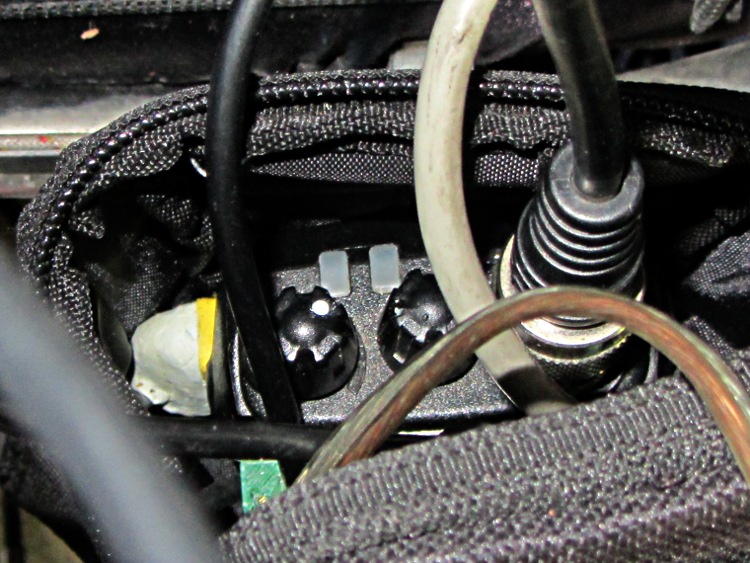
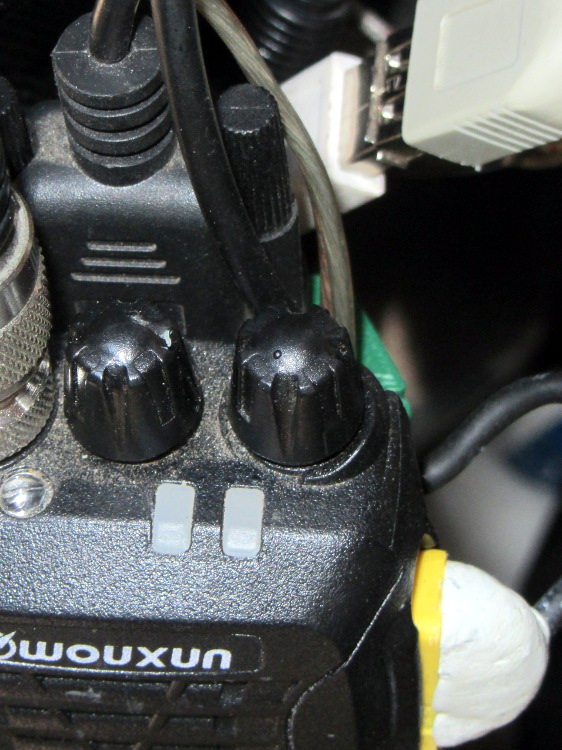
The volume / on-off control knob on our Wouxun KG-UV3D radios has the most minute raised dot you can imagine to mark its orientation. Yes, it’s another subtle black-on-black control! See if you can spot the dot:
Wouxun KG-UV3D – volume knob marking
The radio lives in a small pack attached to the back of the seat frame: we turn it with a fingertip and adjust the volume by touch; the dot is just barely perceptible to my finger. Nevertheless, WIBNI (Would It Be Nice If) you could look at the knob from a distance and determine whether the radio was turned on?
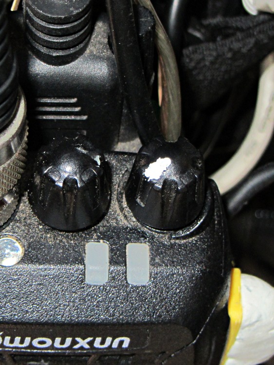
A dab of typewriter (remember typewriters?) correction fluid later:
Wouxun KG-UV3D – garish knob marking
Not elegant and sure to wear off after a while, but the smudge should remain visible forever.
Our Larval Engineer acquired a free bicycle to get around at school: a Rollfast “girl’s bike” dating back to 1972 with 105 miles on the odometer. She completely dismantled it, cleaned everything, reassembled it in reverse order, and added a rear rack & panniers. Having touched every part of the bike, she’s now in a much better position to fix whatever may go wrong in the future.
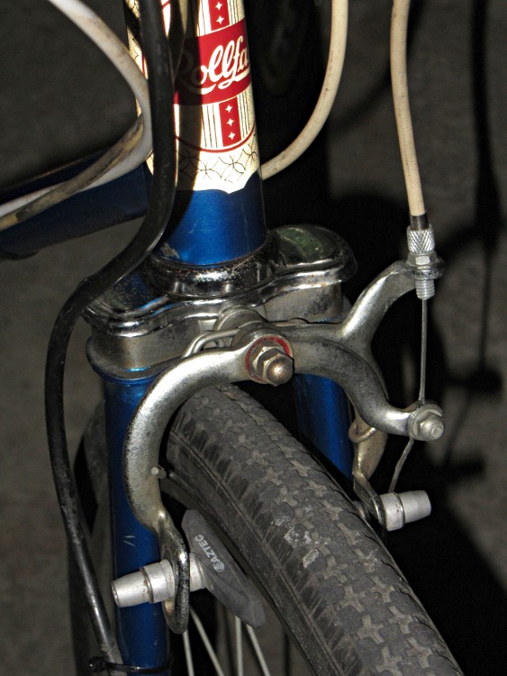
It was an inexpensive bike to start with and we left everything as-is, with the exception of the brake pads. You’re supposed to bend the brake arms to align the pads with the rims, a technique which I didn’t like even back in the day. So we swapped the OEM pads with worn-but-serviceable Aztek pads sporting spherical washers:
They’re way grippier than the old pads, even on those chromed-steel rims. I had a bike with steel rims and old pads; given the slightest hint of water, it didn’t stop for squat. With any luck, the Azteks will at least slow this one down.
Although she wanted to take the Tour Easy, the bike must live outside under the apartment stairs all year and, frankly, that’d kill the recumbent in short order. Forgive me for being a domineering parent; when she has a good place to store a spendy bike, it’s hers for the taking.
We haven’t figured out how to mount the GPS/APRS tracker + radio and antenna. The evidence suggests she prefers to travel incognito from now on…
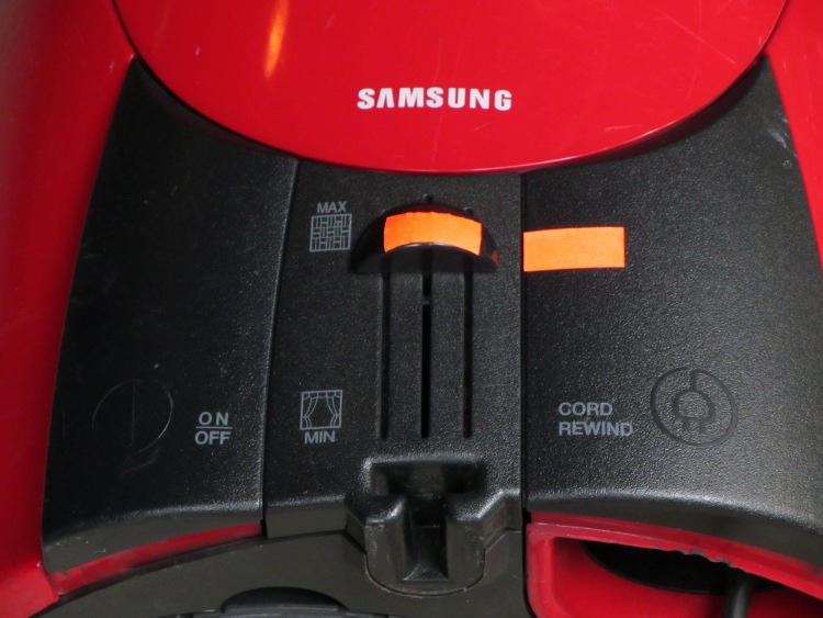
After having discovered, once again, that the vacuum cleaner wasn’t cleaning very well because the suction control was knocked halfway down the scale, I made the normal setting on the damn thing visible:
Samsung vacuum cleaner control labeling
I don’t know why a label in dark-gray-on-black is such a wonderful idea, given that SAMSUNG stands out in pure white-on-red. Designers love subtle touches; I suppose they expect you to just puzzle it out and memorize the right answer.
The embossed / raised black-on-black symbols don’t work for me, either. Did you spot the one to the left of the ON/OFF label? Didn’t think so.
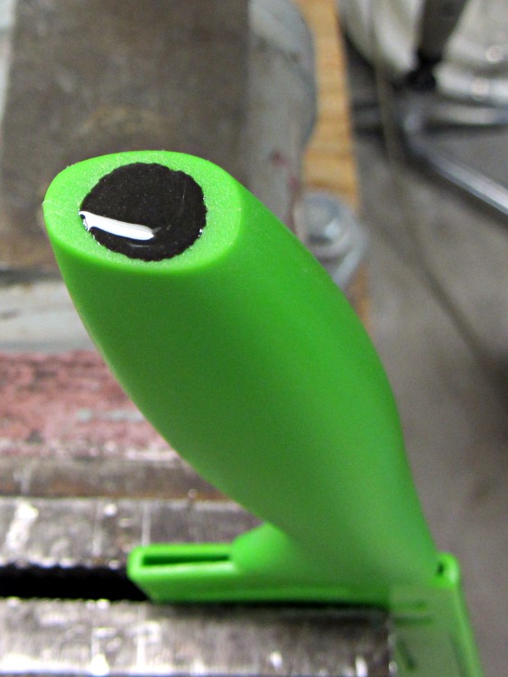
So I bought a lurid green $8 Tomodachi Santoku knife at K-Mart, which was the first non-stick-coated Santoku-shaped knife I’d seen since that comment. It’s made by Hamilton Forge Ltd, one of those generic names that doesn’t produce any search results worth mentioning and so probably isn’t a real company:
Tomodachi Santoku knife
The knife has a huge steel blade with a solid plastic handle injection-molded around a short tang, which put the balance point maybe 50 mm out into the blade. I didn’t like the feel when I waved it around in the store and really didn’t like how it behaved on the cutting board.
The way I see it, I can fix a too-light handle…
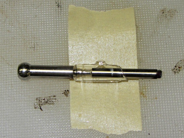
Pursuant to that post, I have a bag of tungsten electrodes, some complete with a glass seal:
Tungsten electrode with glass seal
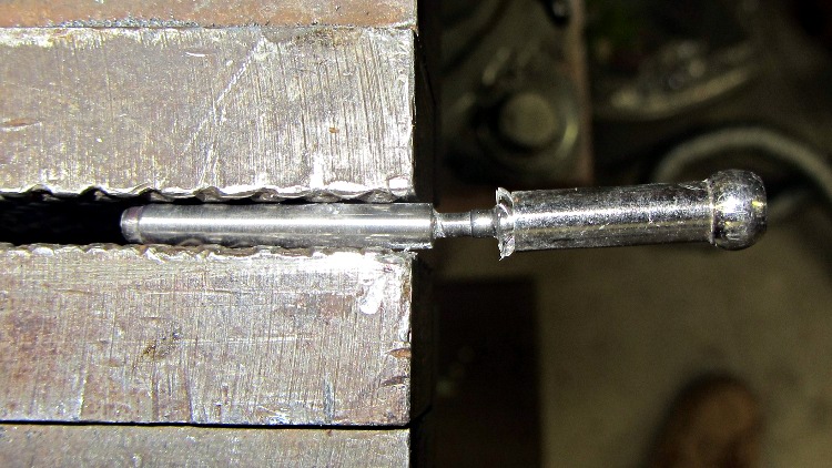
Wrapping some masking tape around the glass, tapping it with a hammer, then sliding the tape-with-fragments into the trash got rid of the glass. The bulbous tip seems to be a stainless steel tube welded around a thin tungsten shaft, so I clamped it in the vise and whacked it with a chisel; tungsten is strong-but-brittle and cracks easily:
Fracturing tungsten electrode
Of course, whacking a tungsten rod didn’t do the chisel the least bit of good, but it was about time to sharpen that thing anyway.
Why use tungsten electrodes instead of, say, ordinary drill rod? Tungsten has about the highest density you can get without going broke, getting poisoned, or dying of radiation exposure. That useful table gives elemental density in g/cm3:
aluminum = 2.7
iron = 7.9
lead = 11.4
gold = 19.32
tungsten = 19.35
osmium = 22.6
Can’t afford gold, not even I would put a lead slug in a kitchen knife, and I had the electrodes, so why not?
Waving a neodymium magnet over the handle convinced me that I could drill a hole slightly more than two inches deep without hitting the tang. I briefly considered drilling half a dozen smaller holes, but that started to look like a lot of work and I don’t have any suitable gun drills.
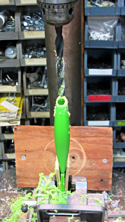
The business end of the electrode measures 1 inch long and 0.1375 inch in diameter. A hexagonal cluster of seven rods fits neatly into a round hole about 3×0.137 = 0.413 inch in diameter: quite conveniently a nice, long Z drill. So I clamped the knife between two strips in the drill press vise and had my way with it:
Drilling knife handle
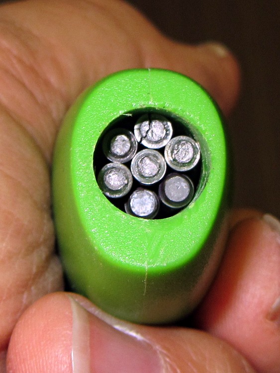
Actually, I spot-drilled with a center drill, then used a long step drill, stopping with the 3/8 inch step just kissing the low side of the handle, to get the hole mostly on center, before running the Z drill down about 2-1/8 inch. The handle walls became so thin that they flexed around the drill to produce an undersized hole, so I reamed it with a hand-turned 7/16 inch drill and the electrodes fit with no room to spare:
Tungsten electrodes in knife handle
Yeah, that’s a crack in the top electrode: tungsten is brittle.
A dollop of epoxy atop the electrodes should seal them in place forever. I clamped the knife (in its color-matched scabbard) with the angled end of the handle water-level, so the epoxy settled in a neat, symmetric blob that looks better in person than it does here:
Epoxy seal over tungsten weights
The epoxy forms a plug over the ends of the electrodes and (probably) doesn’t extend very far down between them, but they’re firmly jammed in a snug hole and (probably) won’t ever rattle around.
Seven electrodes weighed 32 g and, figuring the missing plastic rounds off to slightly over nothing, the handle now has 60 g of additional weight out toward the end, producing a knife weighing 185 g that balances near the narrowest part of the handle. It’s somewhat heavier than I’d like, but I can cope.
The edge came from the factory reasonably sharp; a few passes over the sharpening steel touched it up nicely.
Early results: it cuts cheese perfectly, drifts to the right in melons, cuts wafer-thin slices from a loaf of my High-Traction Bread, and dismantles fruit with some clumsiness. Overall, I like it, although I could do without the bright green color in a big way.
The Wouxun KG-UV3D is advertised as a “dual band” radio, but it has only one hardware receiver: in TDR mode (there is no explanation of what TDR means, so there may not be an English equivalent; I suspect it’s not Time Domain Reflectometry) with two frequencies / channels displayed, the first to receive a transmission produces audio output until that signal stops, regardless of what happens on the other frequency / channel. In contrast, the ICOM Z1A and W32A radios we were using had two hardware receivers and the audio output was the sum of the two signals, with independent volume controls.
That wouldn’t matter, except that I monitor the E911 dispatch channel while riding, so that I know when an emergency vehicle will be coming along my route: distracted drivers are bad enough, but a distracted driver dodging an ambulance is really bad. The E911 transmitters have punchy audio compared to anything else, so it’d be nice to turn down the dispatcher’s level compared to the relatively quiet voice + APRS signals on the other channel.
No can do.
The KG-UV3D also requires much higher audio on the mic input than the Z1A for the equivalent output. Contrary to that schematic, I’m now running the op amp gain at about 4.5 (13 dB) instead of 1.6 (4 dB): it’s a 100 kΩ feedback resistor. That puts it on a par with the E911 audio, but it’s still somewhat quiet.
The TinyTrak3+ board produces audio tones through a 4-bit binary resistor network that feeds into a 220 kΩ resistor in series with the 10 kΩ trimpot that sets its output level. Cranking that pot all the way up produces roughly the same volume as the +13 dB helmet mic audio. If I increase the mic gain any further, however, I should also increase the TT3+ audio output, which means reducing the 220 kΩ resistor on the TT3+ board. The TT3+ doc advises:
Some mobile radios require more audio drive than TinyTrak3 puts out. If audio levels are too low, even with the R6 pot set to maximum, consider replacing the 220K R5 with a 100K resistor or shorting jumper. This should allow for about double the audio range.
Dunno if that means another 3 or 6 dB or what, but it might come in handy.
However, increasing the mic gain has the disadvantage of causing more wind noise: it’s always there and high mic gain makes it much worse. The foam balls over the mics work well, but the voice volume drops off dramatically as the mouth-to-mic distance increase; about half an inch is a good distance. So there’s an upper limit on mic gain.
I’ve also increased the earphone attenuation, with a 150 Ω resistor in series with the earbud, to give the receiver volume control more useful range.
It’s workable as it stands and the many APRS receivers have no trouble decoding the packets, so all this is in the nature of fine tuning. I do miss the dual audio outputs, though…