Ed Nisley's Blog: Shop notes, electronics, firmware, machinery, 3D printing, laser cuttery, and curiosities. Contents: 100% human thinking, 0% AI slop.
Tag: Improvements
Making the world a better place, one piece at a time
After a few sessions of soldering-and-checking, it looks good:
HT-GPS PCB – cabled in place
The yellow wires on the far right are temporary power connections; battery power enters through the contact studs in those large holes that press against the radio’s battery terminals. The cable in the lower right is the mis-color-coded USB cable that carries audio to & from the earbud & mic on the helmet. Not all the pads have components; I didn’t use all the parallel bypass cap locations because I wasn’t up for protracted self-resonance measurements.
The TinyTrak3+ cable solders into the empty DB9 footprint over on the left. I must cannibalize that from the ICOM IC-Z1A interface in Mary’s bike after the next Wouxun KG-UV3D arrives; with any luck, there’ll be a rainy day or two for that work.
The as-built schematic (clicky for more dots), which is pretty close to the original intent:
Schematic – Wouxun HT GPS+Voice Interface – August 2012
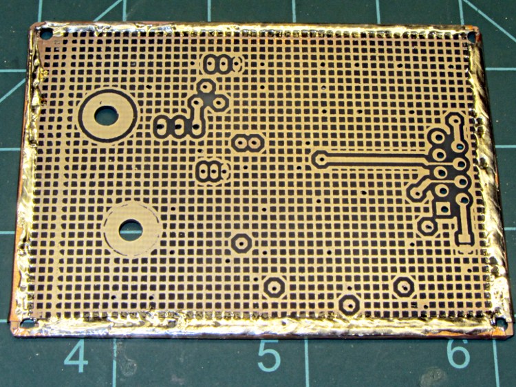
Drilling the PCB went fine, as did the etching & silver plating:
PCB with edge wrap – front
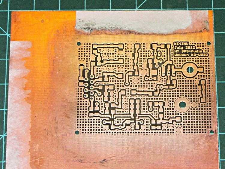
The rear side has a fine ground plane:
PCB with edge wrap – rear
The small spots scattered over the rear mark vias that stitch the front and back planes together; lacking plated-through holes, I solder nippets of 24 AWG wires to both sides. The wrinkly edge comes from solder on the copper foil binding the entire perimeter.
While I have no hard evidence that all of the fuss & bother matters, the most recent version of this circuit is the quietest yet: the machine noise from the TinyTrak3+ that plagued the first iteration has pretty much vanished.
I’ll grant you that the silver plating doesn’t look very silvery in these pix, but it’s quite different from the bare copper in person. Here’s the front just after rubbing it in with a vigorous circular motion:
After replacing the Y axis leadscrew, I decided that the X axis leadscrew was in fine shape, because it’s tucked under the table and not exposed to the swarf and grit that fell on the Y axis screw before I installed the bellows. Being that sort of bear, I couldn’t throw out the worn Y axis leadscrew, so I had two rather delicate rods that really needed more protection than a twist of paper.
So I sawed off a length of 1 inch PVC pipe, faced the ends in the lathe, and added two rubbery endcaps from the heap:
Sherline leadscrews stored in PVC pipe
That fits neatly into the big box alongside the rotary table, with the bag of assorted nuts so they’re all together.
Despite what you see there, the screws are wrapped in paper with a bit of oil, so it’s all good.
A three-pack of 100-tooth 2 inch cutoff saw blades followed me home from Harbor Freight a while ago. Although they’re intended for a craptastic HF tabletop saw, I thought they might come in handy on the Sherline for slicing lengths of brass tubing. The reviews for the saw indicate the blades are no good for steel, barely adequate for brass, and dandy for wood; they have nowhere near enough teeth for a screw cutoff blade.
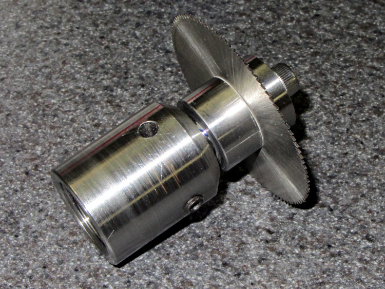
None of the arbors in my collection fit a blade with a 3/8 inch hole, so a bit of lathe work produced one while the 3D printer cranked out a GPS+audio case:
Cutoff saw arbor in Sherline toolholder
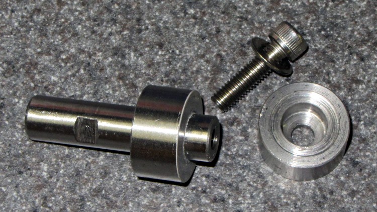
The shaft is 3/8 inch drill rod and the collars are 3/4 inch drill rod, both of O1 oil-hardening steel that will remain forever unhardened, fitting into a Sherline endmill toolholder. I drilled-and-bored the collars to a slip fit on the shaft, then epoxied the rear one in place:
img_2156 – Cutoff saw arbor – parts
I drilled a 0.6 inch deep blind hole in the shaft and tapped it 10-32 all the way down for a 1/2 inch SHCS. A bag of assorted 10-32 taps produced a bottoming tap that came in handy, but I put tapping in the same category as parallel parking: I’ll walk half a mile to not parallel park the van. Couldn’t avoid it this time.
The flat on the shaft came from a bit of hand filing, which was easier than setting up the mill.
The front collar’s undercut ensures just the rim contacts the blade. The photo shows the vanishingly thin layer of epoxy on the rear collar that mooshed out as I clamped the stack together:
Fixed (rear) collar
Waxed paper with a 3/8 inch hole punched in the middle
Cutoff blade
Split lockwasher for a bit of space
Loose (front) collar
Socket head cap screw
After the epoxy cured, a pass through the lathe skimmed off that thin epoxy layer and trued up the fixed collar face to eliminate the last bit of wobble. The radial runout remains just enough so that one tooth tings before the others engage, but I’m not entirely convinced that’s due to the (minimal) shaft-to-blade clearance.
In use, putting the split lockwasher between the loose collar and the SHCS provides a little clamping compliance.
At some point, I’m sure this thing will come in handy…
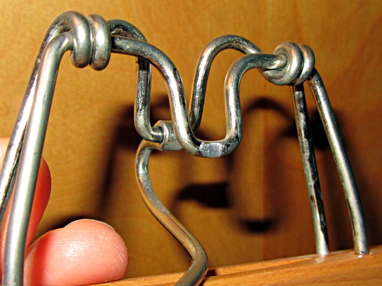
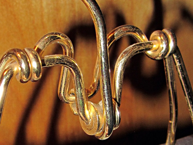
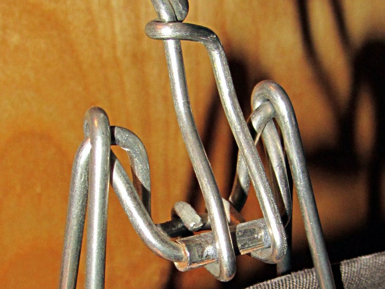
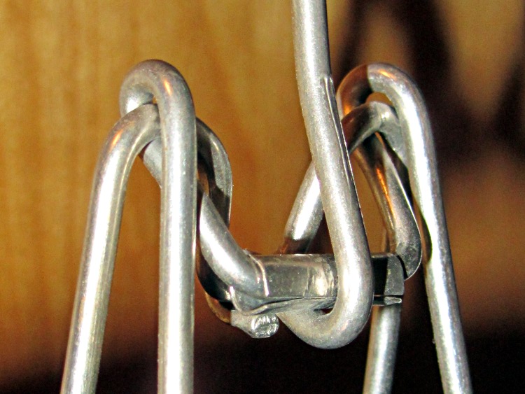
So I finally looked at why one of the trouser hangers made a nasty gritty noise. Turns out that, no suprise, when you rub steel against steel long enough, it wears away:
Trouser hanger – abraded steel
Another hanger had a huge roller that worked wonderfully well:
Trouser hanger – elaborate roller
That one was obviously over-engineered, but a simple roller also works well:
Trouser hanger – simple roller
They cheapnified this one just a bit too much, because it’s not quite a roller any more:
Trouser hanger – ineffective roller
A bit of rummaging turned up enough hangers with working rollers, so it’s all good now…
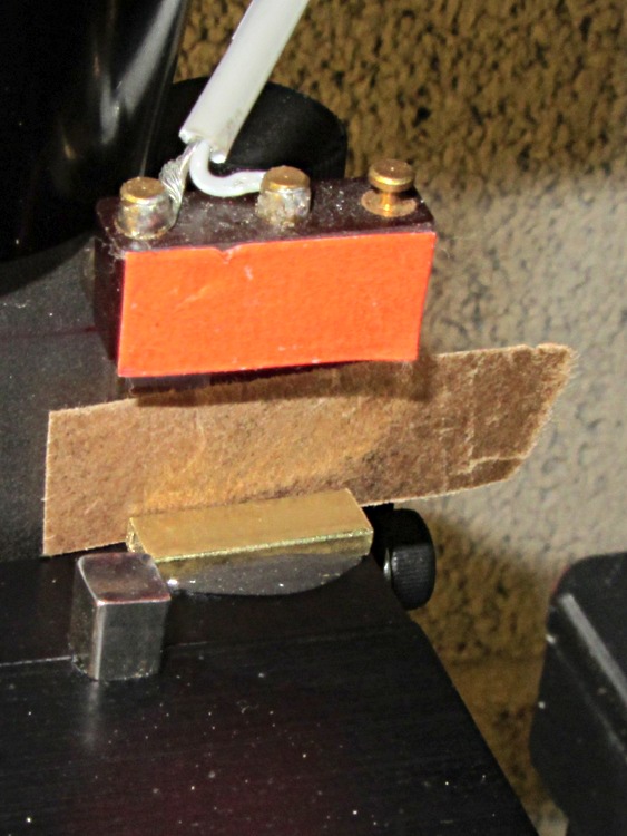
After drilling that PCB, I noticed that the Z axis saddle locking lever (which also functions as the backlash adjustment) had come loose. It turns out that if you don’t tighten the thumbscrew or it works loose, then the locking lever can turn with the leadscrew and, at the very top of the Z axis travel, can walk off the leadscrew thread.
A snippet of rectangular brass tubing epoxied to the top of the Z axis saddle solves that problem by removing 3/32 inch of precious travel. A slip of brown waxed paper (yes, harvested from the new Y axis leadscrew wrapper) kept the epoxy off the dovetail.
Just for consistency, I removed 0.09 inch from the Z axis home offset, but that really won’t make any difference.
HOME_OFFSET = 6.84
HOME = 6.5
Now, I’d put the switch in that position because the saddle jams against the preload nut exactly at the end of the switch button travel. Now I can crush the switch by manually running the Z axis beyond its Home position …
While I had the tooling plate off, I cleaned the crud out of the tapped holes and ran a handful of 1/4 inch stainless steel 10-32 setscrews just below the surface:
Sherline tooling plate with setscrews
They’re pretty much invisible, of course, but they’re all present. FWIW, you need a 3/32 inch hex wrench for 10-32 setscrews.
In the event that I gouge the aluminum surface (you can see the odd ding and blind hole) through a setscrew, I’ll regret doing this. Not having to remove the plate to dig swarf out of the last clamping hole after carefully aligning a part seems like a win.