Ed Nisley's Blog: Shop notes, electronics, firmware, machinery, 3D printing, laser cuttery, and curiosities. Contents: 100% human thinking, 0% AI slop.
Tag: Improvements
Making the world a better place, one piece at a time
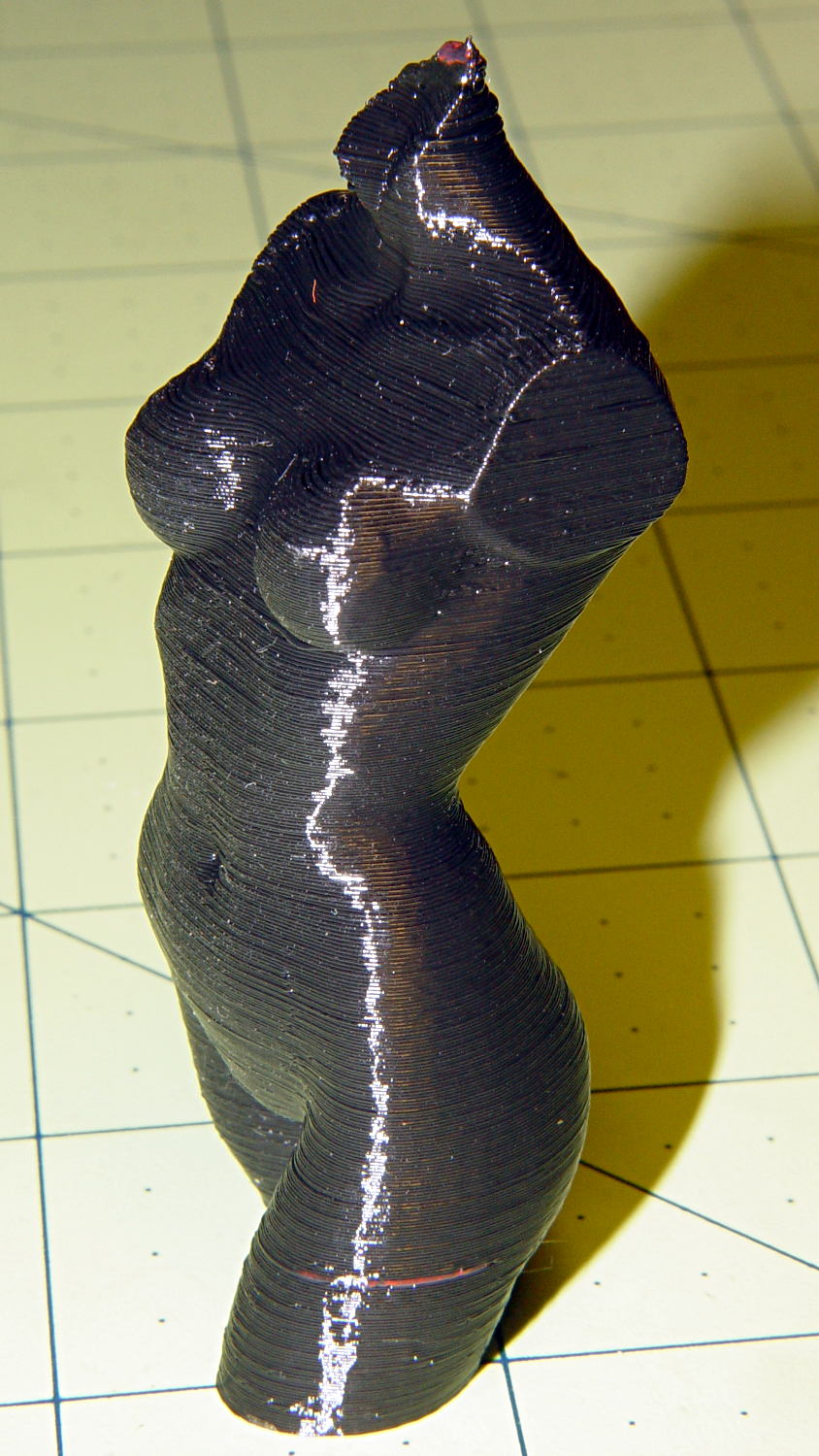
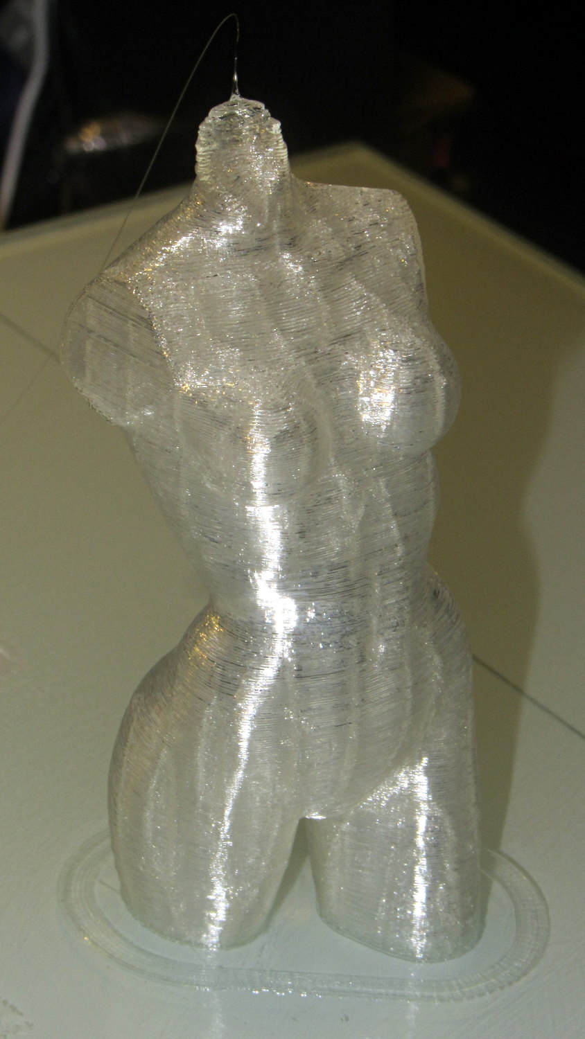
Done in natural PLA, as it seems the previous version also walked off:
Pink Panther Woman – natural PLA
The attentive reader will note an odd red stripe on the left leg of the black PLA version. Here’s a closer look:
Pink Panther Woman – black with red contamination – detailPink Panther Woman – black with red contamination – detail
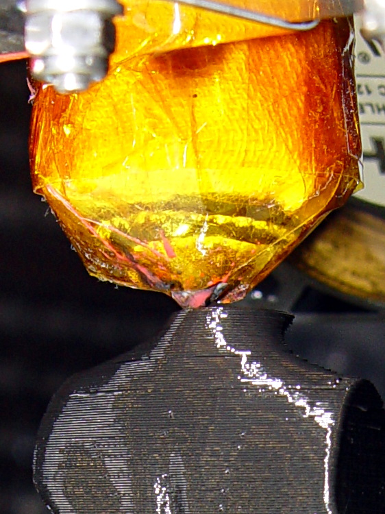
I had recently changed from red to black PLA and, as usual, purged the extruder with a few hundred millimeters of black filament, until it emerged pure black. Alas, I forgot to wipe the outside of the nozzle:
Pink Panther Woman – black – contaminated nozzle
That red blob produced the red tab on the neck, as you can see if you look carefully at the first picture.
There are very few visible imperfections in either object: the state of DIY 3D printing is pretty good.
(*) Does anyone know of similar male figures suitable for this purpose? That torso seems to be about the extent of Thingiverse’s offerings.
The improved platform was designed for a 30 V supply that would run it at about 150 W, which took slightly less than forever to reach operating temperature.
With the 36 V supply set to 38.6 V, the platform drew 6.2 A at room temperature, which worked out to 6.2 Ω and 240 W. It was a tad pokey getting up to temperature
At 40 V, the platform starts at 6.3 A / 6.3 Ω / 250 W from a bit over room temperature and drops to 5.8 A / 6.9 Ω / 232 W at 70 °C.
At about 250 W, the platform takes about three times longer to reach operating temperature than the extruder, but it doesn’t require calling down to the engine room for more coal before maneuvering. I must run some numbers on it, now that I have a power supply with a useful range.
There’s obviously an upper limit to the peak power the PCB traces under the glass can handle, but it runs at the same average power (to produce the same average temperature) and, at least so far, hasn’t shown any signs of distress. The few additional watts at 40 V won’t make any difference.
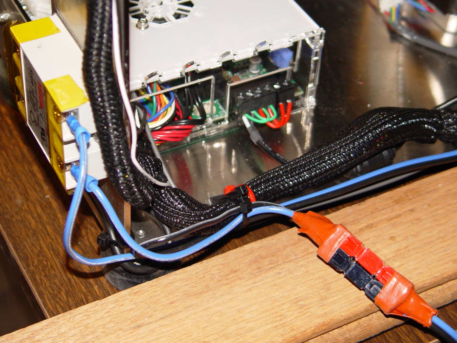
Note that you must use an external DC-to-DC solid state relay, because the Rambo controller board can’t handle anything over 24 VDC and high current loads tend to melt its Phoenix-style connectors. When you add the SSR, replace the HBP connectors with Anderson Powerpoles, use fat wires, and be done with it.
M2 HBP SSR Wiring
The M2’s Marlin firmware uses bang-bang control and tends to overshoot the setpoint; I’m not sure a few degrees makes all that much difference, particularly because it’s not measuring the temperature at the top of the glass plate.
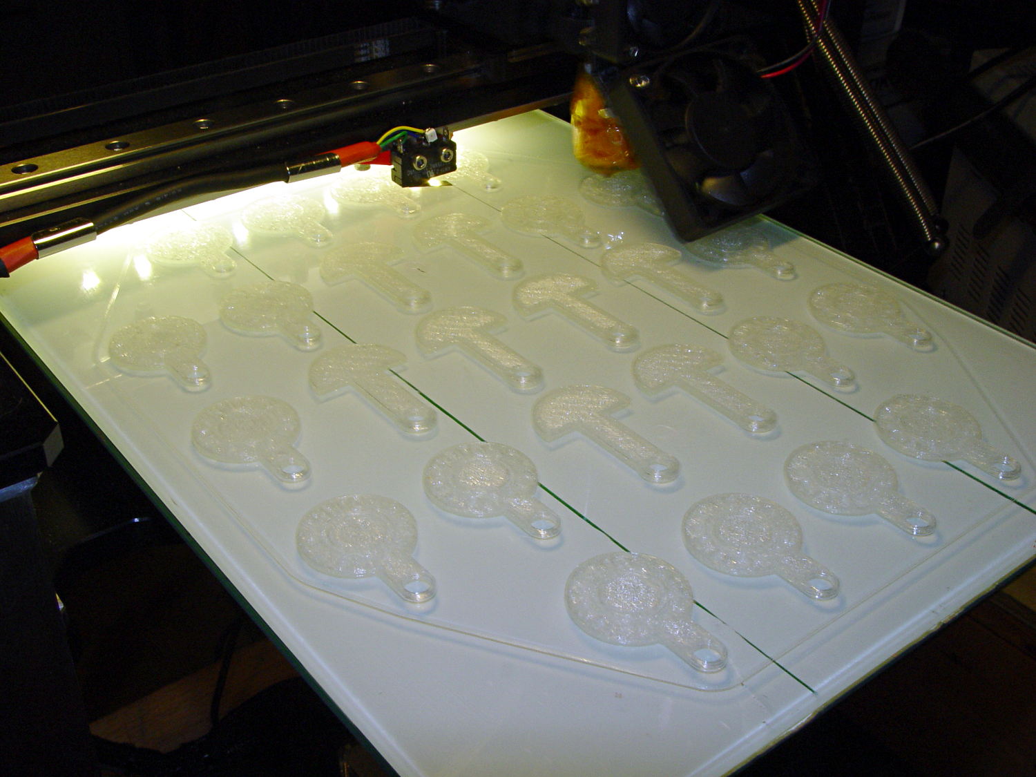
It turns out that an array of Cart Coins and Cart Releasers make a fine thickness test pattern and become useful tchotchkes when you’re done:
Cart Coins – printing
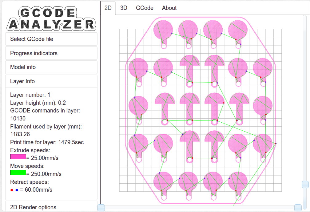
They’re a bit easier to see in the digital realm:
Cart Coins – platform layout – layer 1
The trick is that they’re both eight layers thick at 0.20 mm/layer. With the platform aligned exactly right, all the objects should measure exactly 1.60 mm thick.
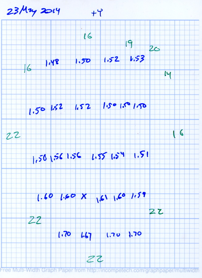
The blue numbers give the thickness measured across the stem, just above the hole, on each object:
Platform Leveling – Initial
The green numbers are the skirt thickness: 22 = 0.22 mm.
The platform has a tilt of 0.20 mm from +Y to -Y and is just about perfect from -X to +X.
The M3x0.5 adjusting screws under the (improved) platform, seen from the front (-Y) end of the platform:
M2 – Improved HBP – bottom view
The silicone plugs inside the springs are slightly compressed, so the springs are only decorative. The platform is rigidly mounted on the plugs, with only very slight compliance, and I haven’t leveled the platform in a few months.
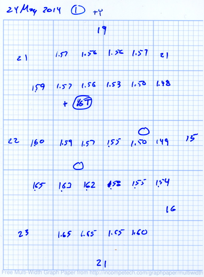
Tightening the “north” adjusting screw by 1/6 turn lowered the +Y end of the plate by about 0.05 mm and tilted the +X side slightly higher:
Platform Leveling – Adjustment 1
The skirt thicknesses are now in blue, too.
Tightening the “north” screw an additional 1/6 turn and tightening the “east” screw 1/6 turn produced an almost perfect result:
Platform Leveling – Adjustment 2
The thicknesses don’t vary quite randomly, but I think further adjustments won’t make much difference: the total range is only 0.12 mm = 1.53 to 1.65 mm. That’s pretty close to the limit of my measurement ability on the plastic pieces.
Notice that the skirt thread, which should be exactly 0.2 mm thick all around, really isn’t. I’m going to see whether a two-layer-thick skirt measures a more consistent 0.40 mm.
Depending on a solid model’s complexity, OpenSCAD will sometimes chew through system memory, consume the entire swap file, and then fall over dead. In an attempt to work around that situation, I recently jammed a 32 GB USB drive into the back of the box, turned it into a swap device, and then told the kernel to back off its enthusiasm for swapping.
Format the USB drive as a swap device:
sudo mkswap /dev/sd??   #--- unmount it before you do this!
Setting up swapspace version 1, size = 31265292 KiB
no label, UUID=0f559a8c-67b7-4fa3-a709-17aeec3104c4
Add it to /etc/fstab and set swap priorities:
# swap was on /dev/sdb3 during installation
UUID=e8532714-ad80-4aae-bee7-a9b37af63c8c none  swap sw,pri=1	0 0
UUID=0f559a8c-67b7-4fa3-a709-17aeec3104c4 none	swap sw,pri=5	0 0
Turn it on:
sudo swapon -a
Following those directions, dial back the kernel’s swappiness and limit the file cache growth:
For whatever reason, WordPress turns underscores into blanks, so those obvious typos aren’t, really.
And then it should Just Work.
The box has 4 GB of RAM and, under normal circumstances, doesn’t swap at all, so I expect the USB drive should kick in only for extreme OpenSCAD models. The swappiness tuning should help during ordinary operation with large file operations.
I have no results to report, but if something blows up, I know what changed…
Because the current control loop closes through the Arduino loop(), the code’s path length limits the bandwidth. Worse, the PWM filter imposes a delay while the DC value catches up with the new duty cycle. Here’s what that looks like:
LoopStatus ILED 50 mA div – 200 50 150 25 mA
The setpoint current for this pulse is 200 mA, ramping upward from 50 mA. It should have started from 25 mA, but the loop really wasn’t under control here.
The top trace goes low during the drain current measurement, which occurs just before the code nudges the gate drive by 1 PWM count to reduce the error between the setpoint and the measurement. A delay(1) after each PWM change, plus the inherent delay due to all the program statements, produces an update every 1.7 ms, more or less.
Even at that low rate, the current overshoots by 50 mA before the loop can tamp it down again. The current varies by 200 mA for 7 PWM counts, call it 30 mA per count at the high end, so overshooting by 50 mA comes with the territory. There’s just not a lot of resolution available.
The program reads each pulse duration and amplitude from an array-of-structs, so it’s a simple matter of software to save the gate drive voltage at the end of each pulse and restore it when that pulse comes around on the guitar again:
	if (millis() >= (EventStart + (unsigned long)Events[EventIndex].duration)) {
		Events[EventIndex].drive_a = VGateDriveA;						// save drive voltages
		Events[EventIndex].drive_b = VGateDriveB;

        if (++EventIndex > MAX_EVENT_INDEX)								// step to next event
		    EventIndex = 0;

		VGateDriveA = Events[EventIndex].drive_a;						// restore previous drives
		VGateDriveB = Events[EventIndex].drive_b;

		SetPWMVoltage(PIN_SET_VGATE_A,VGateDriveA);
		SetPWMVoltage(PIN_SET_VGATE_B,VGateDriveB);

		delay(PWM_Settle);

		digitalWrite(PIN_ENABLE_A,Events[EventIndex].en_a);				// enable gates for new state
		digitalWrite(PIN_ENABLE_B,Events[EventIndex].en_b);

        NeedHallNull = !(Events[EventIndex].en_a || Events[EventIndex].en_b);	// null sensor if all off

		EventStart = millis();                                          // record start time
	}
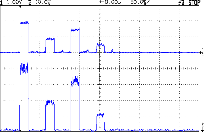
… which produces this happy result, with a different time scale to show all four pulses in the array:
I Sense Amp ILED 50 mA div – 200 100 150 50 mA
The top trace shows the current amp output that goes into the Arduino analog input and the bottom trace shows the MOSFET drain current. Notice those nice, crisp edges with a nearly complete lack of current adjustment.
The small bumps in the amp output just after the LED turns off happen while the the code nulls the Hall effect sensor offset. Whenever the LEDs turn off, the code nulls the sensor, which is probably excessive; it really doesn’t have much else to do, so why not?
This trickery doesn’t improve the loop bandwidth at all, because the code must still drag the current to meet each setpoint, but now that happens only when the pulse first appears. After a few blinks, the current stabilizes at the setpoint and the loop need handle only slight variations due to temperature or battery voltage changes.
Speaking of voltages:
VDS ILED 50 mA div – 200 100 150 50 mA
The top trace now shows the MOSFET drain voltage and the bottom still has the LED current. There’s only 650 mV of difference at the drain for currents of 50 mA and 200 mA through the LEDs, with about 1 V of headroom remaining at 200 mA.
The power supply delivers 7.4 V to the anode end of the LEDs, so they drop 6.3 V @ 200 mA and 5.7 V @ 50 mA. Some informal knob twiddling suggests that the MOSFET loses control authority at about 6.5 V, so, given that there’s not much energy in the battery below 7.0 V anyway, the program could limit the maximum current to 50 mA when the battery hits 7 V, regain 650 mV of headroom, and run at reduced brightness (and perhaps a different blink pattern) until the battery drops to 6.5 V, at which point the lights go out.
There’s more improvement to be had in the code, but those pulses look much better.
(If you’re keeping track, as I generally don’t, this is Post Number 2048: love those round numbers!)
The original 32 kHz PWM produced plenty of ripple in the LED current:
VG 1193 mV – ID 50 mA-div – 1 ms PWM filter
Using 64 kHz PWM requires putting the timers in Fast PWM Mode:
Timer 1: Mode 5 = Fast PWM, 8-bit resolution
Timer 2: Mode 3
The Arduino code that does the deed:
// Timer 1: PWM 9 PWM 10 - Hall offset
TCCR1A = B10000001; // Mode 5 = fast 8-bit PWM with TOP=FF
TCCR1B = B00001001; // ... WGM, 1:1 clock scale -> 64 kHz

// Timer 2: PWM3 PWM11 - MOSFET gate drive A, B
TCCR2A = B10100011; // Mode 3 = fast PWM with TOP=FF
TCCR2B = B00000001; // ... 1:1 clock scale -> 64 kHz

analogWrite(PIN_SET_VGATE_A,0); // force gate voltage = 0
analogWrite(PIN_SET_VGATE_B,0);
With that in hand, things look a lot better:
PWM Ripple – 64 kHz 200 mA
The oscilloscope scales aren’t the same and the PWM duty cycle isn’t quite the same, but the LED current ripple drops by a little more than the factor of two you’d expect.
I recently ordered a pound of genuine Japanese Sencha Green Tea from Harney & Sons (who turn out to be a long bike ride away at the Millerton end of the Harlem Valley Rail Trail), having had entirely enough of the rather bitter Chinese Sencha from the local grocery store.
Guess which one is which:
Japanese vs Chinese Sencha Green Tea
Yup, Japanese on the left, Chinese on the right. The latter comes from the bottom of the container, hence the larger proportion of flakes, but it’s obviously different stuff.
Based on the first few cups, the new tea has a much better taste.
From what I read, the price of Japanese teas has taken a real beating in recent years, because everyone (else) fears Fukushima Daiichi fallout. My feeling is that a Chinese tea plantation could be downwind of Smiling Face Heavy Metal Refinery Complex Number 5 and you’d never know it.