Having once again reawakened a back injury from long ago, I figured these were good for some comic relief:

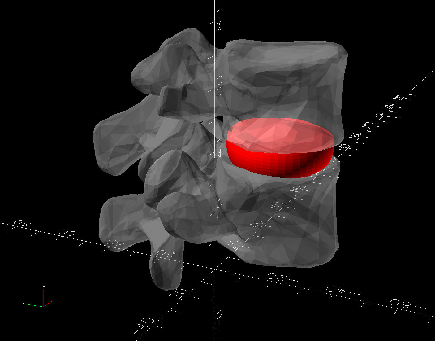
The full-scale L4-L5 vertebrae are from Printables and the ¾ scale L5 is from somewhere I cannot recall. A mother lode of anatomical models is on Thingiverse if you want some 3D printing challenges.
The L4-L5 pair are part of an extensive human anatomic model locating all the pieces at their proper coordinates, so these two hovered about 800 mm above the XY plane. I ran them through the Grid:Tool mesh editor to center them at the XY origin, then put the bottom-most point at Z=0.
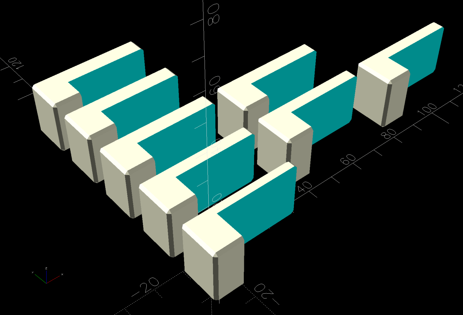
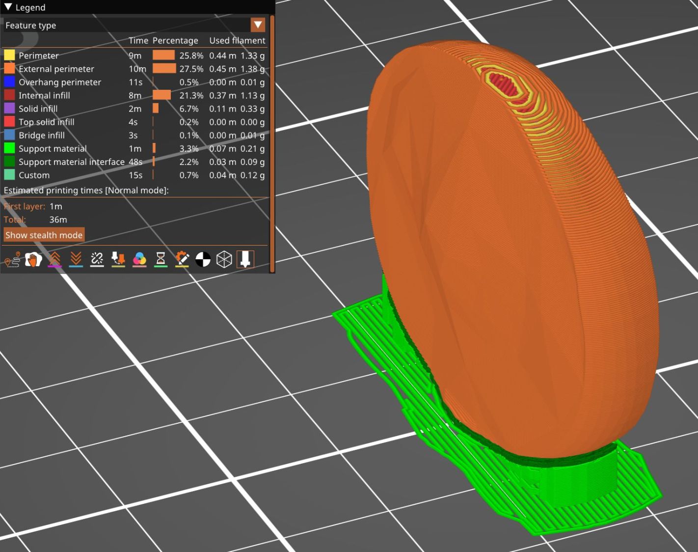
Rotating them individually in PrusaSlicer and painting only the most essential support got them to this state:

Each one take about three hours, so I ran them individually to reduce surface blemishes and maximize the likelihood of happy outcomes. Worked like a champ.
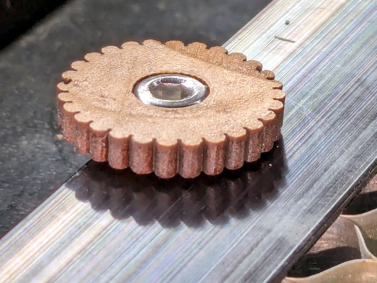
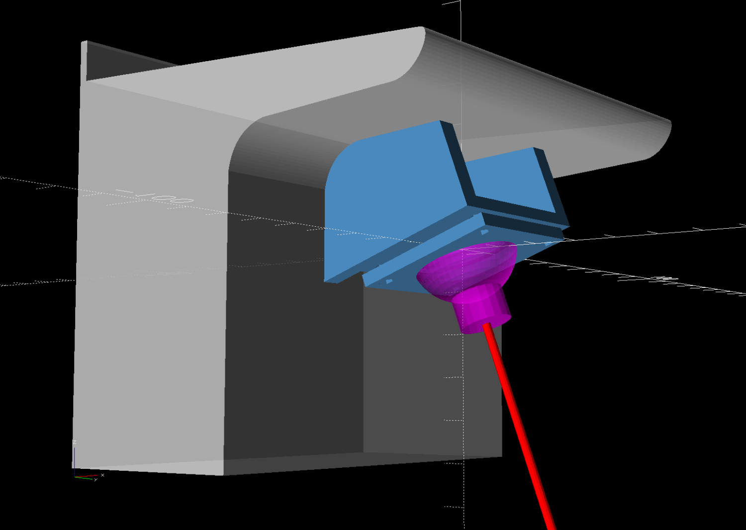
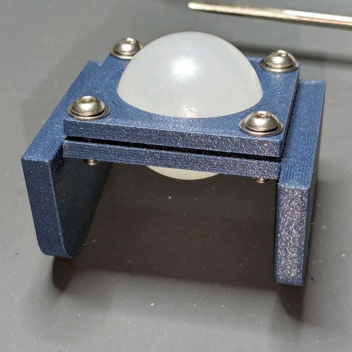
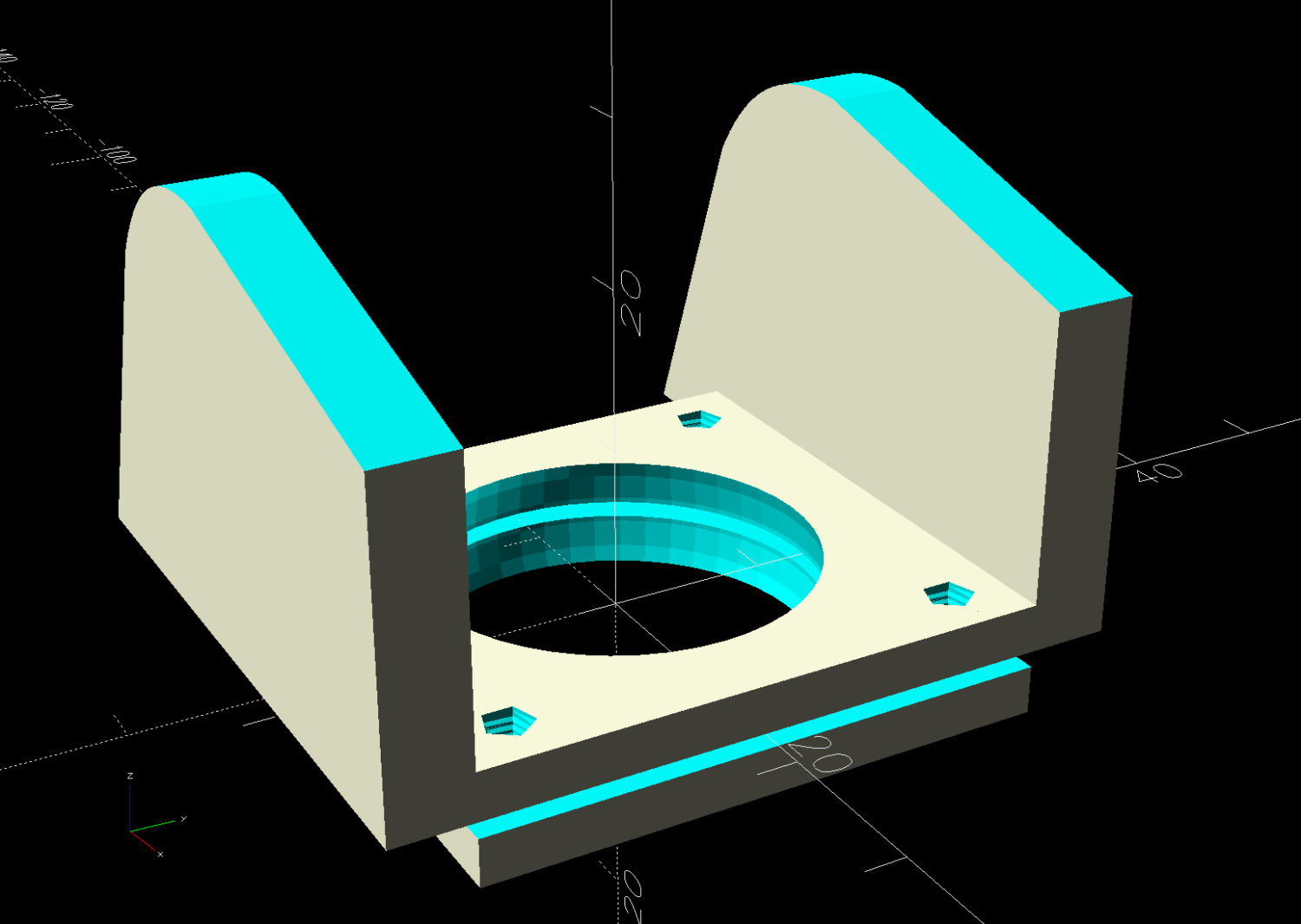
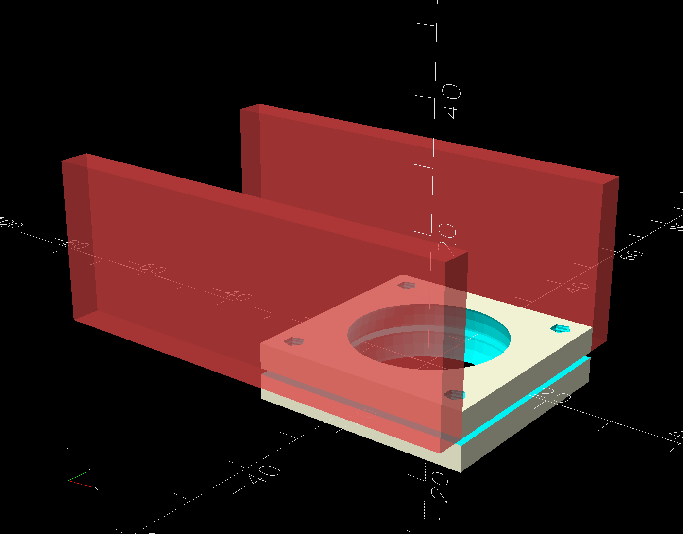
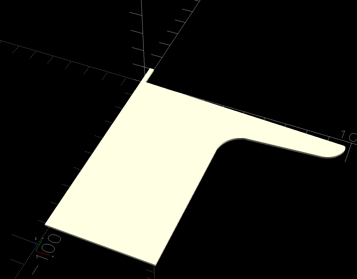
The retina-burn orange disk is not anatomically correct, because the InterWebz apparently does not have a model for spinal cartilage:

Instead, it’s a rounded cylinder resized into an oval, with its top and bottom surfaces formed by subtracting the vertebrae:
The OpenSCAD code doing the heavy lifting:
// Disk between L4 and L5 vertebrae
// Ed Nisley - KE4ZNU
// 2025-03-07

Layout = "Show";    // [Show,Build]

include <BOSL2/std.scad>

module Disk() {
  color("Red")
    difference() {
      translate([9,-18,36])
        rotate(110)
        resize([33,45])
        cyl(d=50,h=14,$fn=48,rounding=7,anchor=BOTTOM);
      import("../Spine/human-spinal-column-including-cervical-thoracic-and-lumbar-vertebra-model_files/L4 L5 vertebrae stacked.stl",
        convexity=10);
    }
}

if (Layout == "Show") {
  Disk();

  color("White",0.3)
      import("../Spine/human-spinal-column-including-cervical-thoracic-and-lumbar-vertebra-model_files/L4 L5 vertebrae stacked.stl",
        convexity=10);

}

if (Layout == "Build") {
  Disk();

}
All of the magic numbers come from eyeballometric measurement & successive approximation.
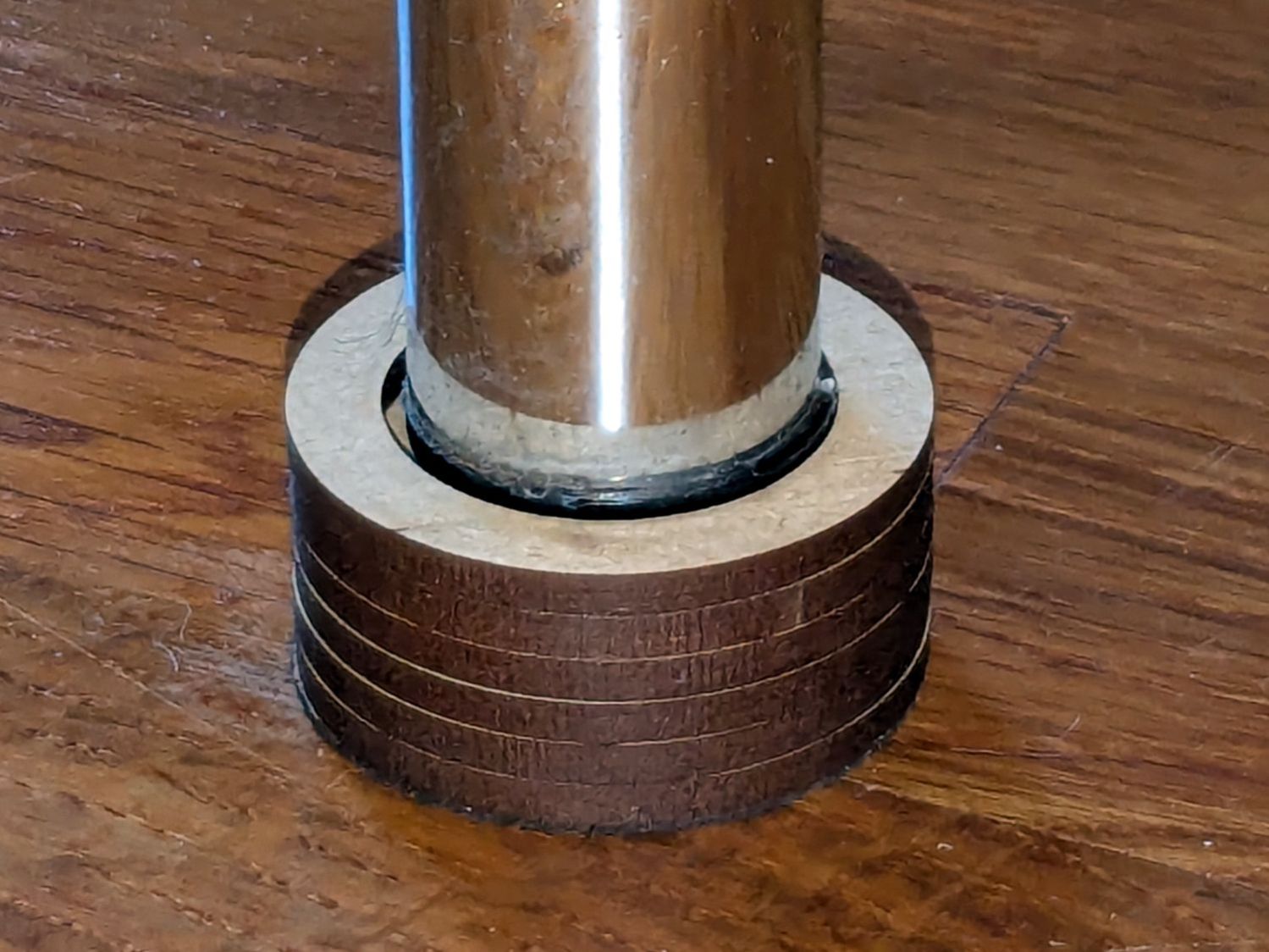
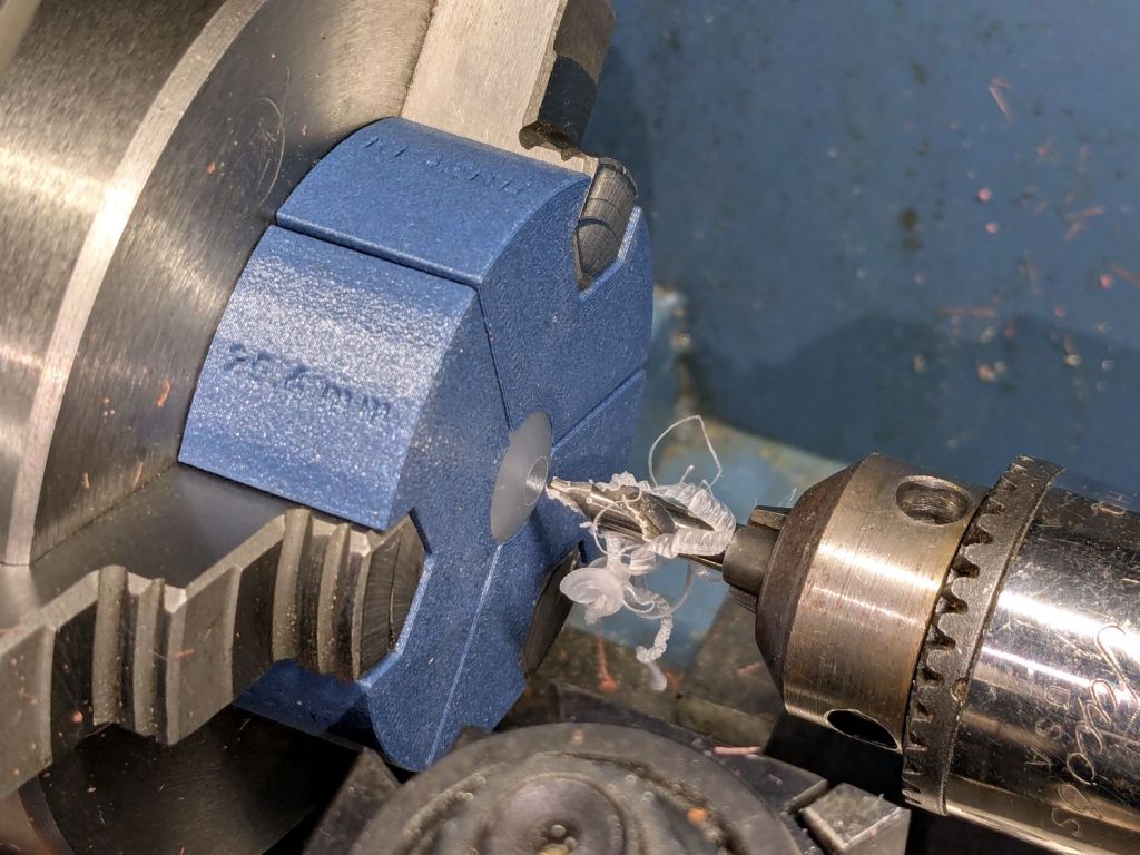
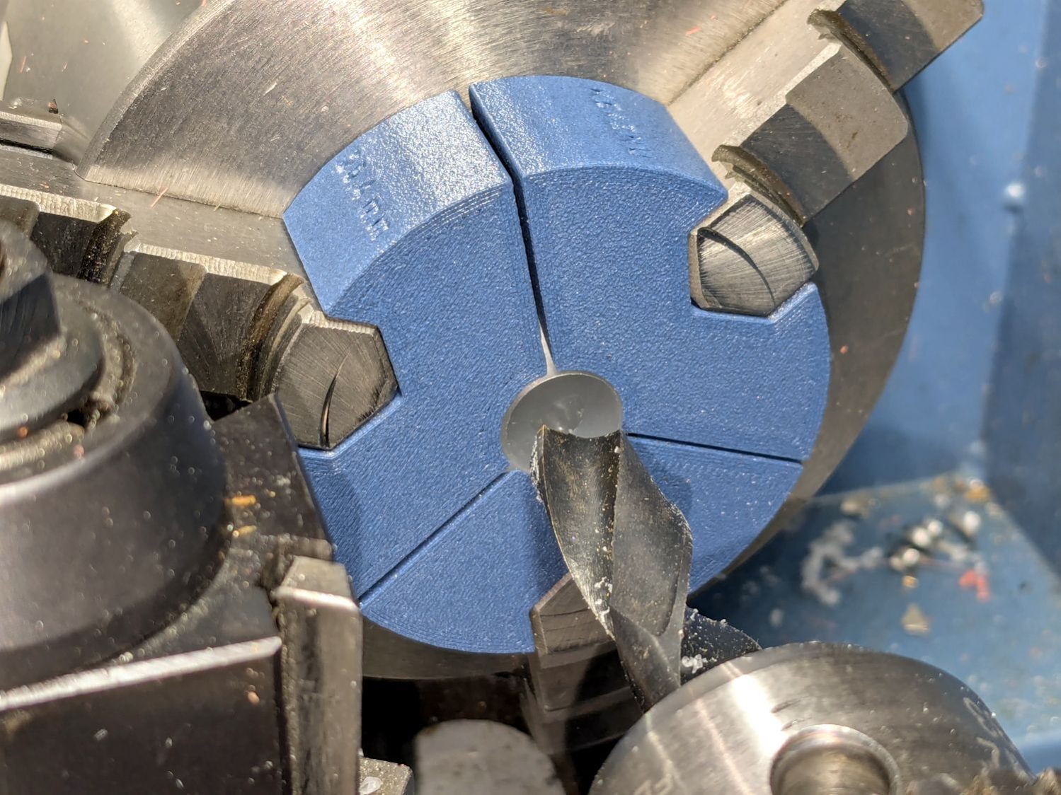
The Build layout left the disk floating in space, whereupon I used PrusaSlicer to reorient it edge-downward on the platform with painted-on support for minimal distortion:
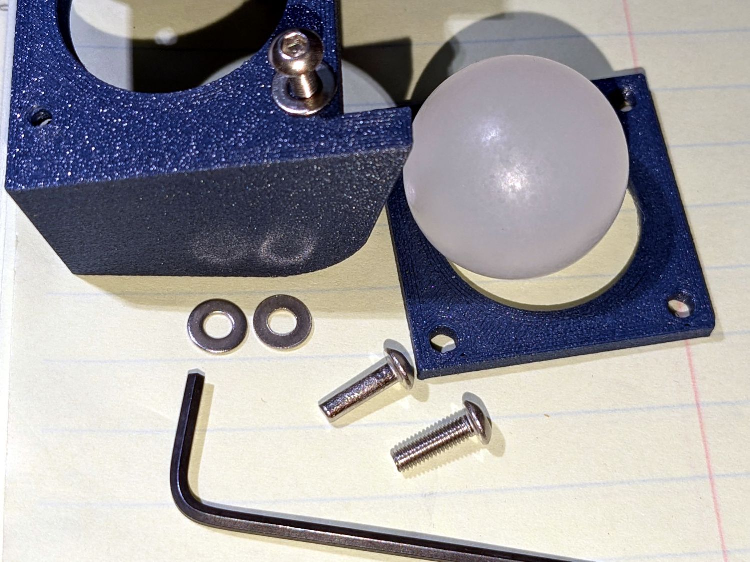
Two dots of E6000+ adhesive hold everything together.
All in all, it was a useful distraction. I’ve been vertically polarized for the last five days and it’s good to be … back.