Ed Nisley's Blog: Shop notes, electronics, firmware, machinery, 3D printing, laser cuttery, and curiosities. Contents: 100% human thinking, 0% AI slop.
Tag: Improvements
Making the world a better place, one piece at a time
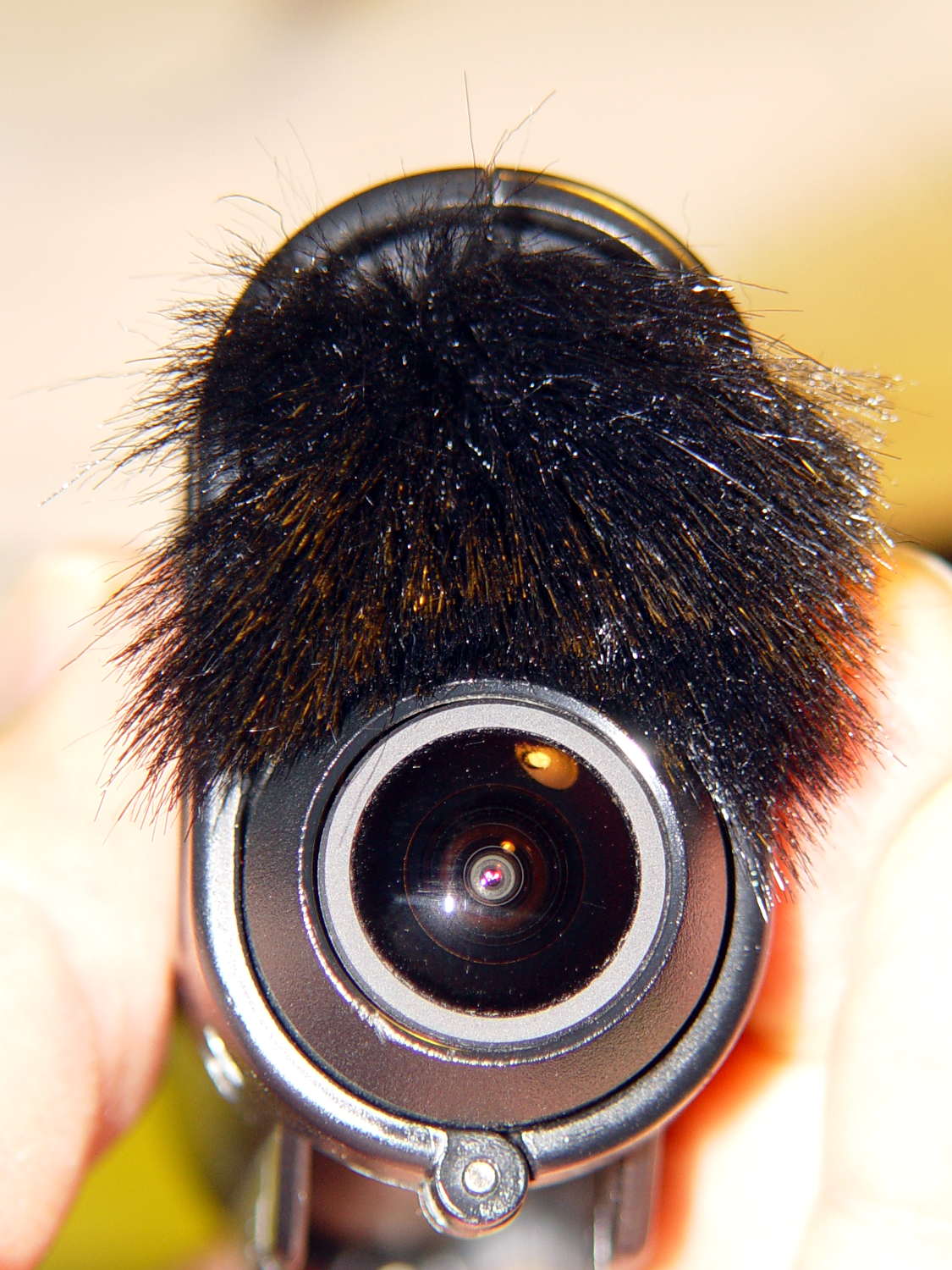
A scrap of fake fur cut to fit the outline of the Sony HDR-AS30V helmet camera and stuck in place with a square of double-stick foam centered above (or below, in the normal orientation) the lens:
Sony HDR-AS30V – fake fur installed
Snippy remarks about what that looks like will not be tolerated, m’kay?
It reduces wind noise to an occasional rumble from strong gusts and even those don’t crush the AGC. My side of our radio conversations became clearly audible, as did shifters clicking and gravel crunching. There’s still plenty of noise, but now it comes from actual sound sources that don’t overwhelm the amp.
A layer of ordinary adhesive tape still covers the mic pores and the fur’s fabric backing extends over the tape, so the combination must muffle the sound at least a little bit. Given the source material and my hearing, it’s Good Enough; Golden Eared Audiophiles need not apply.
I also cannot detect any difference between the left and right audio channels, so the stereo separation at 15 mm isn’t worth much. I don’t know if the camera swaps the audio channels in video flip mode; that would be a nice touch.
The hairs extending outward beside the lens occasionally blew into view, so a haircut is in order:
mah00242-075 – Fake Fur in view
Perhaps a clip that snaps over the skeleton frame to hold a neat patch of fur in place without adhesive on the camera body would be even better?
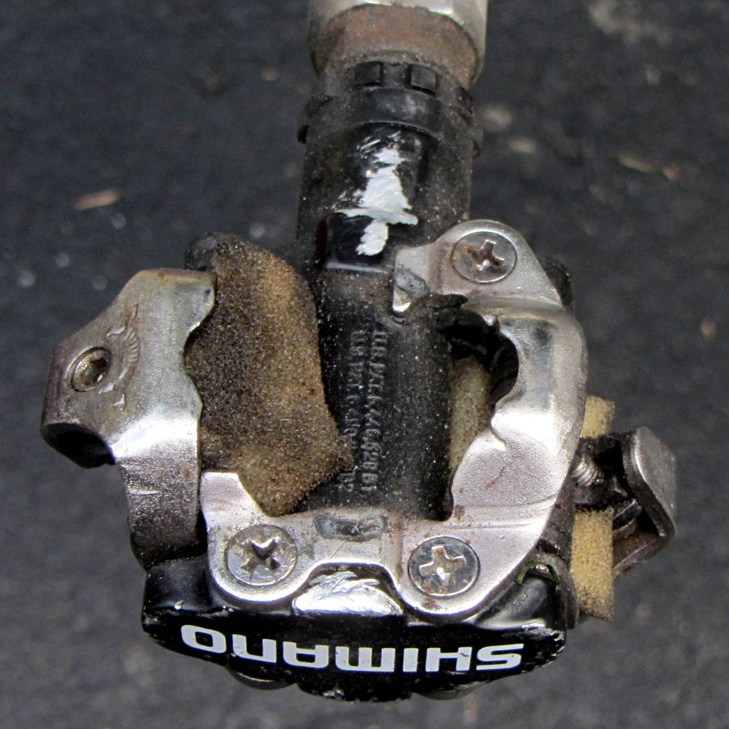
Here’s the solution to creaking SPD pedals due to hardened shoe cleats gritting on hardened pedal latches:
Shimano SPD pedal – cleat oiler
Those are carefully shaped snippets of open-cell foam tucked around the springs under the movable latches, loaded with a few drops of penetrating oil, and ridden for several months. Nary a squeak or grinding sound has emerged: far better than the results after I added a drop of oil whenever either of us heard that sound.
Similar snippets tucked under the forward latch fell out without affecting the results, from which I conclude:
The front latch doesn’t squeak
The foam on the other side is Close Enough
Penetrating oil oozes into a thin film over the whole pedal
The cleats don’t quite touch the ground when we walk, so we’re not leaving oily footprints.
Should I ever install new pedals, I’ll see if a larger foam block can span the gap between the front latch on the top and the movable latch on the bottom.
With the Sony HDR-AS30V in its skeleton frame atop my bike helmet, the audio track for all my rides consists entirely of horrendous wind noise. You can get an idea of the baseline quality from the sound track of a recent Walkway Over The Hudson crossing.
The camera has two mics, although I’m not sure 15 mm of separation really produces meaningful stereo sound:
Sony HDR-AS30V – front view
Note that two of the five pores on each side are closed flat-bottom pits. As with earbud vents , it must be a stylin’ thing.
I added a rounded pad of the same acoustic foam that forms an effective wind noise buffer for the boom mic:
Sony HDR-AS30V – foam mic cover
That reduced the overall noise load by buffering direct wind impact, but non-radio conversations remained unintelligible; there’s just too much low-frequency energy.
Surprisingly, closing the mic pores with ordinary adhesive tape didn’t impair the audio in a quiet room:
Sony HDR-AS30V – closed mic pores
Out on the road that’s even better than foam over open mic pores; I think it reduces the peak volume enough that the internal compression can regain control. Sticking the foam pad over the tape slightly reduced the noise during high-speed (for me, anyhow) parts of the ride, but didn’t make much difference overall.
The wind noise remains too high for comfort, even if I can now hear cleats clicking into pedals, shifters snapping, and even the horrible background music when I’m stopped next to the Mobil gas station on the corner.
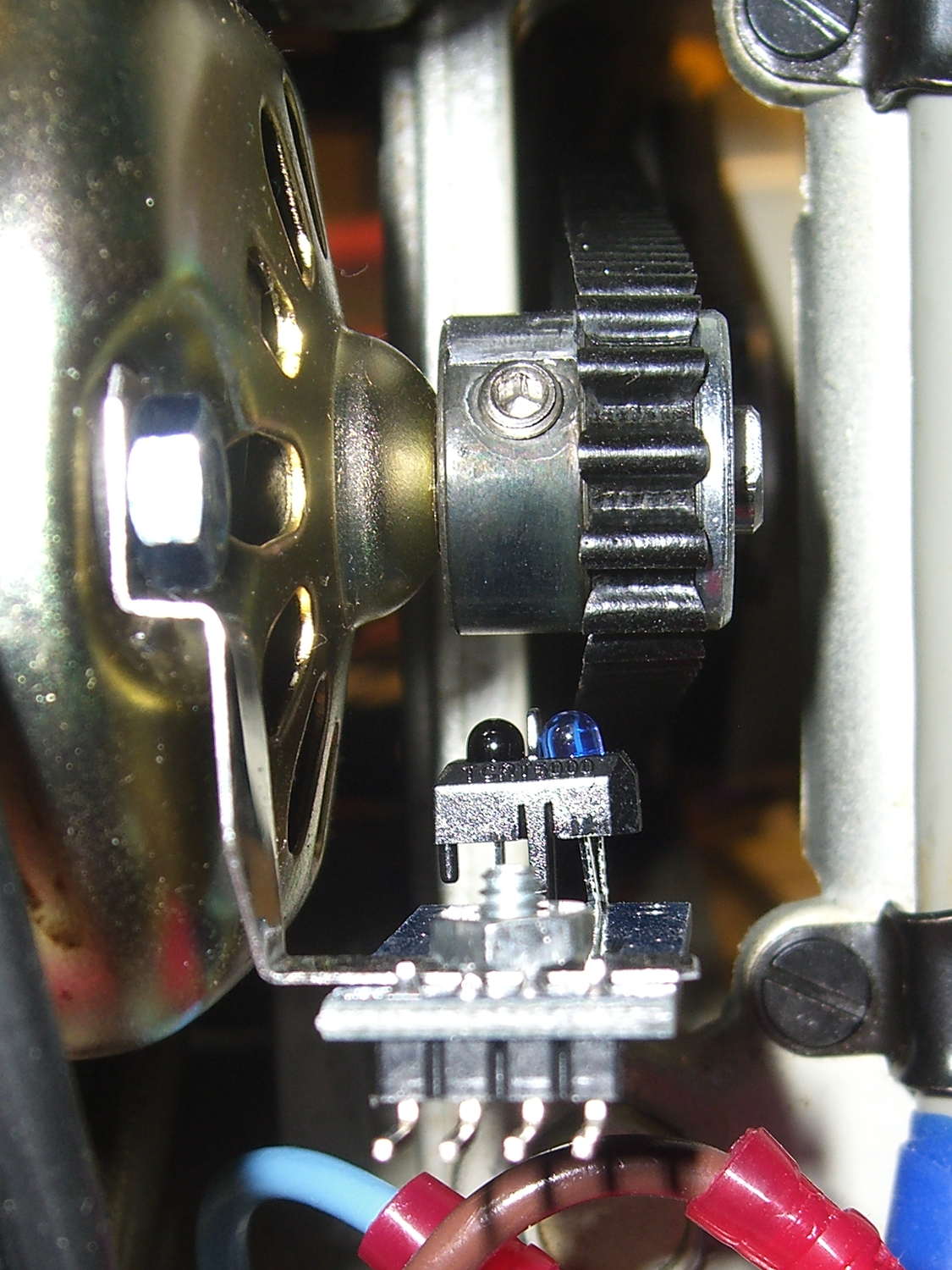
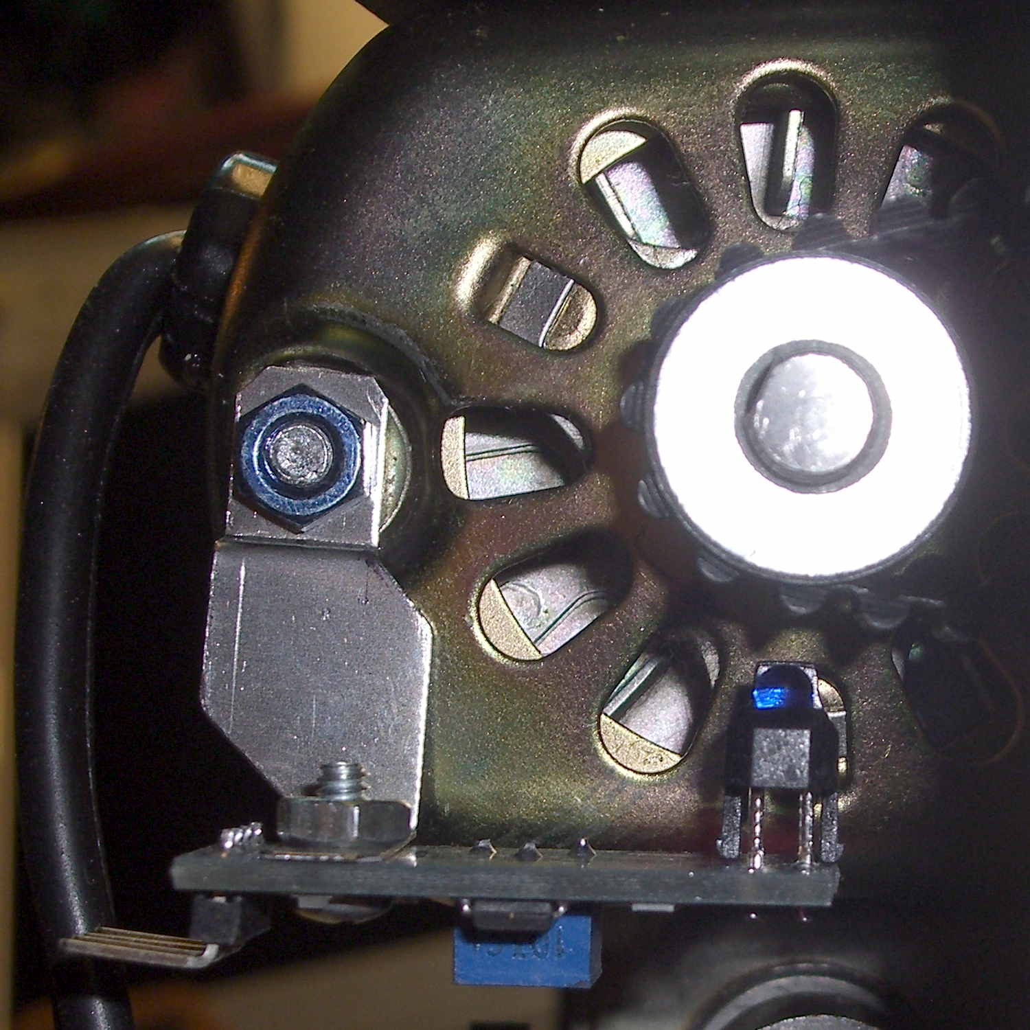
The setscrew in the motor pulley lies directly in the path of the photosensor:
TCTR5000 Motor RPM Sensor – side view
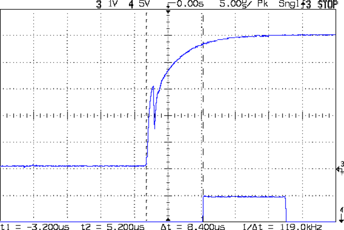
Which produces a glitch in the rising edge of the digital output as the pulley rotates from the dark to the light section:
Motor Sensor – Rising Edge Glitch
The RPM signal goes to Arduino pin D2, where each falling edge triggers an interrupt handler:
const byte PIN_MOTOR_REV = 2;		// DI - IRQ 0 (must be D2)

... snippage...

void setup() {
... snippage ...

    pinMode(PIN_MOTOR_REV,INPUT_PULLUP);
    attachInterrupt((PIN_MOTOR_REV - 2),ISR_Motor,FALLING);			// one IRQ / motor revolution

 ... snippage ...
}
The maximum motor speed is about 11 kRPM, so interrupts should be at least 5.5 ms apart and the digital input should be low. If that’s true, then the code updates a bunch of useful information:
struct pulse_t {
 byte Counter;
 unsigned long TimeThen;
 unsigned long Period;
 word RPM;
 byte State;
};

struct pulse_t Motor;

... snippage ...

//------------------
// ISR to sample motor RPM sensor timing

void ISR_Motor(void) {

static unsigned long Now;

	digitalWrite(PIN_SYNC,HIGH);

	Now = micros();

	if ((5000ul < (Now - Motor.TimeThen)) && !digitalRead(PIN_MOTOR_REV) ) {	// discard glitches
		Motor.Counter++;
		Motor.Period = Now - Motor.TimeThen;
		Motor.TimeThen = Now;
		Motor.State = digitalRead(PIN_MOTOR_REV);		// always zero in a Physics 1 world
	}

	digitalWrite(PIN_SYNC,LOW);
	return;
}
The scope trace shows that the handler takes about 7 µs to get control after the glitch (the left cursor should be on the falling edge, not the rising edge), so the input read occurs when the sensor output is over 4.5 V, causing the handler to discard this spurious interrupt.
Because Motor.Period is a four-byte unsigned long, the Arduino’s CPU must handle it in chunks. Rather than disable interrupts around each use, it’s better to read the value until two successive copies come back identical:
//------------------
// Return current microsecond period without blocking ISR

unsigned long ReadTime(struct pulse_t *pTime) {

unsigned long Sample;

	do {
		Sample = pTime->Period;				// get all four bytes
	} while (Sample != pTime->Period);		//  repeat until not changed by ISR while reading

	pTime->Counter = 0;						// this is a slight race condition

	return Sample;
}
Because the interrupts don’t happen that often, the loop almost always executes only one time. On rare occasions, it’ll go back for another two values.
Converting the pulley rotation period into revolutions per minute goes like this:
Motor.RPM = 60000000ul/ReadTime(&Motor); // one (deglitched) pulse / rev
That’s easier than hiding the setscrew and it also discards any other glitches that may creep into D2…
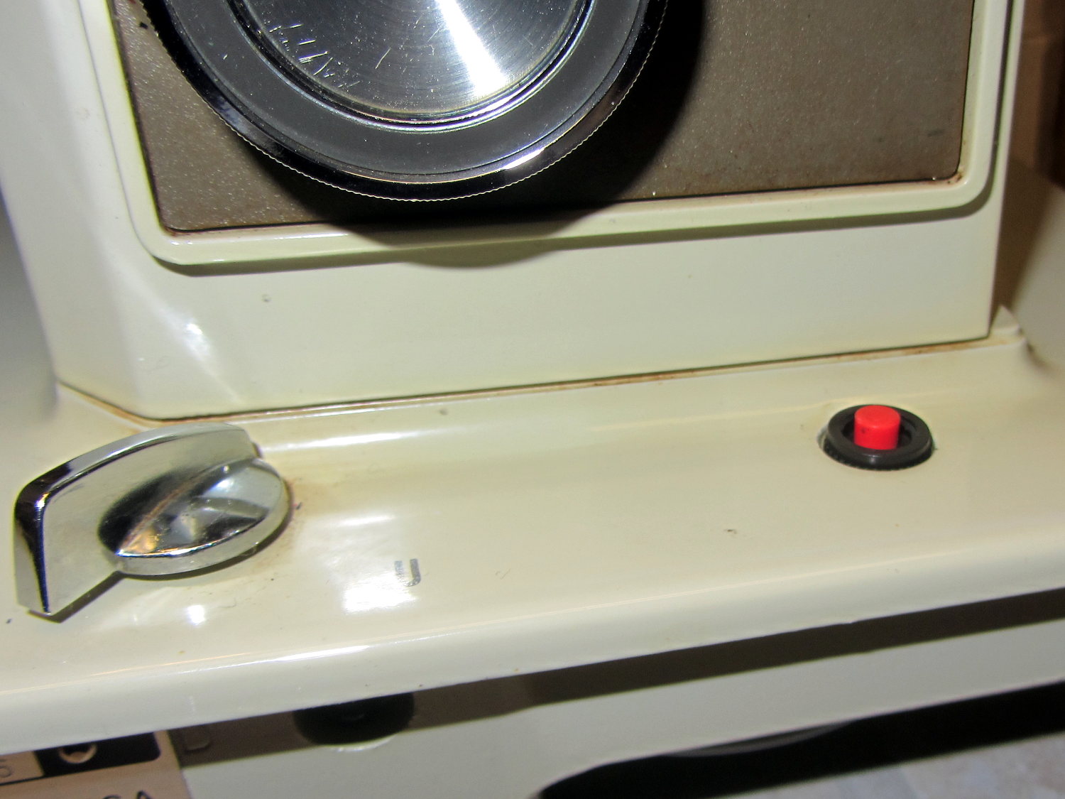
The crash test dummy sewing machine now has a cheerful red momentary pushbutton in the same spot the original machine sported a 120 VAC push-on/push-off power switch:
Kenmore 158 – Digital Power Switch
It’s held in place by a dab of epoxy on the bottom. The threads aren’t quite long enough to engage the ring, so another dab of epoxy holds that in place. In the unlikely event I must replace the button, I’ll deploy a punch and hammer it out from the top; the slick paint on the sides of the straight-sided hole doesn’t provide much griptivity.
The button connects in parallel with the GX270’s front-panel button and the one on the Low Voltage Interface Board, so it operates exactly the same way. My original code didn’t include a delay before turning the power off, which meant that brushing the switch while doing something else would kill the power.
This is not to be tolerated…
You (well, I) must now hold the button down for one second to turn the power off. Releasing it before the deadline has no effect, other than blinking the green power LED on the front panel a few times.
The routine maintains a timer that allows it to yield control to the mainline code, rather than depend on a blocking timer that would screw up anything else that’s in progress:
//------------------
// Handle shutdown timing when power button closes
// Called every time around the main loop

void TestShutdown(void) {

	if (LOW == digitalRead(PIN_BUTTON_SENSE)) {			// power button pressed?
		if (ShutdownPending) {
			if (1000ul < (millis() - ShutdownPending)) {
				printf("Power going off!\r\n");
				digitalWrite(PIN_ENABLE_AC,LOW);
				digitalWrite(PIN_ENABLE_ATX,LOW);
				while(true) {
					delay(20);
					TogglePin(PIN_PWR_G);				// show we have shut down
				}
			}
		}
		else {
			ShutdownPending = millis();					// record button press time
			printf("Shutdown pending...\r\n");
		}
	}
	else {
		if (ShutdownPending) {
			ShutdownPending = 0ul;						// glitch or button released
			printf("Shutdown cancelled\r\n");
		}
	}
}
The normal Arduino bootloader imposes a similar delay while turning the power on, which means that you can’t accidentally light the machine up by bumping the switch. All in all, it’s much more user-friendly this way.
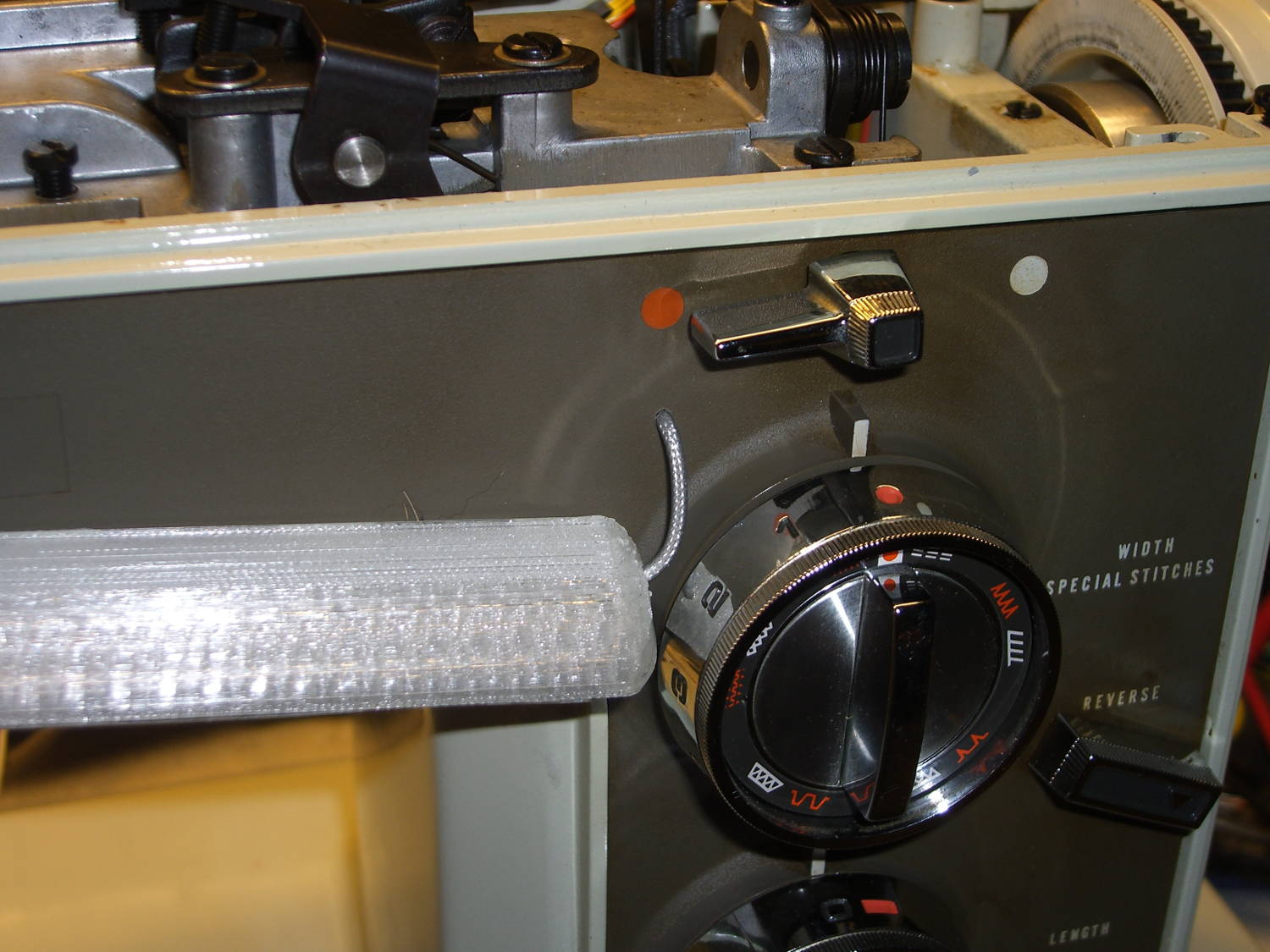
It Has Been Decided (in that place where what is decided must be) to allow a single hole in the sewing machine’s front panel:
Kenmore 158 – Front LED strip – wire routing
The hole barely passes the 2 mm coaxial cable I’m misusing for the LED strips and is located where it:
Clears the machine’s metal frame to the upper left
Isn’t blocked by the knob’s mounting bracket to the lower right
Doesn’t snag the knob’s cam followers all over the insides
Lines up directly below the orange dot for pretty
The first three of those happen behind the front panel, inside the frame, where you (well, I) can neither see nor measure the locations. I used a large outside caliper to get a feel for where the hole could possibly fit, then got it right on the first try!
On the rear panel, it turns out that the presser foot lever doesn’t quite touch the top of its slot in the frame, so the cable for those LED strips can sneak through:
Kenmore 158 – Rear LED strips – wire routing
Just inside that slot, the cable turns right, passes into the endcap, then goes upward to re-emerge at the top, inside the channel used for the old 120 VAC zip cord that powered the incandescent bulb in the endcap.
I had some square cable clips lying around, so I used them, but the (yet to be designed) round versions will look better.
The grody frame tells you this is the crash test dummy machine I’m using to verify things before installing them in Mary’s machine.
The improved cable routing required different hole positions in the LED strip mounts:
Strip Light Mount – Drilled cable routing
The internal wire route follows the original 120 VAC zip cord’s route from the bottom of the machine to the endcap (on the left), with the new branch for the front LEDs curving over the main shaft:
Kenmore 158 – LED strips – internal wire routing
The four-conductor ribbon cable also carries the supply voltage for the yet-to-be-built high intensity LED emitters in the end cap that will replace the 10 mm LEDs, with the ends terminated under the clamp in the middle. Those old steel wire clamps seem grossly oversized for the job, but that’s OK with me.
The ribbon cable eases past that whirling crank arm, then passes through the frame to the outside cover under the handwheel, where it just barely clears the drive belts. A few zip ties hold it out of the way.
The OpenSCAD source code offsets the wiring holes by 0.5 mm from the ends of the LED strips for easier wire bending, but is otherwise pretty much the same as before:
// LED Strip Lighting Brackets for Kenmore Model 158 Sewing Machine
// Ed Nisley - KE4ZNU - March 2014
//  October 2014 - tweak endcap length & channel position

Layout = "Build";			// Build Show Channels Strip

//- Extrusion parameters must match reality!
//  Print with 2 shells and 3 solid layers

ThreadThick = 0.20;
ThreadWidth = 0.40;

HoleWindage = 0.2;			// extra clearance

Protrusion = 0.1;			// make holes end cleanly

AlignPinOD = 1.70;			// assembly alignment pins: filament dia

inch = 25.4;

function IntegerMultiple(Size,Unit) = Unit * ceil(Size / Unit);

//----------------------
// Dimensions

LEDSegment = [25.0,10.0,3.0];		//  size of each LED segment
SEGLENGTH = 0;
SEGWIDTH = 1;
SEGHEIGHT = 2;

WireChannel = 3.0;				// wire routing channel diameter

StripHeight = 12.0;				// sticky tape width

DefaultLayout = [1,2,"Wire","NoWire"];
NUMSEGS = 0;
NUMSTRIPS = 1;
WIRELEFT = 2;
WIRERIGHT = 3;

EndCapSides = 8*4;				// endcap smoothness
EndCapShim = 0.5;				// additional space for easier wire bending

function EndCapSize(Layout) = [(2*WireChannel + EndCapShim),Layout[NUMSTRIPS]*LEDSegment[SEGWIDTH],StripHeight];

//----------------------
// Useful routines

module PolyCyl(Dia,Height,ForceSides=0) {			// based on nophead's polyholes

  Sides = (ForceSides != 0) ? ForceSides : (ceil(Dia) + 2);

  FixDia = Dia / cos(180/Sides);

  cylinder(r=(FixDia + HoleWindage)/2,
           h=Height,
           $fn=Sides);
}

module ShowPegGrid(Space = 10.0,Size = 1.0) {

  RangeX = floor(100 / Space);
  RangeY = floor(125 / Space);

	for (x=[-RangeX:RangeX])
	  for (y=[-RangeY:RangeY])
		translate([x*Space,y*Space,Size/2])
		  %cube(Size,center=true);

}

//-- The negative space used to thread wires into the endcap

module MakeWireChannel(Layout = DefaultLayout,Which = "Left") {

	EndCap = EndCapSize(Layout);	// radii of end cap spheroid

	HalfSpace = EndCap[0] * ((Which == "Left") ? 1 : -1);

	render(convexity=2)
	translate([0,LEDSegment[SEGWIDTH]/2,0])
		intersection() {
			union() {
				cube([2*WireChannel,WireChannel,EndCap[2]],center=true);
				translate([-2*EndCap[0],0,EndCap[2]/2])
					rotate([0,90,0]) rotate(180/6)
						PolyCyl(WireChannel,4*EndCap[0],6);
			}
			translate([HalfSpace,0,(EndCap[2] - Protrusion)]) {
				cube(2*EndCap,center=true);
			}
		}
}

//-- The whole strip, minus wiring channels

module MakeStrip(Layout = DefaultLayout) {

	EndCap = EndCapSize(Layout);	// radii of end cap spheroid

	BarLength = Layout[NUMSEGS] * LEDSegment[SEGLENGTH];				// central bar length

	echo(str("Strip OAL: ",BarLength + 2*EndCap[SEGLENGTH]));

	hull()
		difference() {
			for (x = [-1,1])						// endcaps as spheroids
				translate([x*BarLength/2,0,0])
					resize(2*EndCap) rotate([0,90,0]) sphere(1.0,$fn=EndCapSides);
			translate([0,0,-EndCap[2]])
				cube([2*BarLength,3*EndCap[1],2*EndCap[2]],center=true);
			translate([0,-EndCap[1],0])
				cube([2*BarLength,2*EndCap[1],3*EndCap[2]],center=true);
		}

}

//-- Cut wiring channels out of strip

module MakeMount(Layout = DefaultLayout) {

	BarLength = Layout[NUMSEGS] * LEDSegment[SEGLENGTH];

	difference() {
		MakeStrip(Layout);
		if (Layout[WIRELEFT] == "Wire")
			translate([(BarLength/2 + EndCapShim),0,0])
				MakeWireChannel(Layout,"Left");
		if (Layout[WIRERIGHT] == "Wire")
			translate([-(BarLength/2 + EndCapShim),0,0])
				MakeWireChannel(Layout,"Right");
	}
}

//- Build it

ShowPegGrid();

if (Layout == "Channels") {
	translate([ (2*WireChannel + 1.0),0,0]) MakeWireChannel(DefaultLayout,"Left");
	translate([-(2*WireChannel + 1.0),0,0]) MakeWireChannel(DefaultLayout,"Right");
}

if (Layout == "Strip") {
	MakeStrip(DefaultLayout);
}

if (Layout == "Show") {
	MakeMount(DefaultLayout);
}

if (Layout == "Build") {

	if (false) {					// original no-drill wiring
		translate([0,(3*LEDSegment[SEGWIDTH]),0]) MakeMount([1,2,"Wire","Wire"]);		// rear left side, vertical
		translate([0,0,0]) MakeMount([5,2,"Wire","NoWire"]);				// rear top, across arm
		translate([0,-(3*LEDSegment[SEGWIDTH]),0]) MakeMount([6,2,"NoWire","Wire"]);	// front top, across arm
	}

	if (true) {						// front: drill panel, rear: route through foot lift lever
		translate([0,(3*LEDSegment[SEGWIDTH]),0])
			MakeMount([1,2,"NoWire","Wire"]);				// rear left side, vertical
		translate([0,0,0])
			MakeMount([5,2,"Wire","Wire"]);					// rear top, across arm
		translate([0,-(1*LEDSegment[SEGWIDTH]),0])
			rotate(180)
			MakeMount([6,2,"NoWire","Wire"]);				// front top, across arm
	}
}
The first sensor bracket came from the scrap pile, but showed that it would produce 1/rev pulses from the motor shaft pulley. The positioning wasn’t quite right, so I made another bracket that put the TCRT5000 sensor at right angles to the pulley:
TCTR5000 Motor RPM Sensor – end view
All of the sensors have a rakish tilt over their PCB, so at some point I must resolder them:
TCTR5000 Motor RPM Sensor – side view
It might not matter, as the phototransistor on the left peers directly at the pulley, with the LED on the right acting as a floodlight.
“Made another bracket” sounds like the metal sprang fully formed from the concept. Herewith, the early contestants atop a sketch and the flat layout for The Ultimate Bracket:
Motor RPM Sensor Brackets
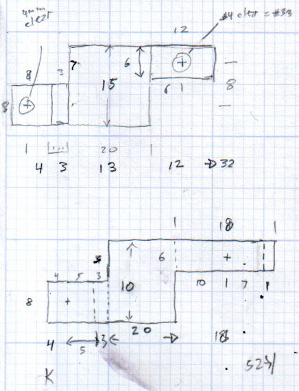
A closer look at that final dimension sketch, because I’ll need it again:
RPM Bracket Dimensions
The vertical size of the center section (12 mm) sets the perpendicular distance of the sensor from the shaft. The horizontal size (14 mm) controls the pulley-to-sensor spacing.
The horizontal distance from the center section to the hole on the right (10 mm) adjusts the sensor spacing parallel to the shaft.
I cut the overall rectangle with tin snips, drilled & cleaned the holes, applied a nibbling tool to the details, trimmed the corners, filed off sharp edges & spines, and it was all good.
The doodles for the first few attempts, as I don’t want to repeat those mistakes:
Bracket Doodles
All in all, a few more hours of Quality Shop Time than I expected…