Mary asked for a less angular version of the Lip Balm Holder, which gave me a chance to practice my list comprehension:

You hand the OpenSCAD program a list of desired tube diameters in the order you want them, the program plunks the first one (ideally, the largest diameter) in the middle, arranges the others around it counterclockwise from left to right, then slips a lilypad under each tube.
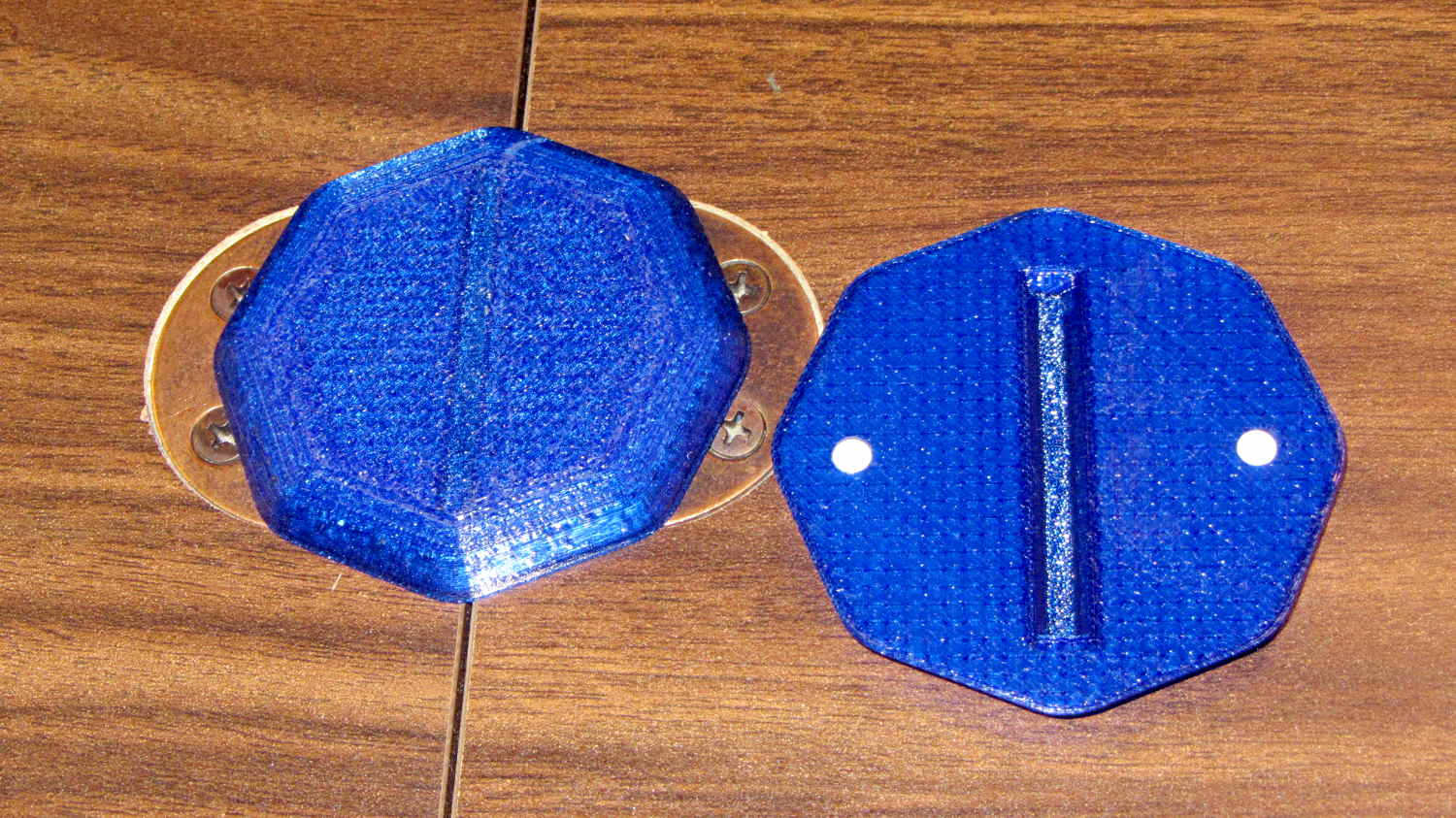
As long as you don’t ask for anything egregiously stupid, the results look reasonably good:
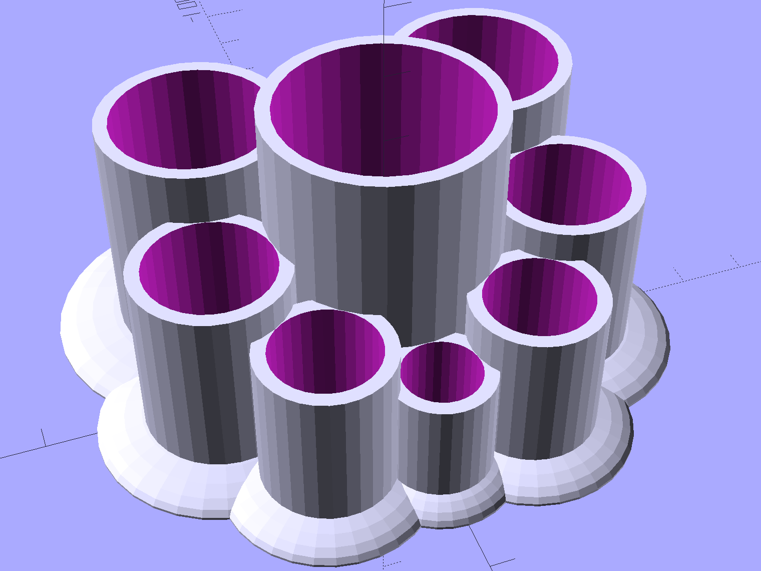
As before, each tube length is 1.5 times its diameter; the lipsticks / balms fit loosely and don’t flop around.
Given the tube diameters and the wall thickness, list comprehensions simplify creating lists of the radii from the center tube to each surrounding tube, the center-to-center distances between each of the outer tubes, and the angles between successive tubes:
// per-tube info, first element forced to 0 to make entries match RawDia vector indexes

Radius = [0, for (i=[1:NumTubes-1]) (TubeRad[0] + TubeRad[i] + Wall)];			// Tube[i] distance to center pointRadius = [0, for (i=[1:NumTubes-1]) (TubeRad[0] + TubeRad[i] + Wall)];			// Tube[i] distance to center point
echo(str("Radius: ",Radius));

CtrToCtr = [0, for (i=[1:NumTubes-2]) (TubeRad[i] + TubeRad[i+1] + Wall)];		// Tube[i] distance to Tube[i+1]
echo(str("CtrToCtr: ",CtrToCtr));

Angle = [0, for (i=[1:NumTubes-2]) acos((pow(Radius[i],2) + pow(Radius[i+1],2) - pow(CtrToCtr[i],2)) / (2 * Radius[i] * Radius[i+1]))];
echo(str("Angle: ",Angle));

TotalAngle = sumv(Angle,len(Angle)-1);
echo(str("TotalAngle: ",TotalAngle));
The angles come from the oblique triangle solution when you know all three sides (abc) and want the angle (C) between a and b:
C = arccos( (a2 + b2 - c2) / (2ab) )
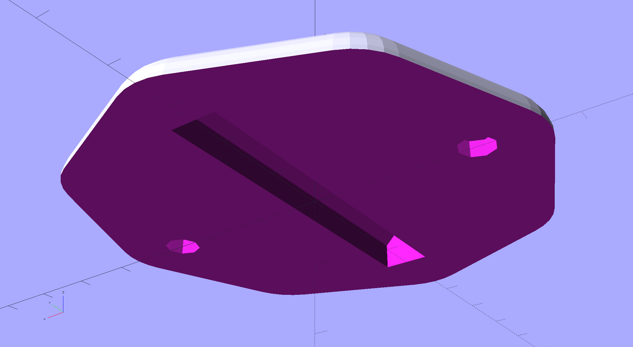
Peering down inside, the Slic3r preview shows the lily pads are the tops of squashed spheres:
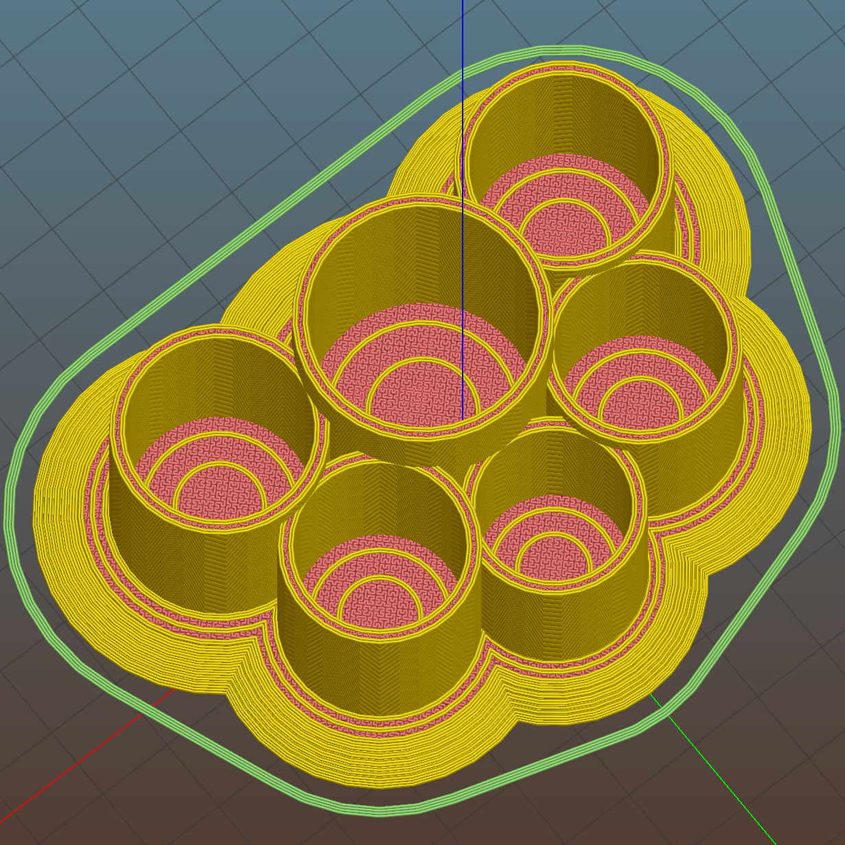
The pads are 2.0 times the tube diameter, which seemed most pleasing to the eye. They top out at 2.0 mm thick, which might make the edges too thin for comfort.
Update: Here’s what it looks like with a convex hull wrapped around all the lilypads:
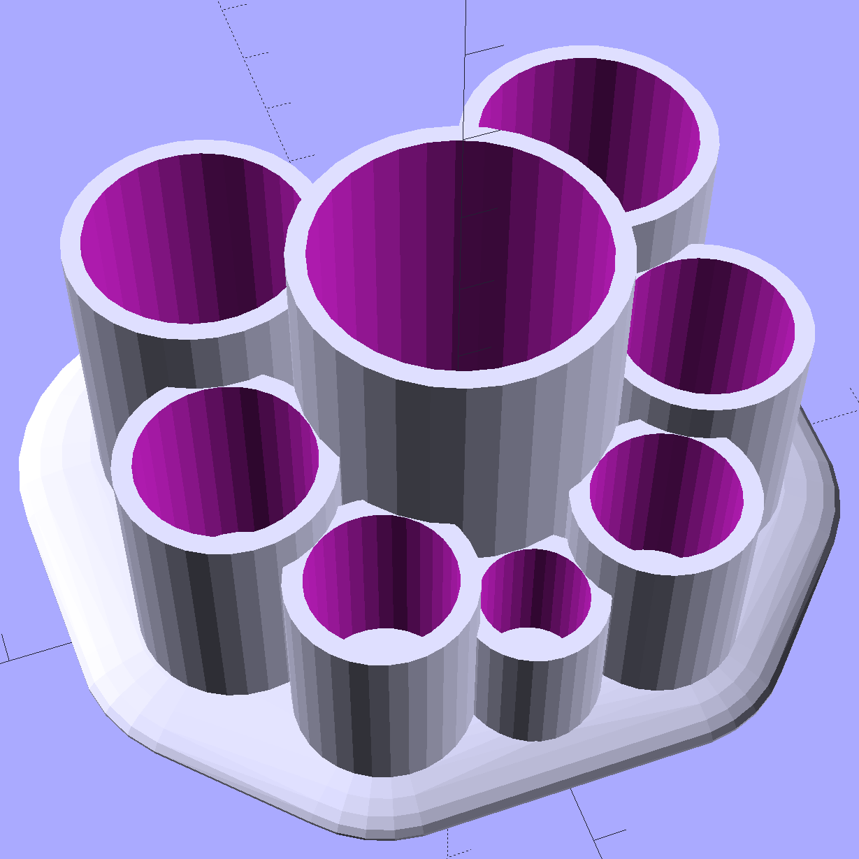
I’m awaiting reports from My Spies concerning the typical diameter(s) of lipstick tubes, then I’ll run off a prototype and see about the lily pad edges.
The OpenSCAD source code as a GitHub gist:
| // Lipstick and Balm Tube Holder | |
| // Ed Nisley KE4ZNU – February 2016 | |
| //- Extrusion parameters – must match reality! | |
| ThreadThick = 0.25; | |
| ThreadWidth = 0.40; | |
| function IntegerMultiple(Size,Unit) = Unit * ceil(Size / Unit); | |
| Protrusion = 0.1; | |
| HoleWindage = 0.2; | |
| //—— | |
| // Dimensions | |
| RawDia = [26,21,19,17,19,21]; // actual tube diameters in desired order, center = largest first | |
| NumTubes = len(RawDia); | |
| Clearance = 2.0; | |
| TubeDia = [for (i=[0:NumTubes-1]) (RawDia[i] + Clearance)]; // actual tube diameters | |
| TubeRad = TubeDia / 2; | |
| echo(str("NumTubes: ",NumTubes)); | |
| Wall = 2.0; | |
| BaseThick = 2.0; | |
| BaseFactor = 2.0; | |
| NumSides = 8*4; | |
| // per-tube info, first element forced to 0 to make entries match RawDia vector indexes | |
| Radius = [0, for (i=[1:NumTubes-1]) (TubeRad[0] + TubeRad[i] + Wall)]; // Tube[i] distance to center point | |
| echo(str("Radius: ",Radius)); | |
| CtrToCtr = [0, for (i=[1:NumTubes-2]) (TubeRad[i] + TubeRad[i+1] + Wall)]; // Tube[i] distance to Tube[i+1] | |
| echo(str("CtrToCtr: ",CtrToCtr)); | |
| Angle = [0, for (i=[1:NumTubes-2]) acos((pow(Radius[i],2) + pow(Radius[i+1],2) – pow(CtrToCtr[i],2)) / (2 * Radius[i] * Radius[i+1]))]; | |
| echo(str("Angle: ",Angle)); | |
| TotalAngle = sumv(Angle,len(Angle)-1); | |
| echo(str("TotalAngle: ",TotalAngle)); | |
| //———————- | |
| // Useful routines | |
| // vector sum cribbed from doc | |
| function sumv(v,i,s=0) = (i==s ? v[i] : v[i] + sumv(v,i-1,s)); | |
| //———————- | |
| //- Build it | |
| for (i=[0:NumTubes-1]) | |
| rotate(90 – TotalAngle/2 + sumv(Angle, (i>0) ? (i-1) : 0)) | |
| translate([Radius[i],0,0]) { | |
| resize([0,0,2*BaseThick]) // bases | |
| difference() { | |
| sphere(r=BaseFactor*TubeRad[i],$fn=NumSides); | |
| translate([0,0,-BaseFactor*TubeDia[i]]) | |
| cube(2*BaseFactor*TubeDia[i],center=true); | |
| } | |
| difference() { // tubes | |
| cylinder(r=TubeRad[i] + Wall,h=1.5*TubeDia[i] + BaseThick,$fn=NumSides); | |
| cylinder(d=TubeDia[i],h=1.5*TubeDia[i] + BaseThick + Protrusion,$fn=NumSides); | |
| } | |
| } | |