The Smell of Molten Projects in the Morning

Ed Nisley's Blog: Shop notes, electronics, firmware, machinery, 3D printing, laser cuttery, and curiosities. Contents: 100% human thinking, 0% AI slop.

Tag: Improvements

Making the world a better place, one piece at a time

  • Mini-Lathe: Adjusting the Carriage Retaining Strips

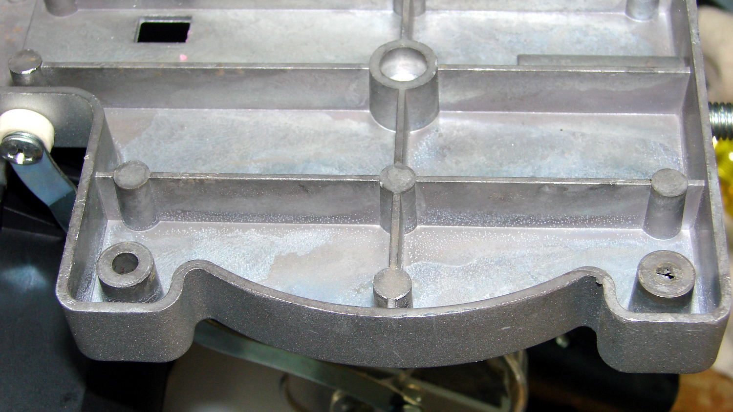
    The mini-lathe carriage rides on its craptastically finished ways, with a pair of steel strips holding it in place. They’re supposed to be flat against the bed, with a nice oil layer providing a slippery surface. Well, apart from lots and lots of oil, that’s not their as-delivered condition:
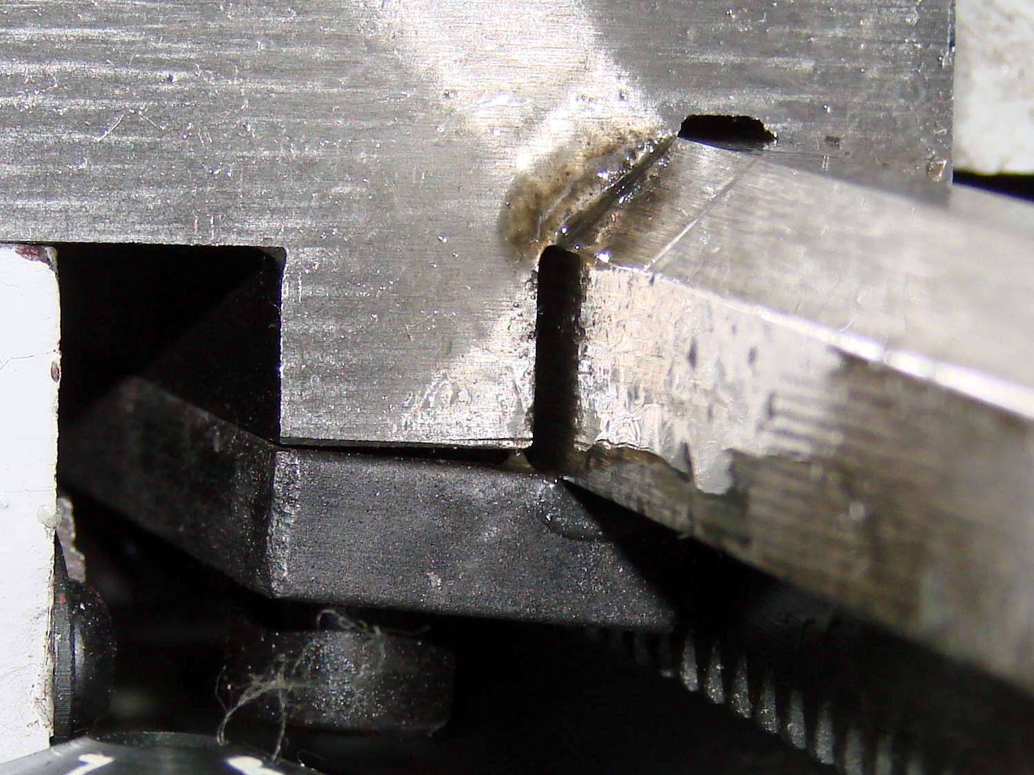
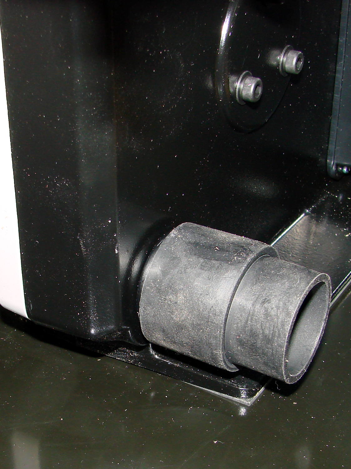
    LMS Mini-lathe - carriage front retainer - as received
    LMS Mini-lathe – carriage front retainer – as received

    The rear retainer:

    LMS Mini-lathe - carriage rear retainer - as received
    LMS Mini-lathe – carriage rear retainer – as received

    Adjusting both retaining strips works best without the apron in place, which works best without the leadscrew in place, which requires dismantling the change gear quadrant and messing around with the pieces. Instead, disengage the half nuts (which is how they should be, anyway), remove the two big apron screws, then gently maneuver the apron out of the way off to the right. It’ll rest against the chip pan and hang from the half nuts, but won’t get into any trouble unless you do something stupid.

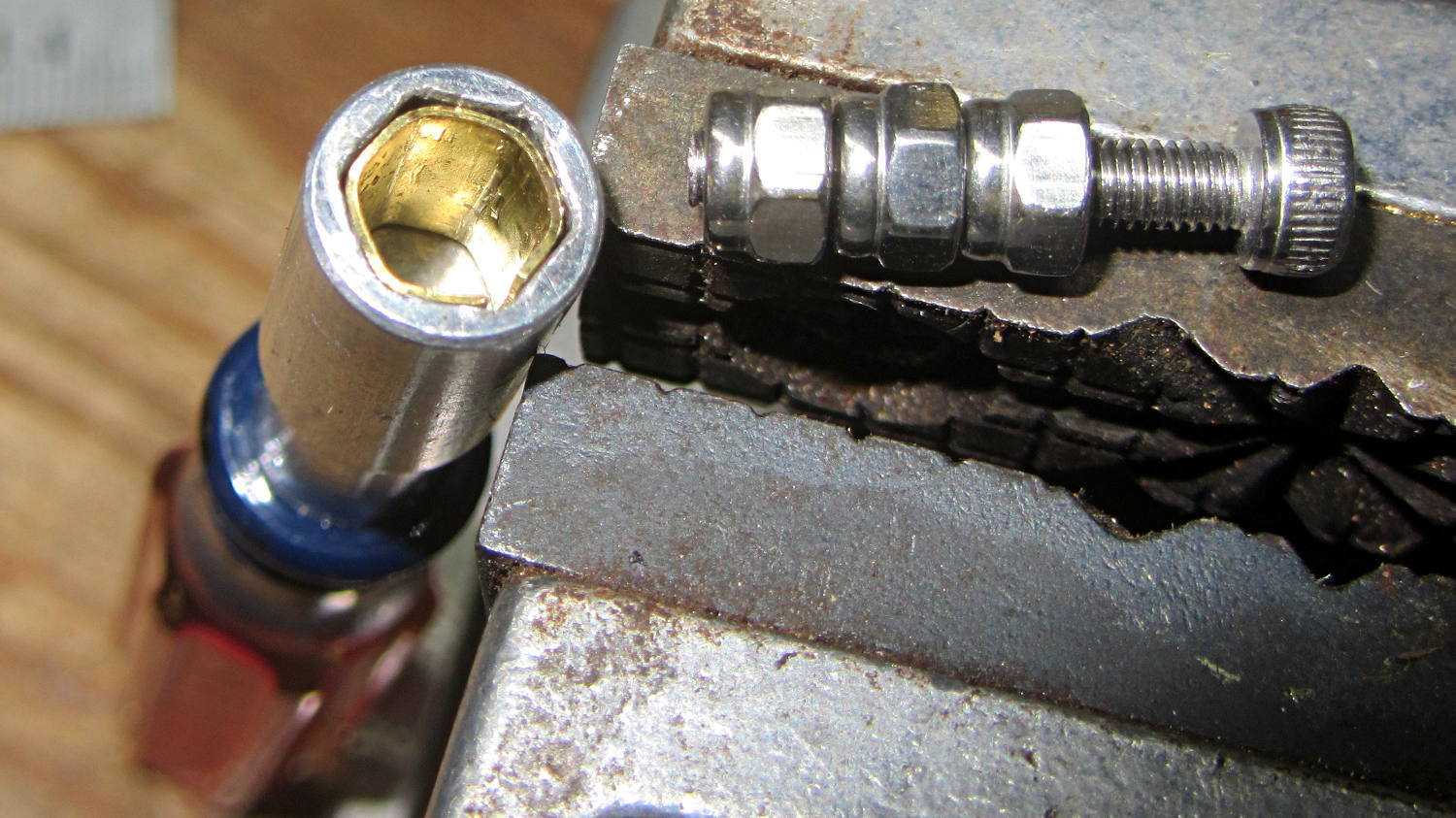
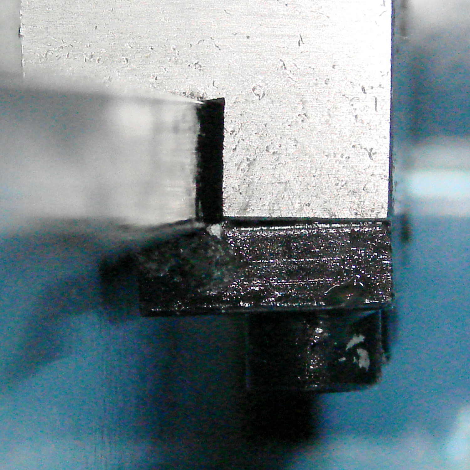
    Remove both strips, wipe off the excess oil, then align each strip in turn:

    Clamp the strip in place to ensure it’s flat against the underside of the bed way:

    LMS Mini-lathe - carriage front retainer - clamped
    LMS Mini-lathe – carriage front retainer – clamped

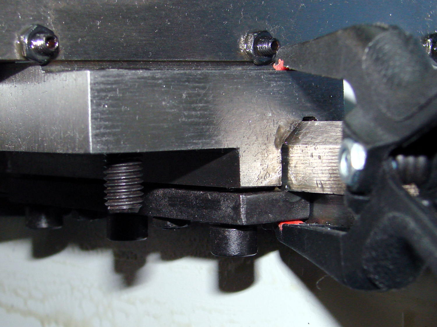
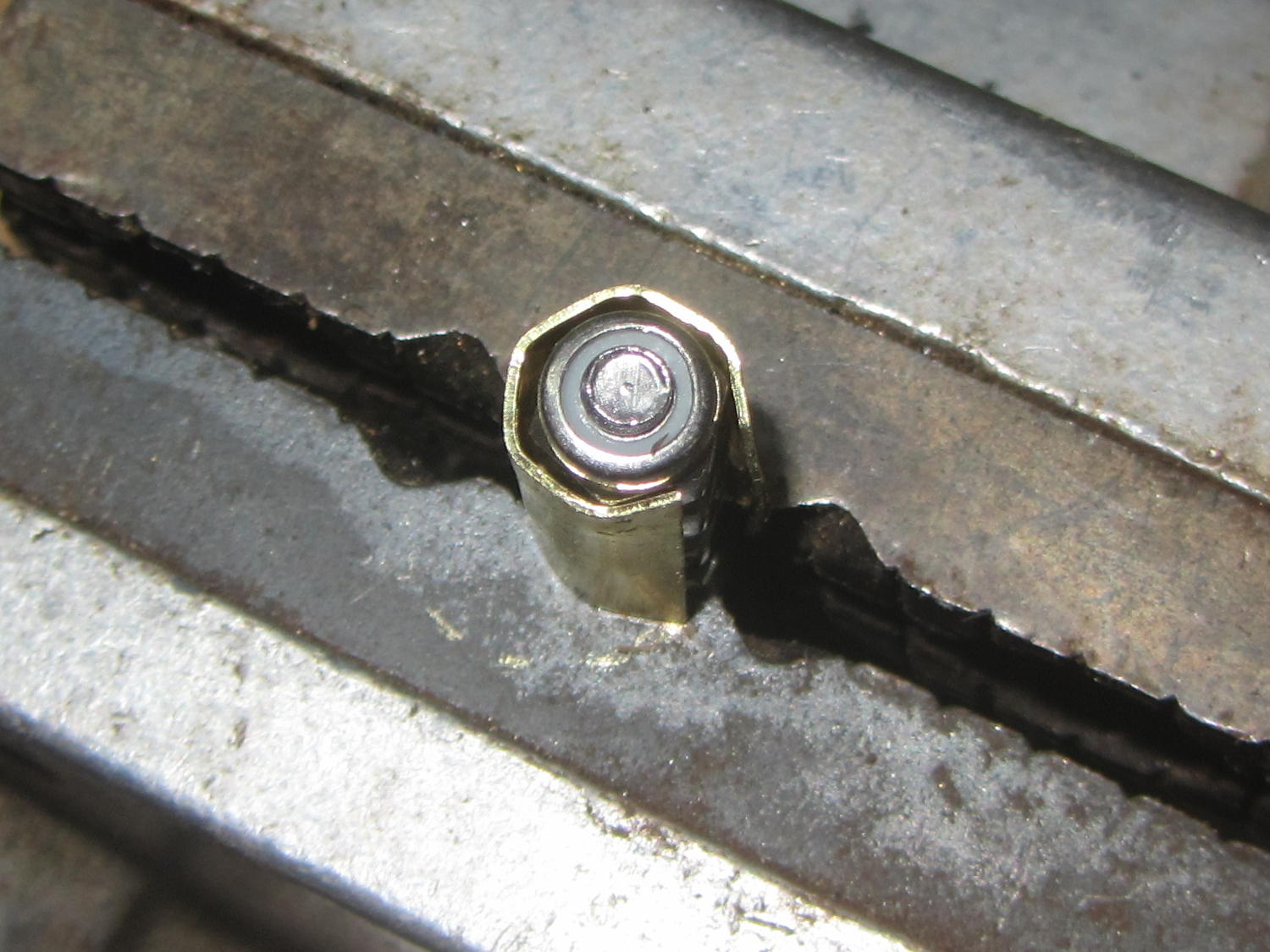
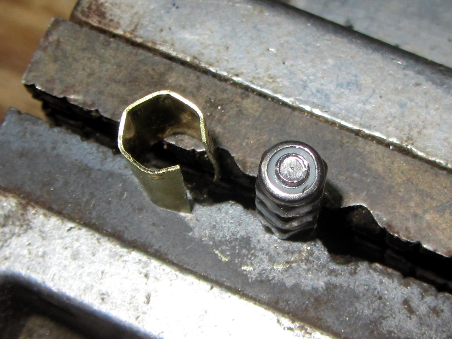
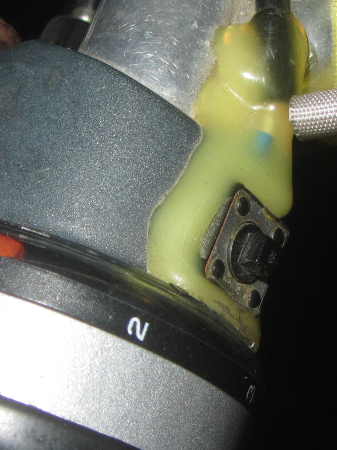
    Twiddle the two setscrews until they’re just barely touching the underside of the carriage (thus ready to hold the strip more-or-less in the proper position), snug the three caps screws, test the fit by sliding the carriage back and forth, and iterate until satisfied. I found the setscrews needed quite a bit more than “barely touching” before the cap screws were tight enough, but your experience may differ.

    Maybe 10 minutes of fiddling changed the overall carriage fit from “barely pushable” to “pretty good”, even with the original (lack of) way finishing in full effect:

    LMS Mini-lathe - carriage flat way - detail
    LMS Mini-lathe – carriage flat way – detail

    My lathe has a loose spot a few inches to the right of the chuck, but it’s now reasonably smooth along the entire length.

    Adjusting the cross-slide and compound gibs will definitely improve their disposition, too.

  • Mini-Lathe: Protecting the Compound Leadscrew

    The first of Ted Hansen’s articles (Home Shop Machinist 31.5 – Sept 2012) showed a very nice cap to keep swarf out of the compound’s leadscrew: neatly shaped brass shimstock, held in place with a pair of screws tapped into the compound base.

    Being a big fan of adhesives and low-effort solutions, I applied stainless steel tape:

    LMS Mini-lathe - compound leadscrew cover
    LMS Mini-lathe – compound leadscrew cover

    Perhaps a 3D printed button might be nicer…

  • Monthly Science: Chrysalid Engineer

    So then this happened:

    Karen - canonical tiger paw graduation picture
    Karen – canonical tiger paw graduation picture

    Yeah, tanker boots and all; not the weirdest thing we saw during RIT’s graduation ceremonies.

    This summer marks her fourth of four co-op semesters with Real Companies Doing Tech Stuff and her final classes end in December; RIT holds one ceremony in the spring and being offset by a semester apparently isn’t all that unusual. She (thinks she) has a job lined up after graduation and doesn’t need her doting father’s help.

    But, hey, should you know someone with a way-cool opportunity (*) for a bright, fresh techie who’s increasingly able to build electronic & mechanical gadgets and make them work, drop me a note and I’ll put the two of you in touch. [grin]

    (*) If that opportunity should involve 3D printed prosthetics with sensors and motors, she will crawl right out of your monitor…

  • Ersatz 5.5 mm Nut Driver

    A tiny 1/4 inch hex driver handle appeared from the far reaches of a drawer, sporting a handle better suited for tweaking the 3 mm adjusting nuts on the bottom of the M2’s platform than applying actual torque to real fasteners. Rather than breaking a set of nut drivers, I made a simple brass shim to soak up the difference between the handle’s 6.5 mm ID hex and the 5.5 mm OD of the nuts:

    Hex driver shim - installed
    Hex driver shim – installed

    That’s 15 mil = 0.40 mm shimstock to leave enough clearance for my crude forming technique.

    Which technique consisted of making a “mandrel” by lining up a trio of Nyloc nuts on a screw, snipping off a suitable shimstock rectangle, and squashing it into shape with parallel-jaw pliers:

    Hex driver shim - forming
    Hex driver shim – forming

    As you’d expect, the shimstock hex came out larger & uglier than the mandrel:

    Hex driver shim - formed
    Hex driver shim – formed

    But that doesn’t matter after it’s tucked inside the driver; it works perfectly.

    Took less time to do than to write up …

  • Micro-Mark Mini Bandsaw

    Unlike their craptastic Mini Miter/Cut-off saw, the Micro-Mark Variable Speed Mini Bandsaw seems like a solid improvement over the corresponding Harbor Freight offering:

    Micro-Mark Bandsaw - mostly ready
    Micro-Mark Bandsaw – mostly ready

    That’s the tank for the water-cooling option atop the housing, with the collection tray underneath. It’s screwed to a big wood plank; I’ll probably bench-mount the thing, but that’s stable enough for now.

    The right-rear mounting screw hides below the dust collection vacuum port:

    Micro-Mark Bandsaw - vacuum fitting
    Micro-Mark Bandsaw – vacuum fitting

    You must remove the metal fitting that’s screwed to the frame in the obvious manner:

    Micro-Mark Bandsaw - right rear screw - installed
    Micro-Mark Bandsaw – right rear screw – installed

    The slowest speed runs a bit faster than I’d like, but I admit to being a sissy.

    The 14 tpi blade cuts wood just fine:

    Micro-Mark Bandsaw - first cut
    Micro-Mark Bandsaw – first cut

    The 24 tpi blades should chop up the smaller chunks I generally work with around here.

    Bonus: the blade guide just barely clears my huge block of machinable wax.


  • Micro-Mark Mini Miter / Cut-off Saw

    I bought a 2 inch Micro-Mark Mini Miter / Cut-off Saw to cut screws & brass tubing, in the hopes that it would be somewhat better than the essentially equivalent Harbor Freight offering. I think that’s true, but it’s a near thing.

    Apparently, the saws all come from the same factory with the same bass-ackwards vise:

    Micro-Mark Cutoff Saw - vise side view
    Micro-Mark Cutoff Saw – vise side view

    The V-groove should be on the fixed jaw, where it would more-or-less precisely align rods / cylinders with the blade. The moveable jaw isn’t dovetailed to the base of the vise, so it ends up wherever it stops and, somehow, they managed to machine the end of the screw shaft off-center from the shaft, so the moveable jaw moves in a small circle as you tighten it.

    A small punch mark locks the jaw to the screw; you can pull the disk on the shaft past the indentation by turning the knob with sufficient enthusiasm:

    Micro-Mark Cutoff Saw - clamp jaw detail
    Micro-Mark Cutoff Saw – clamp jaw detail

    The hole in the vise, just under the disk, lets somebody whack the jaw with a punch.

    Some machining or an entirely new vise setup lies in the future of this thing.

    I mounted it on a scrap of countertop by transfer-punching the base holes, only to discover that the punch didn’t leave a mark for one hole, even though a dent was clearly visible at the bottom of the hole with the saw on the countertop.

    A bit of headscratching later:

    Micro-Mark Cutoff Saw - unfinished casting hole
    Micro-Mark Cutoff Saw – unfinished casting hole

    Apparently the core for that hole in the injection mold didn’t seat quite right. The layer was thin enough to drill out easily.

    The blade is identical with the Harbor Freight blades I’m using on the Sherline, right down to the printed legend declaring it fits saws with non-Micro-Mark part numbers:

    2 inch blades - Micro-Mark vs Harbor Freight
    2 inch blades – Micro-Mark vs Harbor Freight

    Granted, the Micro-Mark blade on the left has nicer printing, but MM blades run $15 each and HF offers a three-pack for ten bucks. Note the carefully positioned thumb in the Micro-Mark picture.

    Beware of cheap imitations!” says Micro-Mark.

  • APRS/GPS + Voice Interface: Improved PTT Button Cap

    Long ago, Mary picked out a PTT switch with a raised, square post that provided a distinct shape and positive tactile feedback:

    PTT Button - bare post
    PTT Button – bare post

    Time passes, she dinged her thumb in the garden, and asked for a more rounded button. I have some switches with rounded caps, but replacing the existing switch looked a lot like work, sooooo:

    PTT Button Cap - Slic3r preview
    PTT Button Cap – Slic3r preview

    As with all small objects, building them four at a time gives the plastic in each one time to cool before slapping the next layer on top:

    PTT Button - on platform
    PTT Button – on platform

    The hole in the cap is 0.2 mm oversize, which results in a snug press fit on the small ridges barely visible around the post in the first image:

    PTT Button - rounded cap
    PTT Button – rounded cap

    Rather than compute the chord covering the surface, I just resized a sphere to twice the desired dome height (picked as 6 threads, just for convenience) and plunked it atop a cylinder. Remember to expand the sphere diameter by 1/cos(180/sides) to make it match the cylinder and force both to have the same number of sides.

    If it falls off, I have three backups.

    The OpenSCAD source code as a GitHub Gist:

    // PTT Button cap
    // Ed Nisley KE4ZNU – June 2016
    //- Extrusion parameters – must match reality!
    ThreadThick = 0.20;
    ThreadWidth = 0.40;
    Protrusion = 0.1;
    HoleWindage = 0.2;
    //——
    // Dimensions
    Post = [3.8,3.8,3.0];
    OD = 0;
    HEIGHT = 1;
    DOMEHEIGHT = 2;
    Button = [12,0+Post[2],6*ThreadThick];
    NumSides = 8*4;
    //———————-
    //- Build it
    difference() {
    union() {
    translate([0,0,Button[HEIGHT]])
    resize([0,0,2*Button[DOMEHEIGHT]])
    sphere(d=Button[OD]/cos(180/NumSides),$fn=NumSides);
    cylinder(d=Button[OD],h=Button[HEIGHT],$fn=NumSides);
    }
    translate([0,0,Post[2]/2 – Protrusion])
    cube(Post + [HoleWindage,HoleWindage,Protrusion],center=true);
    }