Ed Nisley's Blog: Shop notes, electronics, firmware, machinery, 3D printing, laser cuttery, and curiosities. Contents: 100% human thinking, 0% AI slop.
Tag: Improvements
Making the world a better place, one piece at a time
It’s certainly the shapeliest hydrant I’ve ever seen.
Of course, you need a special tool to remove the main cap, after which some internal lockwork releases the side caps, after which you can spin the valve stem recessed under the top cover. One hopes all those little bits continue sliding and releasing after a few decades, but … the status quo apparently isn’t all that good, either.
Baofeng UV-5 radios can (mostly) eliminate the loud hiss heard at the end of a transmission before the squelch kicks in after the received carrier drops: Menu → 34 STE → ON. A detailed description of the option suggests it’s a 55 Hz subaudible tone sent for 250 milliseconds after the sender releases the PTT and before the transmitter stops sending, with the receiver muting its audio during the tone. Obviously, this requires a Baofend radio at each end of the conversation, which applies to our bikes.
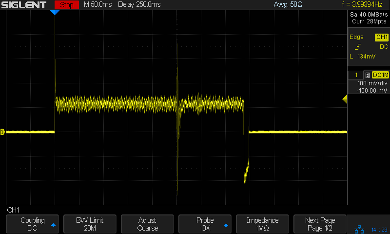
Saying “laaaa” while kerchunking (into a smaller dummy load than the hulk) with STE OFF:
Baofeng – STE OFF – laaaa
Compared to the received audio, the squelch tail hiss is really really loud.
Then with STE ON:
Baofeng – STE ON – laaaa
You can see the STE tone reception start about 250 ms before the audio cuts off, although it’s not at all clear the audio is muted on either end. In any event, there’s no squelch tail worth mentioning, even if there’s an audible tick when the STE tone starts.
Saying nothing with STE ON:
Baofeng – STE ON – silent
It’s unlikely the audio output would include the subaudible tone, but you might convince yourself something happens in the 250 ms between the STE blip near midscreen and the final pop (now clipped) as the audio drops.
Perhaps because we’re using better quality earbuds, the Baofeng UV-5 radios on our bikes produce extremely loud audio, even with the volume knob just above its power-on click. Reducing the volume requires a series resistor downstream of the diodes clipping the pops:
Because we have different earbuds and different hearing, my radio has a 140 Ω resistor and Mary’s has a 430 Ω resistor. Getting the right value requires a few iterations of on-road testing, but it’s not particularly critical; the volume knob should end up roughly in the middle of its range.
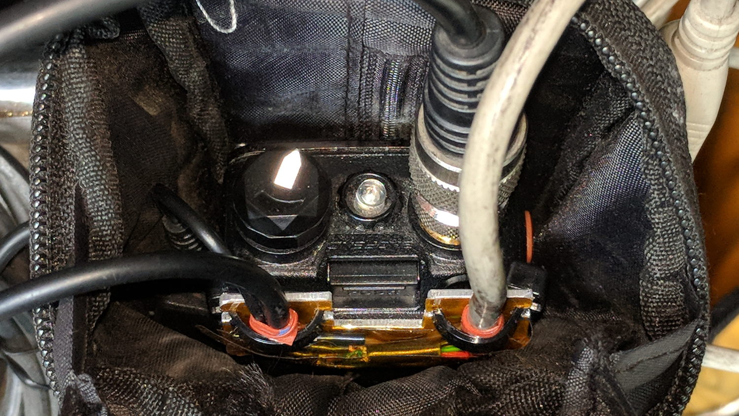
For now, all the “circuitry” lives among layers of Kapton tape:
Baofeng headset wire plate – detail
Speaking of volume knobs, Baofeng radios have large flat-top cylindrical knobs (unlike Wouxun’s fluted knobs), so I added a pointed snippet of reflective tape to make the position visible:
Baofeng volume knob – reflective pointer
The flash lights it up, but there’s enough backlighting behind your (well, my) head to make it easily visible under normal conditions. Once you figure out the proper volume, it’s easy to set the pointer in that direction before every ride.
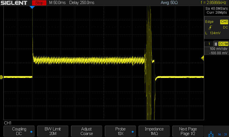
Our first ride with the Baofeng UV-5 radios subjected us to loud pops around each transmission. Back on the bench, this is the signal applied to the earbud during a no-audio simplex kerchunk:
Baofeng – squelch pops
The small noise burst to the right of the center, just before the downward pulse, happens after the carrier drops and before the squelch closes; it’s familiar to all HT users.
The huge pulses, upward at the start and downward at the end, cause the pops. They’re nearly 3 V tall, compared with the 300-ish mV squelch noise, and absolutely deafening through an earbud jammed in my ear. Mary refused to listen, so we finished the first ride in companionable silence.
I think the radio switches the audio amp power supply on and off to reduce battery drain. It’s obviously a single-supply design, so we’re looking at a hefty DC blocking capacitor charging and discharging through the earbud resistance. I suppose that’s to be expected in a $25 radio.
The obvious solution: clamp the audio signal to something reasonable, perhaps with a pair of nose-to-tail Schottky diodes across the earbud. Rather than using axial diodes, along the lines of the 1N5819 diodes in the WWVB preamp, I used a BAT54S dual SMD diode as a tiny clamp:
BAT54S dual-Shottky diode – SMD package
No pix of the final result, but it’s basically two wires soldered alongside the SMD package, surrounded by a snippet of heatstink tubing to stabilize the wires and protect the SMD leads. It might actually survive for a while, even without the obligatory epoxy blob.
The BAT54S clamps the pops to 200-ish mV, as you’d expect:
Baofeng – squelch pops – clamped – 500mV-div
That’s a kerchunk at twice the vertical scale. The very thin spike at the start of each pop isn’t audible, as nearly as we can tell, and I’ve cranked up the audio gain to make the squelch noise more prominent. Your ears will determine your knob setting.
With the audio amp applying 3 V to the diodes at the start of each pop, you’re looking at an absurdly high pulse current. I’m sure the radio exceeds the BAT54 datasheet’s 600 mA surge current limit by a considerable margin, but I’m hoping the short duration compensates for some serious silicon abuse.
Tamping those pops down made the radios listenable.
I’ve often observed that Baofeng radios are the worst HTs you’d be willing to use.
My venerable amateur radio HT APRS-voice interfaces have recently begun failing and, given poor APRS coverage in Poughkeepsie due to having two iGates shut down (due to the aging radio geek population), I decided it’s time to simplify the radio interface. Given that HTs are designed to run with an external electret mic and earbud, the “interface” becomes basically some wires between the radio’s jacks, a repurposed USB plug on the bike helmet, and the PTT switch on the handlebar.
I expected to add a resistive attenuator to the earbud, but it wasn’t clear whether the mic would need an amplifier similar to the one in the APRS interface, so I decided to start as simply as possible.
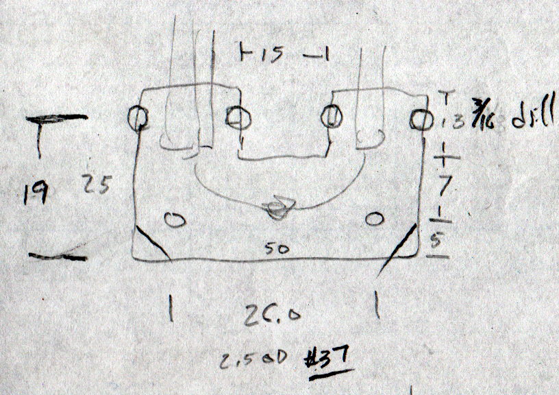
The general idea is to anchor all the cables to a plate on the back of the radio, interconnect as needed, then “protect” everything with tape. The pocket clip has M2.5 screws on 26 mm (not 25.4, honest) centers, so that’s how it started:
Baofeng headset wire plate – dimensions
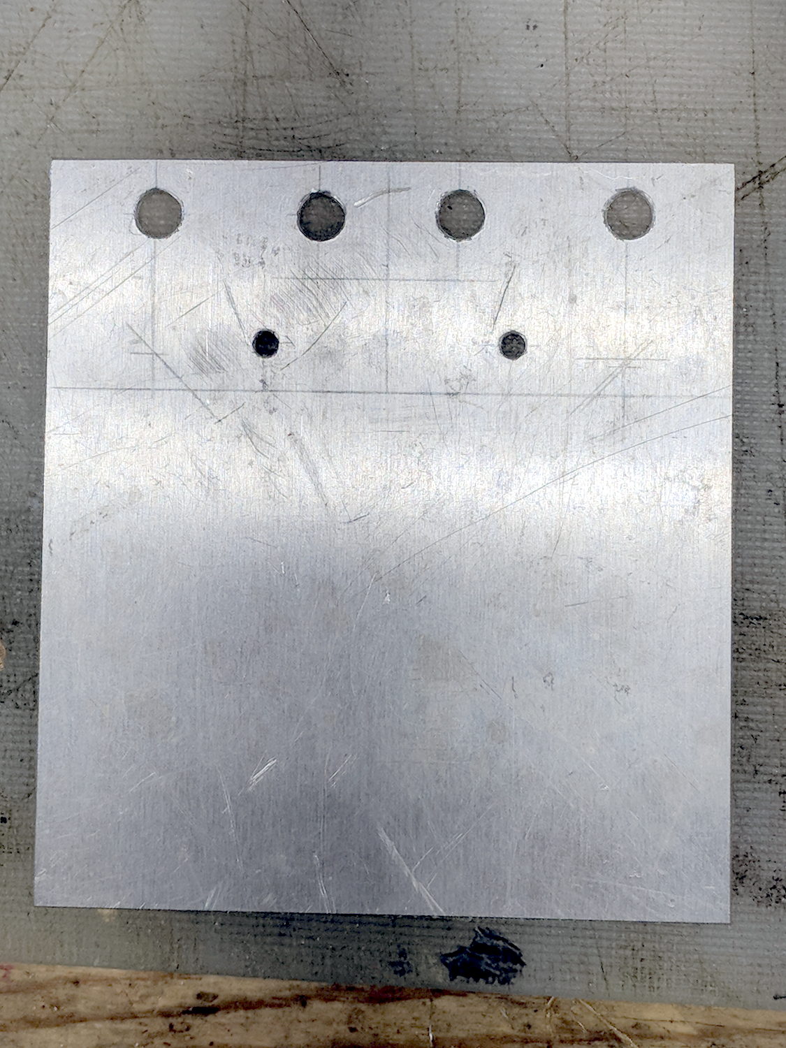
The four holes beside the tabs will serve as starting points for rectangular notches holding cable ties lashing the wires to the plate:
Baofeng headset wire plate – drilled
Like this:
Baofeng headset wire plate – sawed
That’s hot and nasty, straight from the bandsaw.
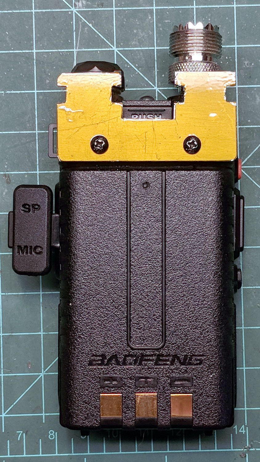
After some edge cleanup, add obligatory Kapton tape to insulate stray wires from the aluminum:
Baofeng headset wire plate – installed
The alert reader will note beveled corners on one plate and square corners on the other; think “continuous product improvement”.
The big rectangular gap in the middle of the plate provides (barely enough) finger clearance to push the battery release latch.
Now, to wire it up …
The dimensions of the recess surrounding the jacks on the Baofeng UV-5, just to have them around:
Baofeng headset jack socket – dimension doodle
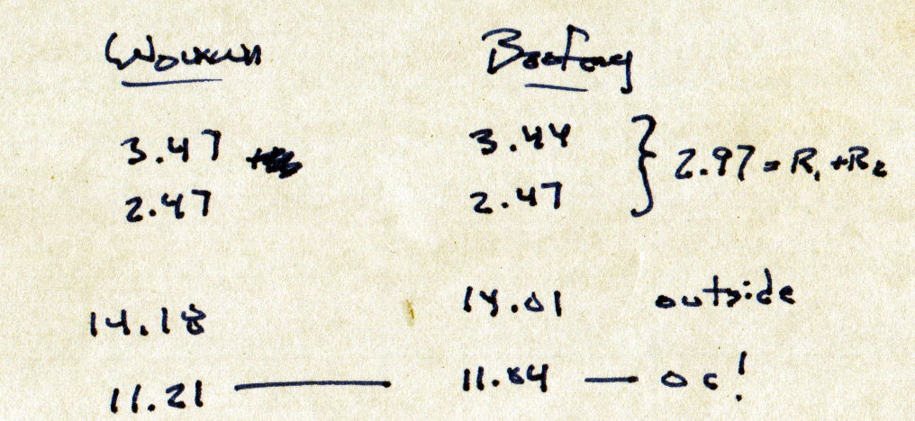
Which came from measurements of both the Wouxun and Baofeng radios:
Baofeng Wouxun headset jack sockets – measurements