Ed Nisley's Blog: Shop notes, electronics, firmware, machinery, 3D printing, laser cuttery, and curiosities. Contents: 100% human thinking, 0% AI slop.
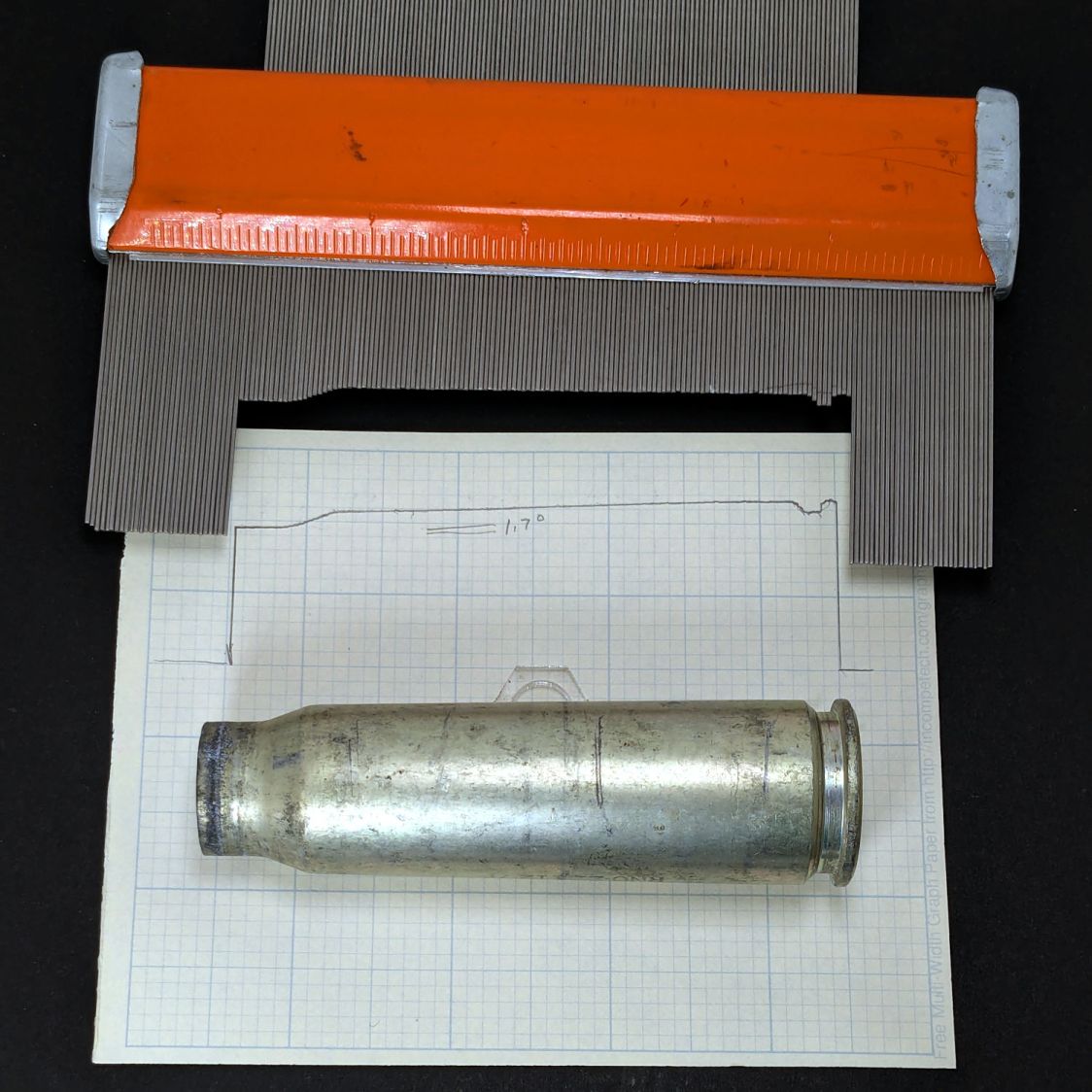
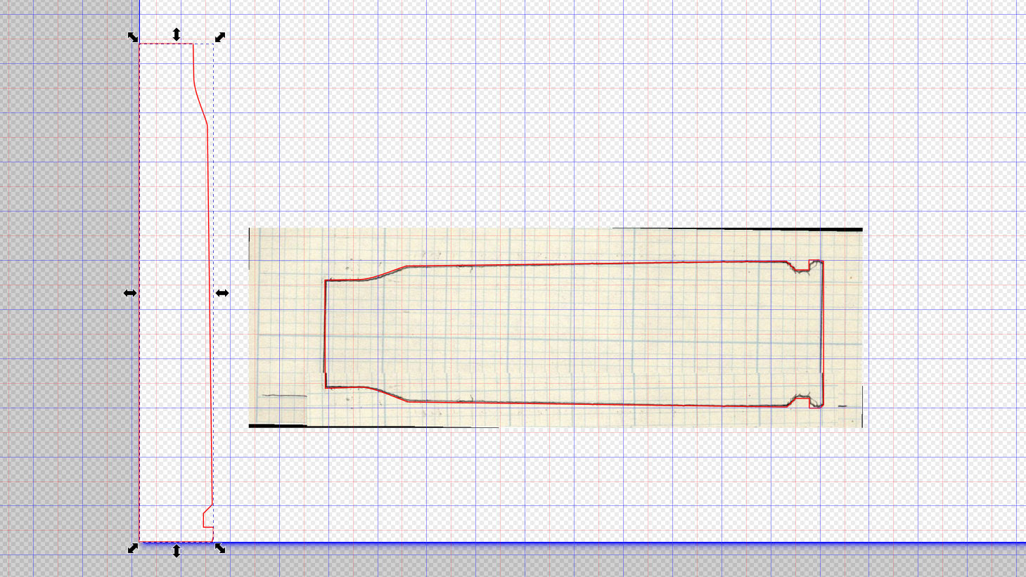
Scan the sketch, import into Inkscape, rotate the image to correct the case taper angle vs. the page, lay lines & curves around the perimeter, align half of it at the page origin to work with OpenSCAD, export as SVG:
Cartridge – 20x102mm outline – Inkscape layout
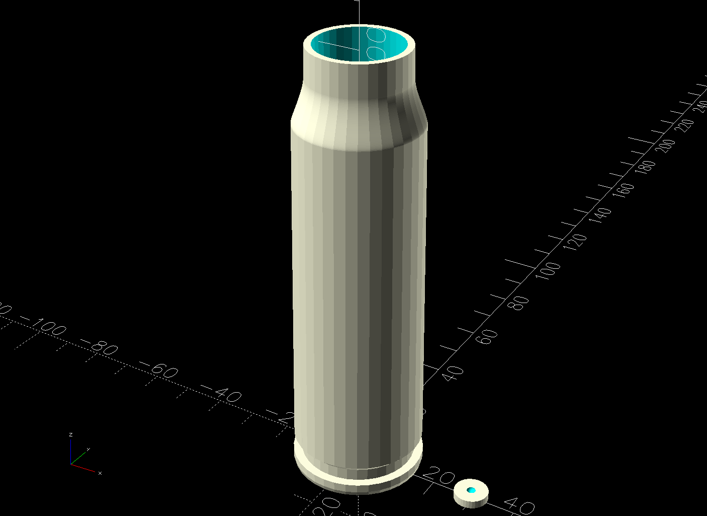
Import into OpenSCAD, let rotate_extrude do the heavy lifting, and remove some pieces:
Cartridge Case – build view solid model
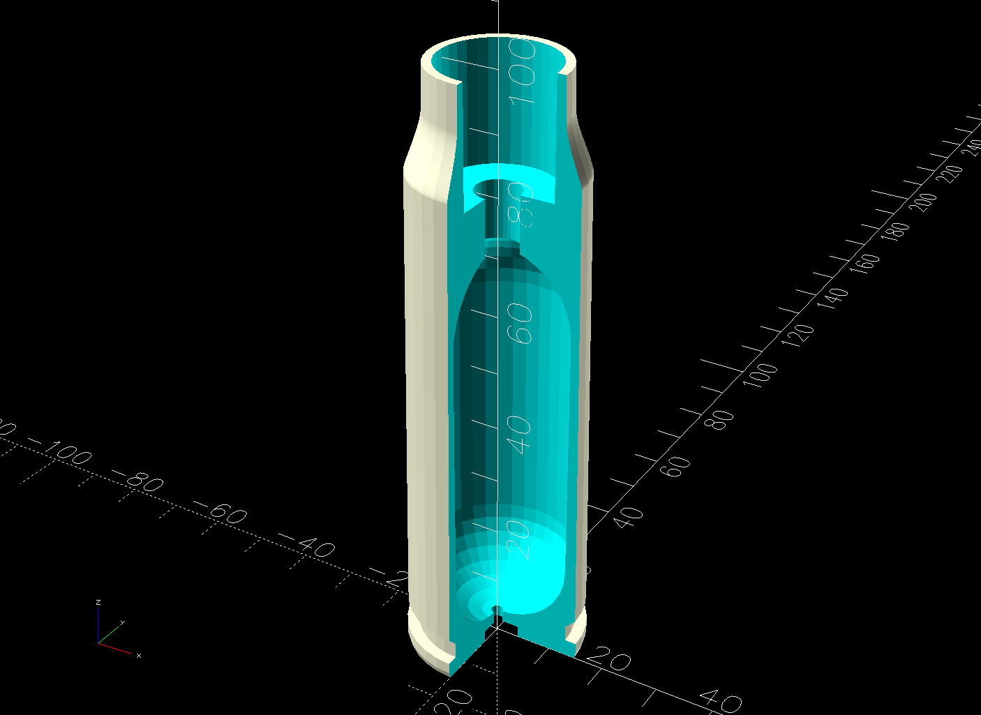
The little disk represents a fired primer you’d print separately in a different color and glue into the pocket shown in this cutaway view:
Cartridge Case – cutaway solid model
The interior void could hold sand for additional heft, as the whole thing is obviously nose-heavy; that’s certainly in the nature of fine tuning. Obviously, we are not dealing with anything that could go bang.
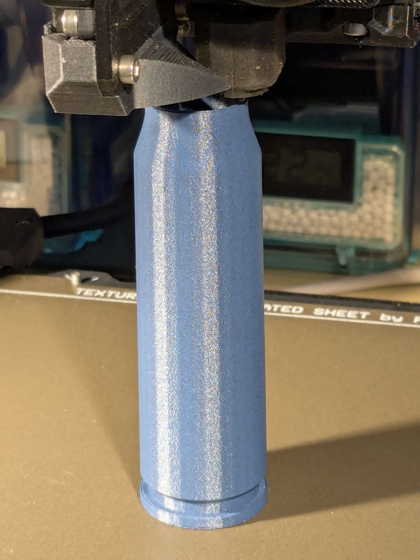
It builds just like you’d expect:
20x102mm cartridge – printing
Dab some adhesive on the capsule tip, ditto for the primer, stick them in place, and it’s all good.
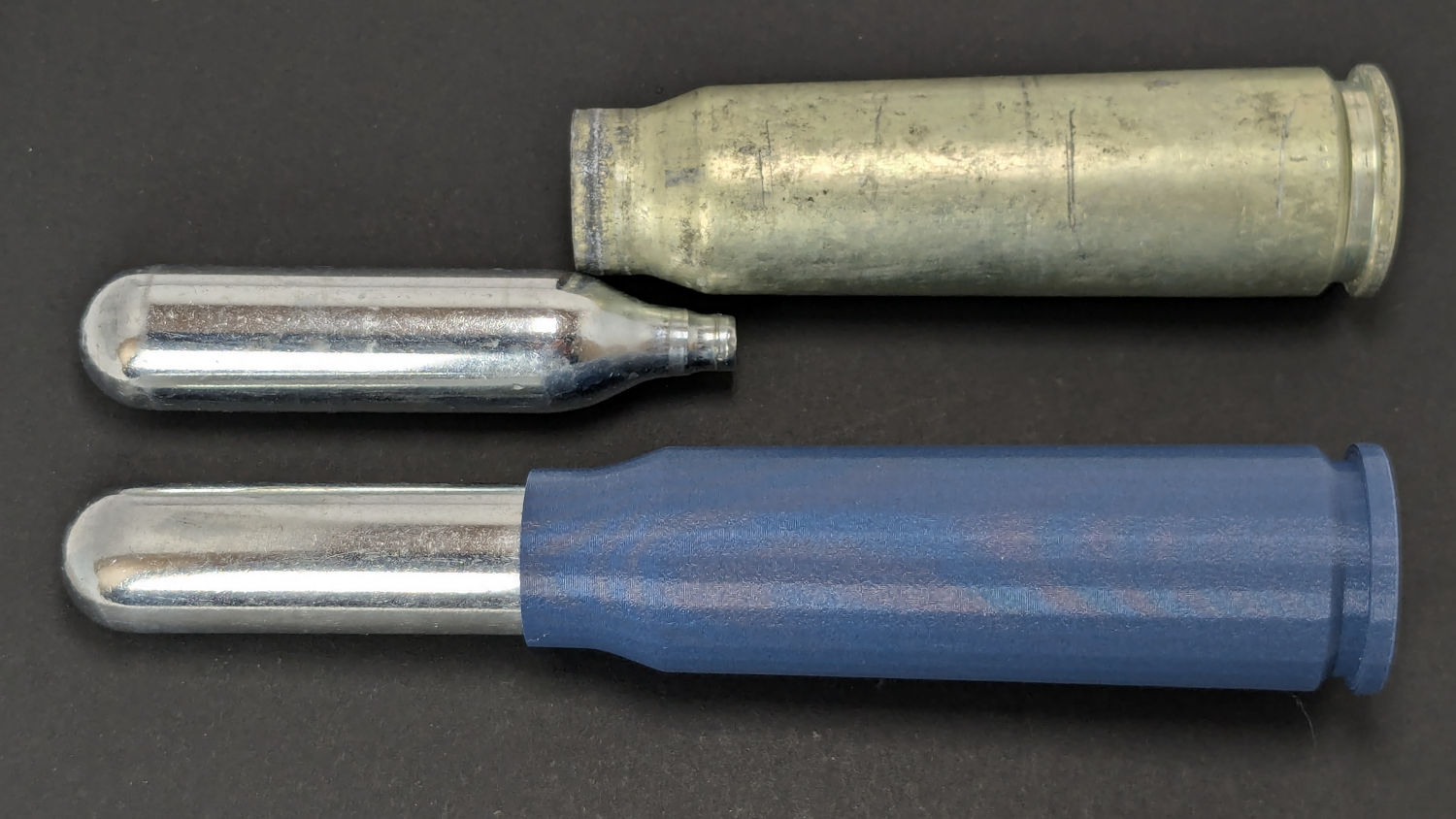
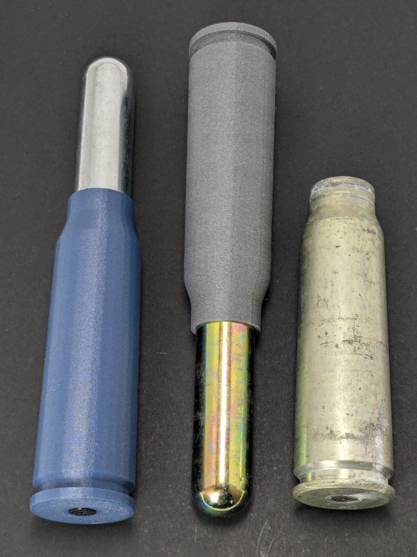
I like the gray PETG-CF version:
20x102mm cartridges – blue gray PETG-CF
Maybe not such a good idea in this day & age. Print responsibly, as they say.
Update
Print a sabot to fit a CO₂ capsule into a genuine steel cartridge.
This file contains hidden or bidirectional Unicode text that may be interpreted or compiled differently than what appears below. To review, open the file in an editor that reveals hidden Unicode characters.
Learn more about bidirectional Unicode characters
We explored the interior for several hours, all the way to the lower Turret 2 barbette:
USS Massachusetts BB-59 – Turret 2 Lower Barbette 16 inch Shell Storage
Each 16 inch projectile weighs 2700 pounds, with 800 shells distributed around three turrets. Looking at the drawings doesn’t make up for seeing the machinery.
The Massachusetts did shore bombardment during the Solomon Island campaign, where my father was assigned to guard a forward observer targeting Japanese redoubts and caves. He said the first rounds went over the far horizon, the second group landed short in the valley, and, from then on, the observer called out coordinates, walked the impact points down the valley, and wiped out each target in succession. BB-59 may not have been on the other end of those trajectories, but he said the Navy saved them plenty of trouble and inconvenience …
For reasons that aren’t relevant here, I had to reinforce some old basement stairs. Rather than drilling holes, sinking anchors, and installing screws, I just nailed painted 2×4 strips to the foundation using this Craftsman 1231.3817 Power Hammer, which is not available in a Sears / Kmart near you:
Sears Craftsman Power Hammer
It’s a handheld gun that drives two inches of hardened steel nail into solid concrete by firing what looks like an overstuffed 0.22 Short blank cartridge: load a nail, fit a cartridge, press the muzzle firmly against the target, and whack the butt end with a hammer.
Worked like a champ. Scary as you’d imagine.
If the nail stands proud of the surface, you can hit it again with a low(er) power load to drive it the rest of the way. Sometimes that sinks it below the surface, leaving a cylindrical pit. In the situations where I use this thing, nobody will ever notice.
It’s similar to the Remington Model 476 Powder Actuated Fastening Tool (manual), which you can get from Amazon and surely other vendors; fancier versions also exist. Equally surely, they’re illegal in some jurisdictions.
I have reason to use it every few decades, which is entirely enough for me…
Wear goggles, earplugs, gloves, and don’t get stupid.
According to Wikipedia, the M110A2 8 inch / 203 mm Self-Propelled Howitzer became obsolete when improvements in smaller guns matched its range and firepower. The double-vent muzzle brake is diagnostic for the A2 model.
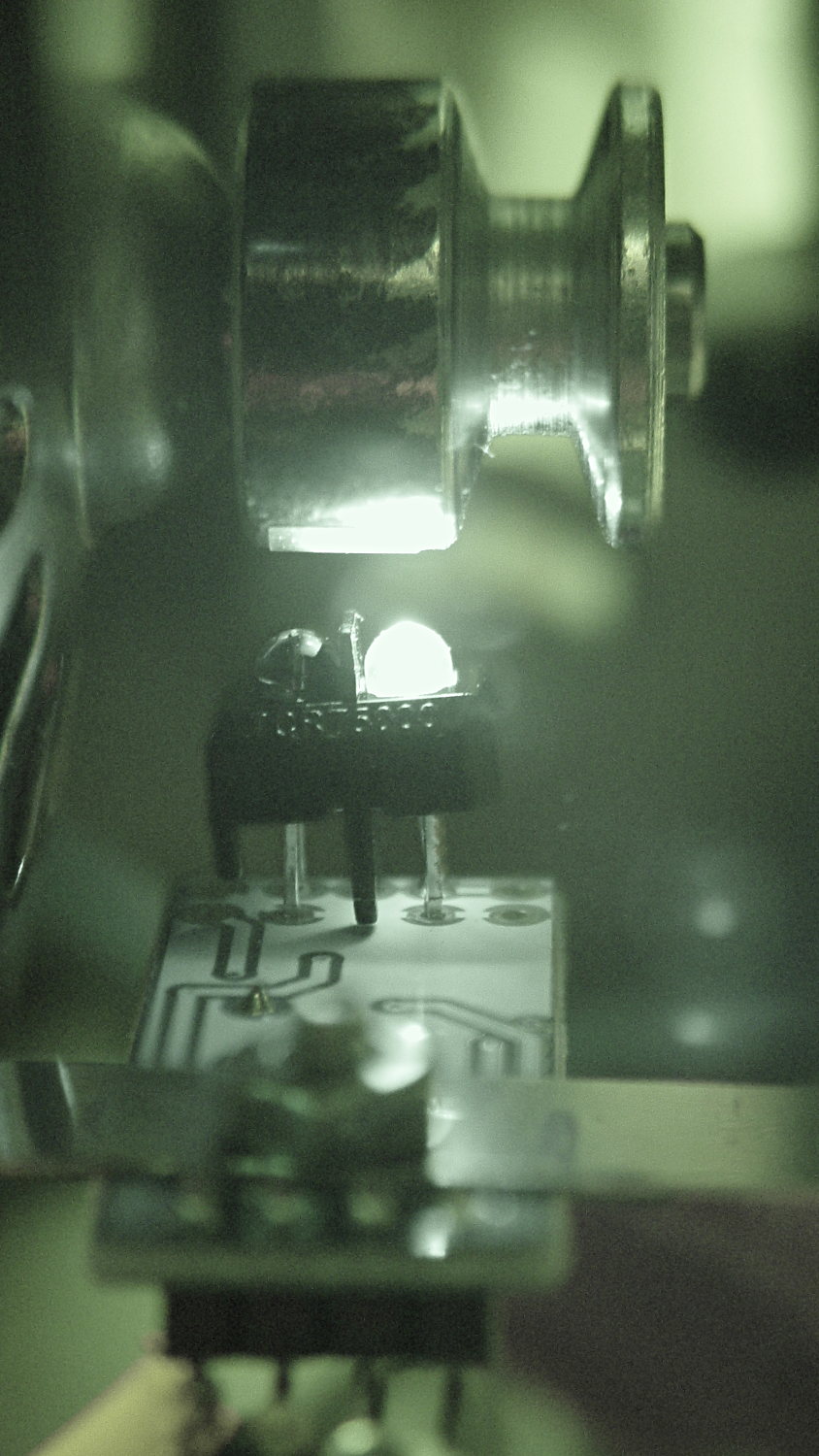
A quick-and-dirty bracket (made from a leftover strip in the pile of chassis clips) affixed an IR reflective sensor (based on the ubiquitous TCRT5000 module) to the sewing machine motor:
TCRT5000 sensor on motor
That’s scribbling black Sharpie around the retroreflective tape for the laser tachometer, which worked just about as poorly as you’d expect. Retroreflective tape, by definition, reflects the light directly back at the LED, but in this case you want it bounced to the photosensor.
An IR view shows the geometry and highlights the LED:
TCRT5000 sensor – IR view
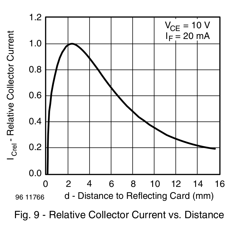
The TCRT5000 datasheet suggests that the peak operating distance is 2.5 mm, roughly attained by tinkering with the bracket. The datasheet graph shows that anything between 1 and 5 mm should be just fine:
IR Reflective Sensor module – TCRT5000 – response vs distance
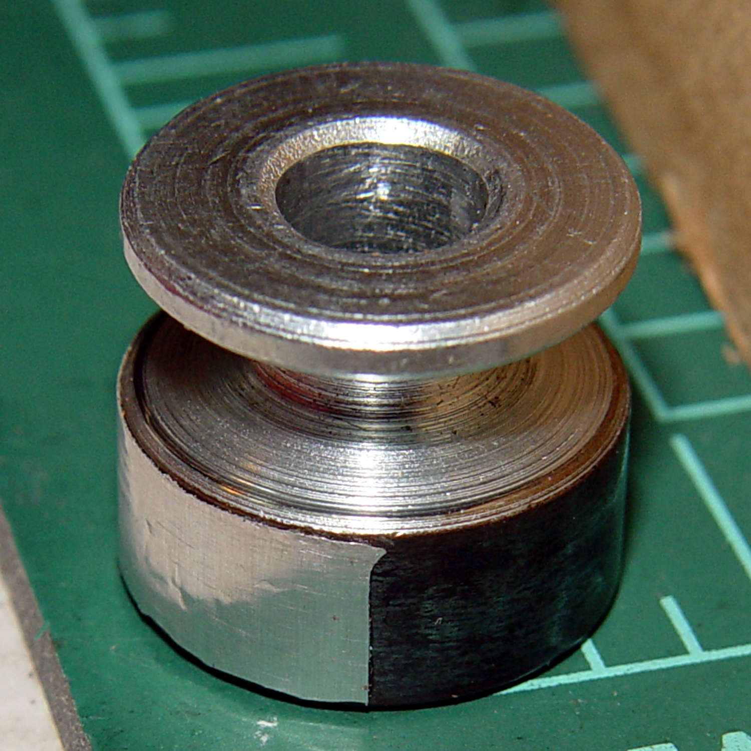
Apply stainless steel tape around half the circumference
Burnish flat
Which looks pretty good:
Kenmore 158 motor pulley – black-silver
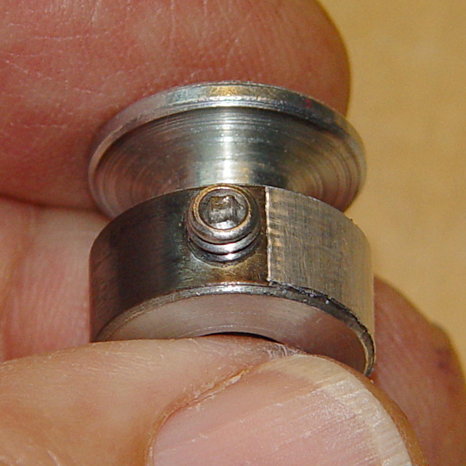
The stainless tape butts up against the setscrew:
Kenmore 158 motor pulley – black-silver at setscrew
Adjusting the sensitivity midway between the point where the output is low (OFF) over the black and high (ON) over the tape seems reasonable.
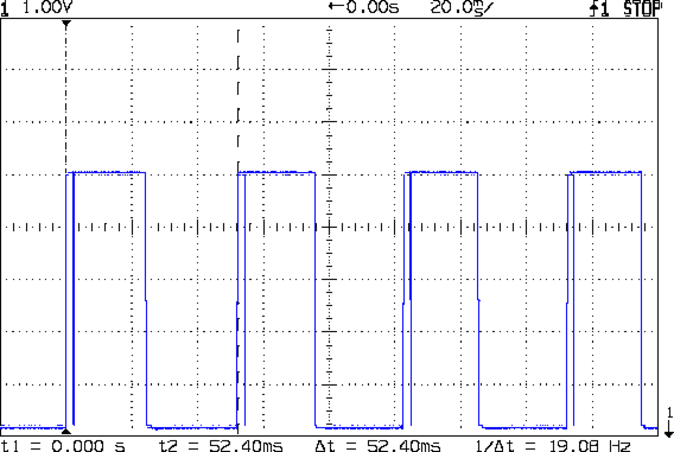
Running at the slowest possible speed produces this pulse train:
Motor sense – min speed
The motor at 19 rev/s = 1140 RPM corresponds to about 2 rev/s of the sewing machine shaft= 2 stitch/s. Slower than, that, the pedal won’t go in simple open-loop mode.
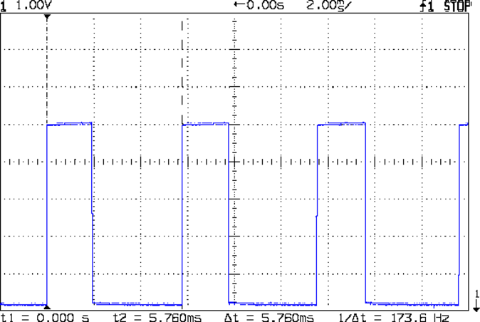
The setscrew causes those “glitches” on the rising edge. They look like this at a faster sweep:
Motor sense – min speed – setscrew
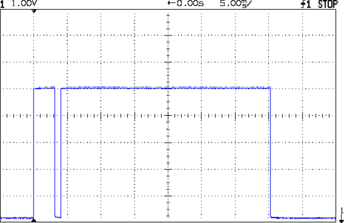
At maximum speed, the setscrew doesn’t show up:
Motor sense – max speed
The motor at 174 rev/s = 10440 RPM would do 1000 stitch/s, but that’s just crazy talk: it runs at that speed with the handwheel clutch disengaged and the motor driving only the bobbin winder. I was holding the machine down with the shaft engaged and all the gimcrackery flailing around during that shot.
The sensor board may have an internal glitch filter, but it’s hard to say: the eBay description has broken links to the circuit documentation.
I could grind the setscrew flush with the pulley OD and cover it with tape, but that seems unreasonable. Fixing the glitch in firmware shouldn’t be too difficult: ignore a rising edge that occurs less than, say, 1/4 of the previous period following the previous edge.
Perhaps buffing half the pulley’s circumference to a reasonable shine (minus the bluing) would eliminate the need for the stainless steel tape.
Iterating the bluing operation / scrubbing with steel wool should produce a darker black, although two passes yields a nice flat black.
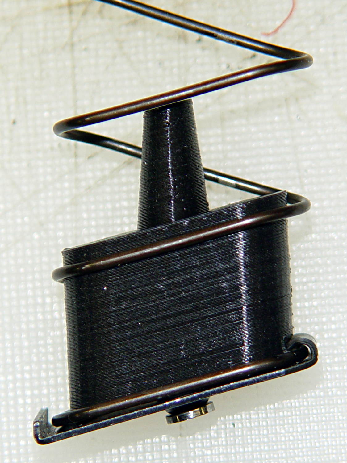
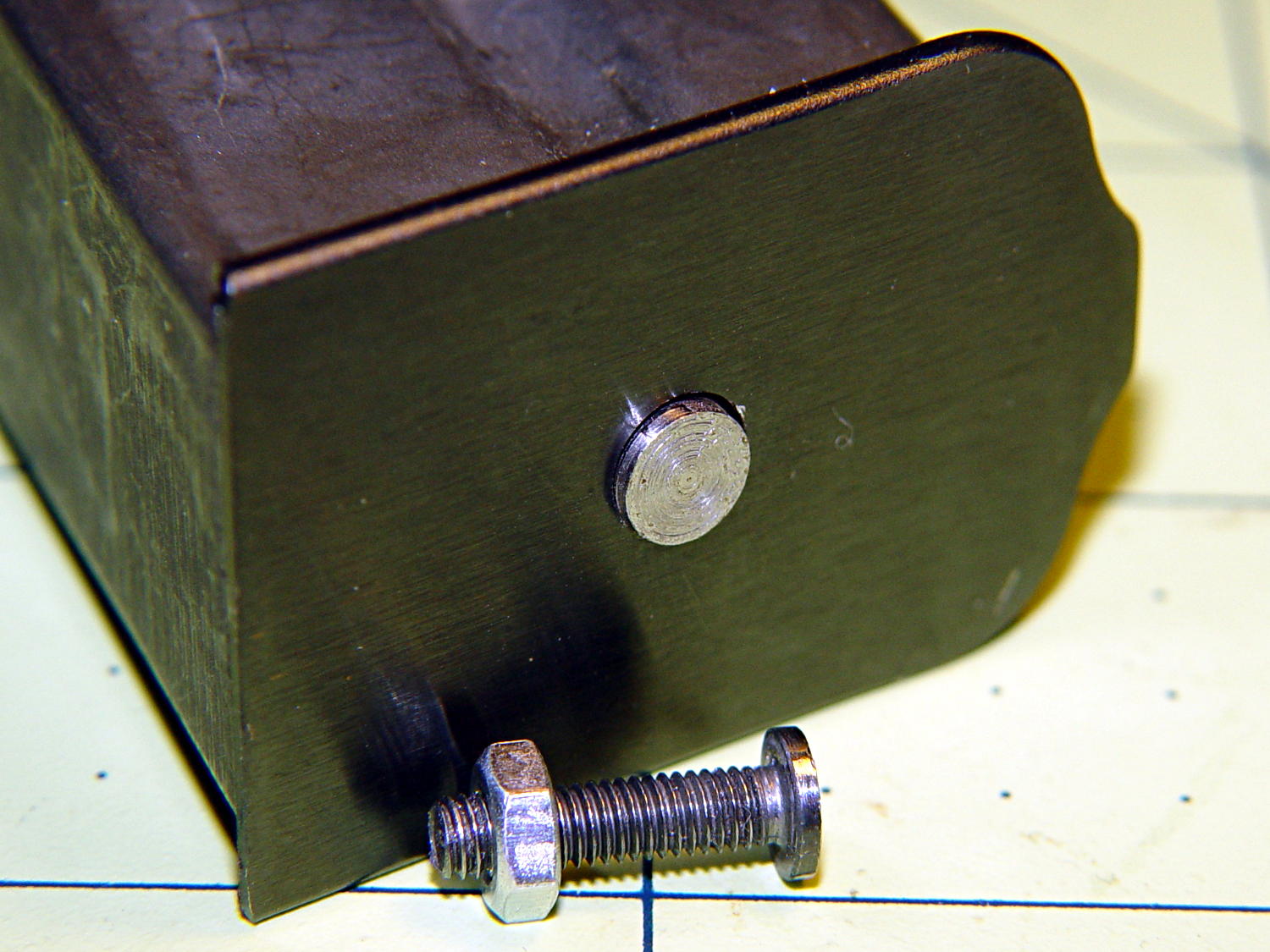
It started as a normal M3x0.5 socket-head cap, but I reduced the diameter and turned off the socket to fit the existing hole in the exterior floor plate:
BHP floor plate screw – disk head
The head was just barely too large for the largest of my pin vises. Drat!
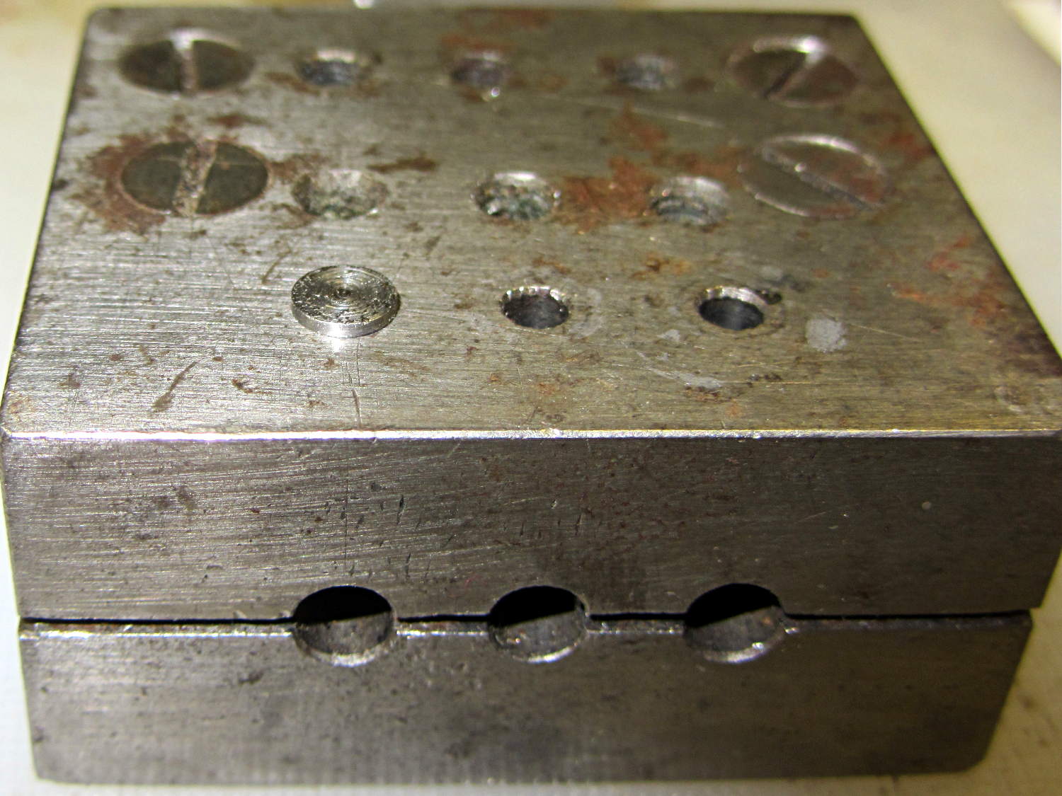
The easiest way (for me, anyhow) to install that screw into the epoxy-loaded block started by dropping it into what seems to be a shim-punching tool:
Base screw in alignment block
It’s in the left hole of the top front row: talk about protective coloration, eh?
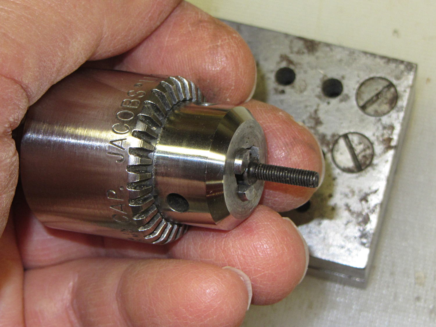
Then capture it in one of the Sherline’s drill chucks:
Base screw in Jacobs chuck
Which makes it trivially easy to turn right into the nut brazed to the floor plate and the epoxy inside the block. When the epoxy cures, the screw, nut, floor plate, spring, and block become one solid unit.
That punch block came with the lathe tooling, made for some special purpose long lost in history. It comes in handy all the time for other jobs, though, so I think it’s still happy.
(*) The pictures are staged recreations; I was cleaning off the bench and unearthed the spare screws.
Although commenting out an undesired variable isn’t fashionable, OpenSCAD doesn’t have a practical mechanism to set specific values based on a control variable:
if-then-else deals with geometric objects
(boolean)?when_true:when_false (the ternary operator) doesn’t scale well
You could, of course, depend on OpenSCAD’s behavior of using the last (in syntactic order) instance of a “variable”, but IMHO that’s like depending on semantic whitespace.
In any event, the rest of the block builds itself around those three values by recomputing all of its dimensions.
The Browning OEM block looks like this:
Browning Hi-Power Magazine Block – solid model – BHP OEM
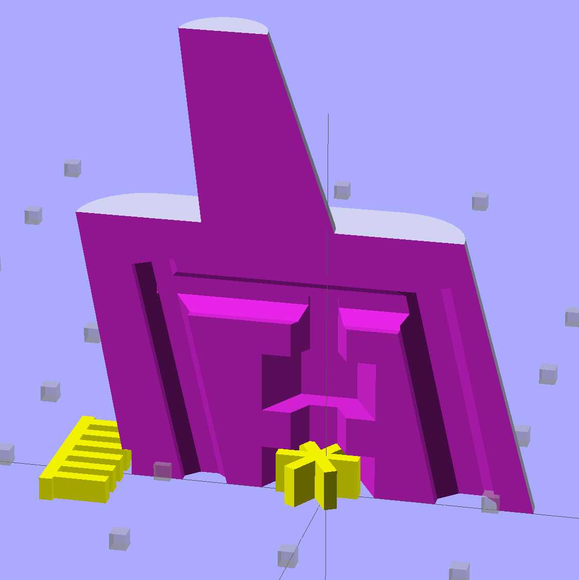
The Generic floorplate has a much larger spring retaining crimp, so the block has far more overhang:
Browning Hi-Power Magazine Block – solid model – Generic 1
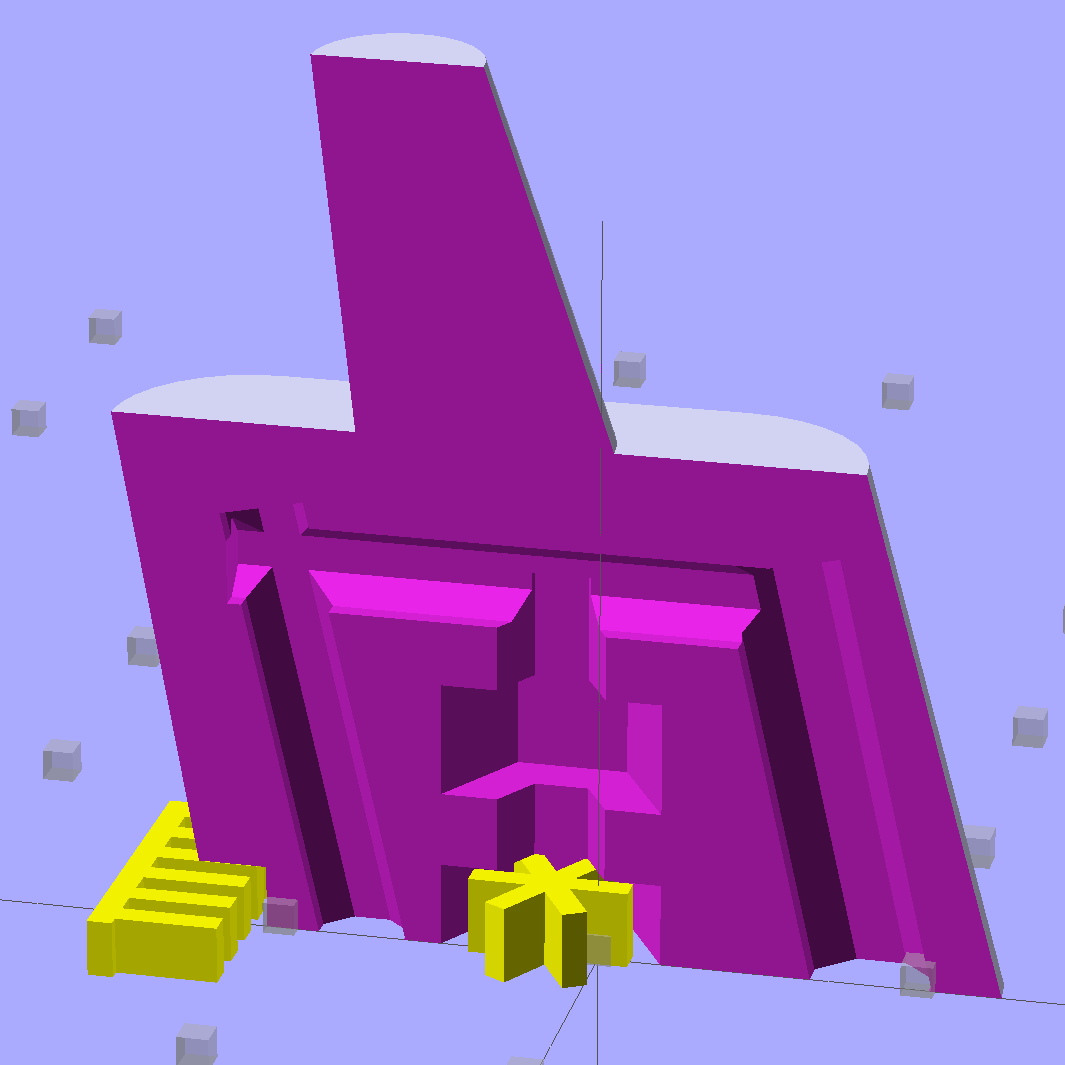
As before, the yellow widgets are built-in support structures separated from the main object by one thread thickness and width. That seems to maintain good vertical tolerance and allow easy removal; the structures snap free with minimal force. A closeup look shows the gaps:
Browning Hi-Power Magazine Block – solid model – Generic 1 – support detail
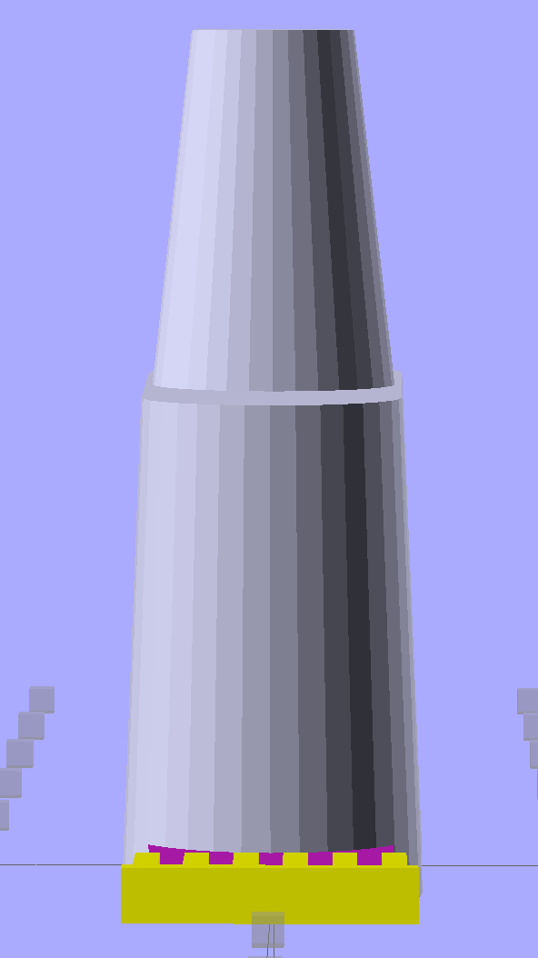
The main shape now has a 2 mm taper to ease the magazine spring past the upper edge of the block. The horn remains slightly inset from the side walls to ensure that the whole thing remains manifold:
Browning Hi-Power Magazine Block – solid model – Generic 1 – whole end
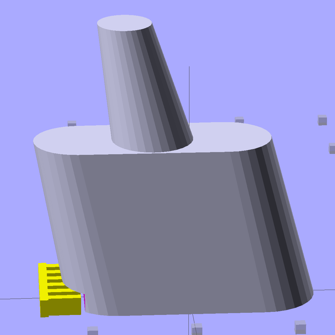
The whole object looks about the same, though:
Browning Hi-Power Magazine Block – solid model – Generic 1 – whole side
The shape descends from the geometry I used for the stainless steel block, with the additional internal channel (on the right in the models) to be filled with steel-loaded epoxy during assembly. That should make the whole block sufficiently robust that you must destroy the floorplate and distort the spring to get it out; wrecking the magazine’s innards should count as not “readily” modifiable.
Some destructive testing seems to be in order…
The OpenSCAD source code:
// Browning Hi-Power Magazine Plug
// Ed Nisley KE4ZNU December 2013
// February 2014 - easier customization for different magazine measurements
Layout = "Whole"; // Whole Show Split
// Whole = upright for steel or plastic
// Show = section view for demo, not for building
// Split = laid flat for plastic show-n-tell assembly
AlignPins = true && (Layout == "Split"); // pins only for split show-n-tell
Support = true && (Layout != "Split"); // no support for split, optional otherwise
// Define magazine measurements
//BlockData =  [-0.5, 1.5, 11.5];	// Browning OEM
BlockData = [-1.5, 2.0, 9.0];		// Generic 1

SCREWOFFSET = 0;
CRIMPHEIGHT = 1;
CRIMPDISTANCE = 2;
//- Extrusion parameters must match reality!
// Print with 2 shells and 3 solid layers
ThreadThick = 0.20;
ThreadWidth = 0.40;
HoleWindage = 0.2;
Protrusion = 0.1; // make holes end cleanly
function IntegerMultiple(Size,Unit) = Unit * ceil(Size / Unit);
//----------------------
// Dimensions
Angle = 12.5; // from vertical
SpringID = 10.3; // magazine spring curvature (measure with drill shank)
SpringRadius = SpringID / 2;
Taper = 2.0; // total taper toward top
Length = 24.5; // front-to-back perpendicular to magazine shaft
Height = 17.0; // bottom-to-top, parallel to magazine shaft
RectLength = Length - SpringID; // block length between end radii
HornBaseOD = 8.0; // fits between follower pegs to prevent shortening
HornTipOD = 5.0;
HornAddTip = (HornTipOD/2)*tan(Angle);
HornAddBase = (HornBaseOD/2)*tan(Angle);
HornAddLength = HornAddTip + HornAddBase + 2*Protrusion;
HornLength = 12.0; // should recompute ODs, but *eh*
ScrewOD = 3.0 - 0.25; // screw hole dia - minimal thread engagement
ScrewLength = Height - 5.0;
ScrewOffset = BlockData[SCREWOFFSET]; // ... from centerline on XY plane
NutOD = 5.8; // hex nut dia across flats
NutThick = 2.4; // ... generous allowance for nut
NutTrapLength = 1.5*NutThick; // allow for epoxy buildup
NutTrapBaseHeight = 5.0; // ... base height from floor plate
CrimpHeight = IntegerMultiple(BlockData[CRIMPHEIGHT],ThreadThick); // vertical clearance for spring crimp tab on base plate
CrimpDistance = BlockData[CRIMPDISTANCE]; // ... clip to screw hole center
CrimpOffset = -(CrimpDistance - ScrewOffset); // ... horizontal from centerline
SupportLength = 4.0; // length of support struts under Trim
SupportWidth = IntegerMultiple(0.9*SpringID,4*ThreadWidth); // ... size needed for platform adhesion
SupportThick = CrimpHeight - ThreadThick; // ... clearance for EZ removal
VentDia = 2.5; // air vent from back of screw recess
//VentOffset = CrimpOffset + VentDia/2 + 5*ThreadWidth;
VentOffset = -(NutOD + 4*ThreadWidth);
VentLength = ScrewLength + VentDia;
RecessDia = 3.5; // additional air vent + weight reduction
RecessLength = ScrewLength + RecessDia/2; // ... internal length
RecessOffset = Length/2 - RecessDia/2 - 5*ThreadWidth; // ... offset from centerline
PinOD = 1.72; // alignment pins
PinLength = 4.0;
PinInset = 0.6*SpringRadius; // from outside edges
echo(str("Alignment pin length: ",PinLength));
NumSides = 8*4; // default cylinder sides
Offset = 5.0/2; // from centerline for build layout
//----------------------
// Useful routines
function Delta(a,l) = l*tan(a); // incremental length due to angle
// Locating pin hole with glue recess
// Default length is two pin diameters on each side of the split
module LocatingPin(Dia=PinOD,Len=0.0) {
PinLen = (Len != 0.0) ? Len : (4*Dia);
translate([0,0,-ThreadThick])
PolyCyl((Dia + 2*ThreadWidth),2*ThreadThick,4);
translate([0,0,-2*ThreadThick])
PolyCyl((Dia + 1*ThreadWidth),4*ThreadThick,4);
translate([0,0,-(Len/2 + ThreadThick)])
PolyCyl(Dia,(Len + 2*ThreadThick),4);
}
module PolyCyl(Dia,Height,ForceSides=0) { // based on nophead's polyholes
Sides = (ForceSides != 0) ? ForceSides : (ceil(Dia) + 2);
FixDia = Dia / cos(180/Sides);
cylinder(r=(FixDia + HoleWindage)/2,
h=Height,
$fn=Sides);
}
module ShowPegGrid(Space = 10.0,Size = 1.0) {
Range = floor(50 / Space);
for (x=[-Range:Range])
for (y=[-Range:Range])
translate([x*Space,y*Space,Size/2])
%cube(Size,center=true);
}
//----------------------
// The magazine block
module Block(SectionSelect = 0) {
CropHeight = Height*cos(Angle); // block height perpendicular to base
echo(str("Perpendicular height: ",CropHeight));
difference() {
union() {
intersection() {
rotate([Angle,0,0])
hull() {
for (i=[-1,1])
translate([0,i*RectLength/2,-((Length/2)*sin(Angle) + Protrusion)])
cylinder(r1=SpringRadius,r2=(SpringRadius - Taper/2),
h=(Height + 2*(Length/2)*sin(Angle) + 2*Protrusion),
$fn=NumSides);
}
translate([0,0,CropHeight/2])
cube([2*SpringID,3*Length,CropHeight],center=true);
}
translate([0,-Height*sin(Angle),Height*cos(Angle)])
resize([(SpringID - Taper),0,0])
intersection() {
rotate([Angle,0,0])
translate([0,0,-(HornAddBase + Protrusion)])
cylinder(r1=HornBaseOD/2,
r2=HornTipOD/2,
h=(HornLength + HornAddLength + Protrusion),
$fn=NumSides);
cube([2*SpringID,Length,2*(HornLength*cos(Angle) + Protrusion)],center=true);
}
}
translate([0,ScrewOffset,-Protrusion]) // screw
rotate(180/6)
PolyCyl(ScrewOD,(ScrewLength + Protrusion),6);
translate([0,ScrewOffset,NutTrapBaseHeight]) // nut trap in center
rotate(180/6)
PolyCyl(NutOD,NutTrapLength,6);
translate([0,ScrewOffset,-Protrusion]) // nut clearance at base
rotate(180/6)
PolyCyl(NutOD,(1.1*NutThick + Protrusion),6);
translate([SpringID/2,CrimpOffset,-Protrusion])
rotate(180)
cube([SpringID,Length,(CrimpHeight + Protrusion)],center=false);
if (AlignPins) // alignment pins
if (true)
translate([0,-CropHeight*tan(Angle),CropHeight])
rotate([0,90,0]) rotate(45 + Angle)
LocatingPin(PinOD,PinLength);
else
for (i=[-1,1]) // cannot use these with additional vents * channels
rotate([Angle,0,0])
translate([0,
(i*((Length/2)*cos(Angle) - PinInset)),
(CropHeight/2 - i*2*PinInset)])
rotate([0,90,0]) rotate(45 - Angle)
LocatingPin(PinOD,PinLength);
translate([0,(ScrewOffset + 1.25*NutOD),ScrewLength]) // air vent
rotate([90,0,0]) rotate(180/8)
PolyCyl(VentDia,3*NutOD,8);
translate([0,VentOffset,-(VentDia/2)*tan(Angle)])
rotate([Angle,0,0]) rotate(180/8)
PolyCyl(VentDia,VentLength,8);
translate([0,RecessOffset,0]) // weight reduction recess
rotate([Angle,0,0]) rotate(180/8)
translate([0,0,-((RecessDia/2)*tan(Angle))])
PolyCyl(RecessDia,(RecessLength + (RecessDia/2)*tan(Angle)),8);
if (SectionSelect == 1)
translate([0*SpringID,-2*Length,-Protrusion])
cube([2*SpringID,4*Length,(Height + HornLength + 2*Protrusion)],center=false);
else if (SectionSelect == -1)
translate([-2*SpringID,-2*Length,-Protrusion])
cube([2*SpringID,4*Length,(Height + HornLength + 2*Protrusion)],center=false);
}
SupportSlots = (SupportWidth / (4*ThreadWidth)) / 2; // SupportWidth is multiple of 4*ThreadWidth
if (Support)
color("Yellow") {
translate([0,(CrimpOffset - SupportLength/2),SupportThick/2])
difference() {
translate([0,-ThreadWidth,0])
cube([(SupportWidth - Protrusion),SupportLength,SupportThick],center=true);
for (i=[-SupportSlots:SupportSlots])
translate([i*4*ThreadWidth + 0*ThreadWidth,ThreadWidth,0])
cube([(2*ThreadWidth),SupportLength,(SupportThick + 2*Protrusion)],center=true);
}
translate([0,ScrewOffset,0])
for (j=[0:5]) {
rotate(30 + 360*j/6)
translate([(NutOD/2 - ThreadWidth)/2,0,(1.1*NutThick - ThreadThick)/2])
color("Yellow")
cube([(NutOD/2 - ThreadWidth),
(2*ThreadWidth),
(1.1*NutThick - ThreadThick)],
center=true);
}
}
}
//-------------------
// Build it...
ShowPegGrid();
if (Layout == "Show")
Block(1);
if (Layout == "Whole")
Block(0);
if (Layout == "Split") {
translate([(Offset + Length/2),Height/2,0])
rotate(90) rotate([0,-90,-Angle])
Block(-1);
translate([-(Offset + Length/2),Height/2,0])
rotate(-90) rotate([0,90,Angle])
Block(1);
}


