Ed Nisley's Blog: Shop notes, electronics, firmware, machinery, 3D printing, laser cuttery, and curiosities. Contents: 100% human thinking, 0% AI slop.
Having acquired a bunch of cheap batteries from the usual eBay suppliers for my new Canon SX230HS pocket camera, it’d be nice to measure their actual (and undoubtedly pathetic) capacity, which implies the need for a holder to make firm contact with the terminals. Sounds like a 3D printer might come in handy for that, doesn’t it?
The first step: measure the dimensions of actual batteries:
NB-5L Battery Dimensions
The terminals lie on what looks to be hard 1/8 inch centers, which must be pure coincidence. They’re recessed anywhere from 0.75 mm to 1.0 mm, depending on who made the thing, into the battery’s endplate.
The Canon charger has three spring-loaded bent-wire contacts, arranged so the (-) terminal touches first as the battery slides into the holder, then (+), and finally the thermistor (T), with about 0.5 mm between each pair. That spring loading provides enough force to hold the battery in the charger.
FWIW, the thermistor is 7.5 kΩ w.r.t. (-) at room temperature.
The plan so far: use three big old gold-plated terminal pins as contacts, with flexible wires to a PowerPole connector that matches the battery tester. Cross-drill the pins to fit music wire lever springs, because the contact spacing is smaller than the smallest coil springs in the Big Box o’ Little Springs. I only need two terminals, so maybe I can force-fit a pair of small coil springs in there, which would be nice.
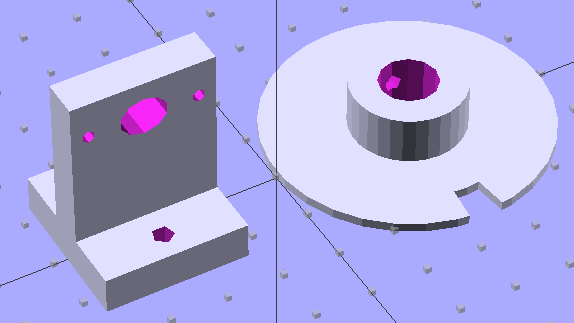
The wheel fits the shaft with a 4-40 setscrew to hold it in place. The post has 4-40 mounting holes for one of those optical switches, plus a big hole for the wiring. The solid models look about like you’d expect:
Wheel and post solid model
I located the post’s holes on the baseplate with a spindly pair of transfer punches, after transferring the wheel’s centerline by eyeballometric guesstimation:
Locating holes with transfer punches
Then aligned the baseplate on the Sherline, located the holes, and drilled ’em with manual CNC to get the proper spacing:
Drilling opto switch post holes
And then it went together quite smoothly:
Dyno with sync wheel
What’s really nice about 3D printing is you can build stuff like this without too much fuss & bother: figure out the solid model, walk gingerly through the software minefield, and (usually) assemble the parts later that day.
A bit of wiring to power the LED and pull up the phototransistor should do the trick.
The OpenSCAD code, including a few tweaks that rationalize spacings and sizes and suchlike:
My first pass at the NEMA 17 motor mount bracket used additive modeling, glomming together several blocks made from cube primitives:
The motor mounting plate, less five holes
Two side struts to stiffen the motor plate
The baseplate, minus two mounting holes
Makes perfect sense to me; perhaps I’m an additive kind of guy. That produced an OpenSCAD model with positive surfaces for the various parts and negative surfaces inside the holes:
NEMA 17 Mount – additive model
Compile that through CGAL, export as STL, inhale into RepG 25, and you (well, I) get what looks to be a fine object in the preview pane:
NEMA 17 RepG preview – additive
Then run it through Skeinforge 40, which emits a flurry of messages along these lines:
[19:11:08] Warning, the triangle mesh slice intersects itself in getLoopsFromCorrectMesh in triangle_mesh.
[19:11:08] Something will still be printed, but there is no guarantee that it will be the correct shape.
[19:11:08] Once the gcode is saved, you should check over the layer with a z of:
[19:11:09] 0.165
The usual searching suggested that sometimes Skeinforge has problems with coincident surfaces, such as between the motor mount plate and the struts and the base, or coincident edges where two blocks abut. Judging from the messages, the problem ran all the way to the top of the struts. Oddly, Skeinview didn’t show any problems, so the G-Code was (presumably) OK.
Error messages tend to make me twitchy, though. I modified the OpenSCAD code to extend the struts 0.1 mm inside the base and ran that model through the software stack, which produced not a single complaint about anything, anywhere.
Success!
However, painful experience has caused me to review the G-Code for every single object with the Skeinlayer plugin, which, right on cue, revealed this interesting anomaly:
NEMA 17 Mount – Skeinview – Bad gcode
That happened for every layer in the square motor mount plate: the lower right corner is fine, the upper left seems to be the negative of the actual solid model. The holes are filled, the plate is empty. The Skirt outline ignores the smaller holes, goes around the large one, and continues on its merry way.
I putzed around for a while and discovered that the failure seems acutely sensitive to the side strut thickness. Yeah, like that makes any sense.
Any variations along those lines that I tried generated either:
A flurry of mesh error messages, with seemingly good G-Code
No error messages whatsoever, with totally bogus G-Code
Running the STL files through netfabb Cloud Service produced the same diagnostic for both:
Number of holes: 3
Number of shells: 2
Mesh is not manifold and oriented.
 We unfortunately have not yet enough experience with the occuring server loads, that we can securely enable shell merging at the moment.
However, the repaired STL files produce correct G-Code: evidently OpenSCAD spits out bogus STL data. The fact that RepG/SF treats the two files differently suggests improved diagnostics would be in order, but that’s in the nature of fine tuning.
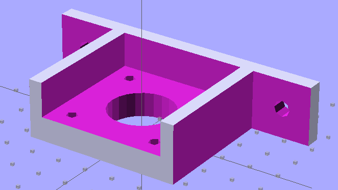
So I junked the additive model and went subtractive, chewing the recesses out of one huge block:
NEMA 17 Stepper Mount – solid model
That worked:
Number of holes: 0
Number of shells: 1
Mesh is manifold and oriented.
I like processes that don’t emit error messages or result in mysterious failures, although it’s not obvious that subtractive modeling will always produce correct results. Heck, I’m not sure I can think in terms of negative volumes all that well.
The OpenSCAD code for the additive model, with a highlight on the conditional that will trigger the two errors:
OpenSCAD depends on CGAL for all the 3D heavy lifting, which puts any STL export problems further upstream. I suppose I could open Yet Another RepG ticket to get better diagnostics, but the others haven’t gotten much attention so far and I suppose it’s not really their problem anyway.
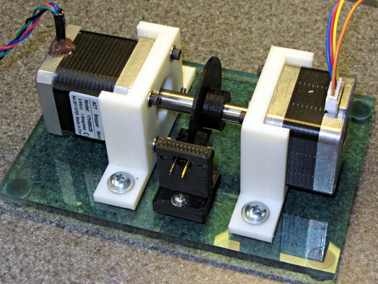
Combine two of those mounts with one of those couplers, add two NEMA 17 steppers (the one on the right is that one), slide a baseplate underneath, sprinkle with various screws, and shazam you get a stepper motor dynamometer:
Stepper Dynamometer
The baseplate puts the mounts 65 mm apart on the 10-32 screw centers, which is entirely a function of the coupler length, and is easy with manual CNC on the Sherline.
Changing the motors is straightforward: loosen coupler setscrew, remove base screws, slide motor away from coupler, remove mount screws. Won’t happen that often, methinks.
The general idea is to drive one stepper with a known current, apply a known resistive load to the other motor’s windings, and then plot torque vs. speed. It won’t be quite that simple, of course, but should produce some interesting data.
This simple cylinder connects two NEMA 17 stepper motors together:
Stepper Shaft Coupler
It’s quick-and-dirty:
Cut 2+ inches of 0.375 drill rod, face both ends
Drill #8 = 0.199 inch = 5.06 mm (because #9 = 0.196 inch = 4.98 mm is a bit too snug)
Cross-drill #41 in the Sherline (because #43 makes for stiff tapping)
Tap 4-40 for the setscrews
File off rough edges, run #8 drill through the bore to clean out tapping chips &c
Now, you probably don’t want to do this in real life, because you want a coupler with a bit of compliance to soak up the inevitable misalignment and dampen the mechanical resonances.
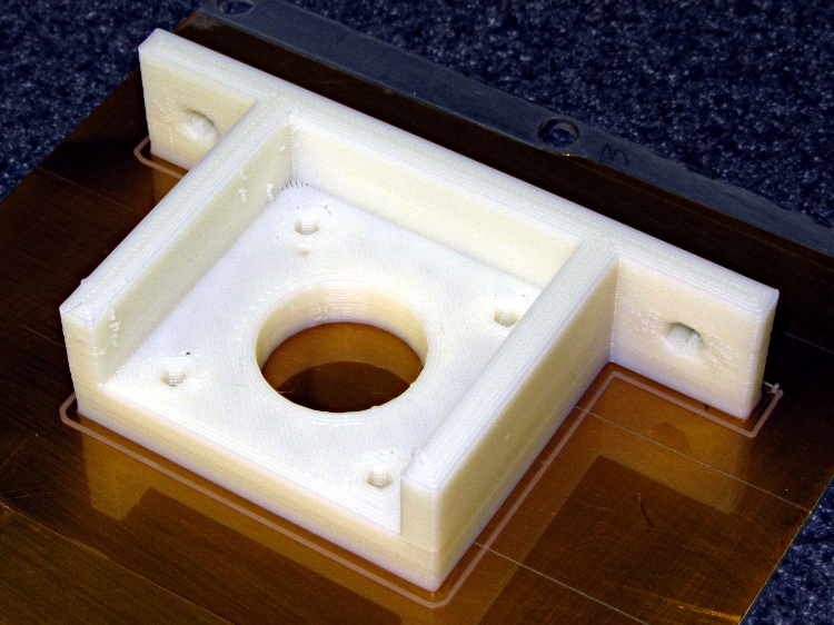
This mount will hold a NEMA 17 stepper firmly in place so I can attach things to the shaft:
NEMA 17 Mount on build plate
The baseplate holes fit 10-32 screws, which work in the plastic sheet that will go below this thing, and the motor mount plate holes fits 3 mm bolts for the motors. Washers under the heads, of course. Build with three additional shells, three solid layers, and 0.25 fill for useful rigidity; the flanges came out completely solid.
Somewhat to my surprise, this didn’t show any signs of delamination due to the rather low 190 °C extrusion temperature. The flanges aren’t all that massive, though, so perhaps trouble still lies await.
The OpenSCAD solid model uses subtractive construction, for reasons that I’ll go into later:
NEMA 17 Stepper Mount – solid model
The OpenSCAD source code:
// NEMA 17 stepper mount for dynamometer
// Ed Nisley KE4ZNU August 2011

include </home/ed/Thing-O-Matic/lib/MCAD/units.scad>

//-- Layout Control

Layout = "Build";				// Build Show

//-- Extrusion parameters

ThreadThick = 0.33;
ThreadWT = 2.0;
ThreadWidth = ThreadThick * ThreadWT;

HoleWindage = 0.3;			// enlarge hole dia by this amount

function IntegerMultiple(Size,Unit) = Unit * ceil(Size / Unit);

//-- Useful sizes

Tap10_32 = 0.159 * inch;
Clear10_32 = 0.190 * inch;
Head10_32 = 0.373 * inch;
Head10_32Thick = 0.110 * inch;
Nut10_32Dia = 0.433 * inch;
Nut10_32Thick = 0.130 * inch;

NEMA17_ShaftDia = 5.0;
NEMA17_ShaftLength = 24.0;
NEMA17_PilotDia = 0.866 * inch;
NEMA17_PilotLength = 0.080 * inch;
NEMA17_BCD = 1.725 * inch;
NEMA17_BoltDia = 3.5;
NEMA17_BoltOC = 1.220 * inch;

//-- Mount Sizes

MountWidth = IntegerMultiple(NEMA17_BCD,ThreadWidth);		// use BCD for motor clearance
MountThick = IntegerMultiple(8.0,ThreadThick);				// for stiffness

MountBoltDia = 3.0;

StandThick = IntegerMultiple(5.0,ThreadWidth);				// baseplate

StrutThick = IntegerMultiple(4.0,ThreadWidth);				// sides holding motor mount

UprightLength = MountWidth + 2*StrutThick;

StandBoltHead = IntegerMultiple(Head10_32,5);				// bolt head rounded up
StandBoltOC = IntegerMultiple(UprightLength + 2*StandBoltHead,5);

StandLength = StandBoltOC + 2*StandBoltHead;
StandWidth = IntegerMultiple(2*StandBoltHead,ThreadThick);

StandBoltClear = (StandLength - UprightLength)/2;			// flat around bolt head

MotorRecess = StandWidth - MountThick;

echo(str("Stand Base: ",StandLength," x ",StandWidth," x ",StandThick));
echo(str("Stand Bolt OC: ",StandBoltOC));
echo(str("Strut Thick: ",StrutThick));

//-- Convenience values

Protrusion = 0.1;		// make holes look good and joints intersect properly

BuildOffset = 3 * ThreadWidth;

//----------------------
// Useful routines

module PolyCyl(Dia,Height,ForceSides=0) {			// based on nophead's polyholes

  Sides = (ForceSides != 0) ? ForceSides : (ceil(Dia) + 2);

  FixDia = Dia / cos(180/Sides);

  cylinder(r=(FixDia + HoleWindage)/2,
           h=Height,
	   $fn=Sides);
}

module ShowPegGrid(Space = 10.0,Size = 1.0) {

  Range = floor(50 / Space);

	for (x=[-Range:Range])
	  for (y=[-Range:Range])
		translate([x*Space,y*Space,Size/2])
		  %cube(Size,center=true);

}

//----------------------
// Combined stand and mounting plate

module Combined() {

  difference() {
	translate([StandThick/2,0,StandWidth/2])
	  cube([(MountWidth + StandThick),StandLength,StandWidth],center=true);
	translate([-Protrusion/2,0,StandWidth - (MotorRecess - Protrusion)/2])
	  cube([(MountWidth + Protrusion),MountWidth,(MotorRecess + Protrusion)],center=true);
	translate([0,0,-Protrusion])				// pilot hole
	  PolyCyl(NEMA17_PilotDia,(MountThick + 2*Protrusion));
	for (x=[-1,1])								// motor bolt holes
	  for (y=[-1,1])
		translate([x*NEMA17_BoltOC/2,y*NEMA17_BoltOC/2,-Protrusion])
		  PolyCyl(MountBoltDia,(MountThick + 2*Protrusion));
	for (y=[-1,1])								// cutouts over bolts
	  translate([-Protrusion/2,
				y*((StandLength - StandBoltClear)/2 + Protrusion),
				StandWidth/2])
		cube([(MountWidth + Protrusion),
			 (StandBoltClear + Protrusion),
			 (StandWidth + 2*Protrusion)],center=true);
	for (y=[-1,1])								// stand bolt holes
	  translate([(MountWidth/2 - Protrusion),y*StandBoltOC/2,StandWidth/2])
		rotate([0,90,0])
		  PolyCyl(Clear10_32,StandThick + 2*Protrusion,8);

  }

}

//----------------------
// Lash everything together

ShowPegGrid();

if (Layout == "Build") {
  translate([0,0,0])
	Combined();
}

if (Layout == "Show") {
  translate([-StandWidth/2,0,(StandThick + MountWidth/2)])
	rotate([0,90,0])
	  Combined();
}
It would be handy, while doing the fast / coarse home stuff, to switch to G91 relative positioning mode and back off the switches by 2 mm by using a simple G0 X2 Y2 Z-2 that doesn’t depend on knowing the exact coordinates of the endpoint, but it seems relative positioning doesn’t work for any but the most trivial cases.
After some fiddling, this short routine produces a very fast, very long, fully coordinated XY move to some position in the +X +Y direction at the G1 X2 F100 command after the G91 command sets relative motions; it should move 2 mm away from the X switch. When the machine arrives at the new (unexpected) position, it then does the expected slow 2 mm Y and Z moves:
G21 (set units to mm)
G90 (set positioning to absolute)
(- coarse home axes)
G162 Z F1000 (home Z to get nozzle out of danger zone)
G161 Y F4000 (retract Y to get X out of front opening)
G161 X F4000 (now safe to home X)
(- back off switches)
G91
G1 X2 F100
G1 Y2 F100
G1 Z-2 F100
G90
I gave up and used an absolute move with hardcoded XYZ coordinates that should be pretty close to the stored values.