The Smell of Molten Projects in the Morning

Ed Nisley's Blog: Shop notes, electronics, firmware, machinery, 3D printing, laser cuttery, and curiosities. Contents: 100% human thinking, 0% AI slop.

Tag: CNC

Making parts with mathematics

  • Kicad-to-HAL: Mesa Electronics 5I25 FPGA Card

    Kicad-to-HAL: Mesa Electronics 5I25 FPGA Card

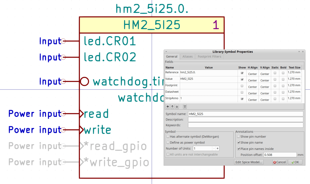
    The Mesa Electronics 5I25 FPGA card can implement a vast number of hardware I/O controllers, but I’ve only set up the few Kicad symbols required for my simple Sherline mill. The LinuxCNC hostmot2 doc gives the details.

    The hm2_5i25.0 component (upper right) carries the pins and functions pertaining to the card itself:

    Servo Thread Hookup schematic
    Servo Thread Hookup schematic

    If you have two such cards, you’ll also have an hm2_5i25.1 component. Kicad will annotate both with a zero, which Kicad-to-HAL then strips off before attaching the pin names.

    The read and write functions must attach to the first and last positions of the servo-thread component, respectively, to make the thing work correctly.

    The read_gpio and write_gpio functions are normally not connected; the * prefix suppresses a Kicad-to-HAL message about unconnected named pins. The code will strip the asterisk before connecting the pins, but that part is … lightly tested.

    Similarly, the schematic shows the watchdog output connected to one of the on-card LEDs. I’m not sure how to test that and wouldn’t see it inside the PC case; it might work as described.

    A hm2_5i25.0.gpio.000 Kicad symbol (middle) collects all of the HAL pins related to a single 5I25 GPIO pin; edit the three-digit pin identifier to match the hardware pin. Although the out and in names look backwards, they indicate the hardware direction: you write to the out pin and read from the in pin.

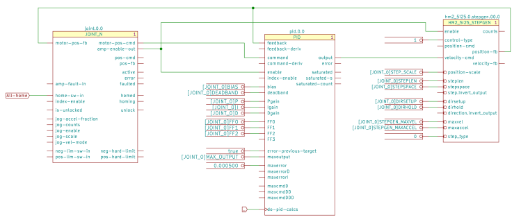
    The Sherline uses four stepgen blocks, so that’s the only other Kicad symbol on offer:

    X Axis Joint PID Stepgen schematic
    X Axis Joint PID Stepgen schematic

    The nets connecting those three components come directly from the LinuxCNC pncconf configuration utility. Fancier machines surely require more attention to the coefficient details.

    Connecting a true parameter to the step.invert_output and direction.invert_output pins flips the polarity of those signals. The pins are aliases of the corresponding GPIO invert_output pin, with the key advantage of not requiring you to figure out which GPIO pin corresponds to the FPGA’s output pin for each axis.

    The 5I25 card requires a pair of loadrt components to load the drivers and configure the FPGA:

    Kicad-to-HAL Demo Schematic
    Kicad-to-HAL Demo Schematic

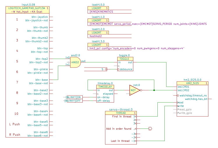
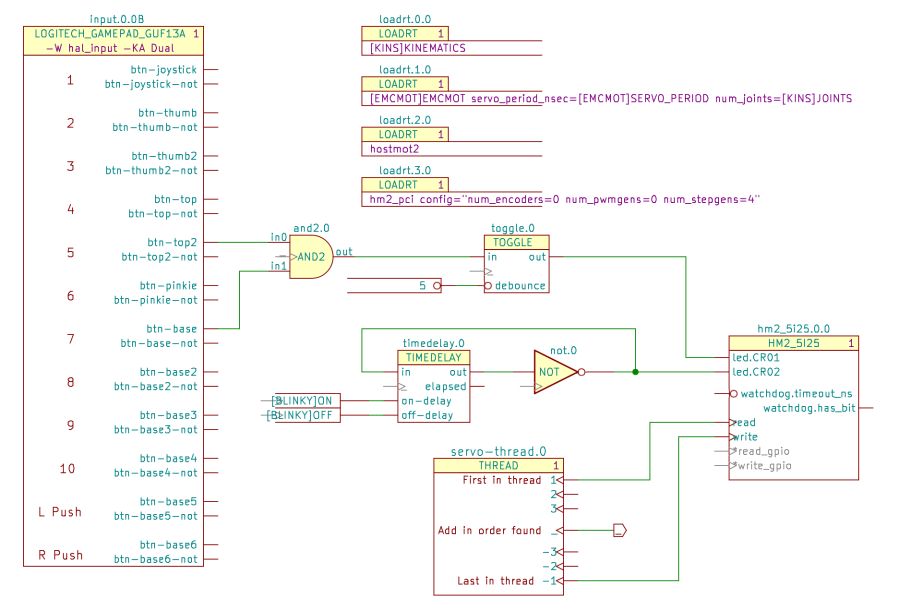
    The one-page demo schematic uses the same 5I25 configuration as the Sherline, with the LEDs driven by gamepad buttons to provide something to look at:

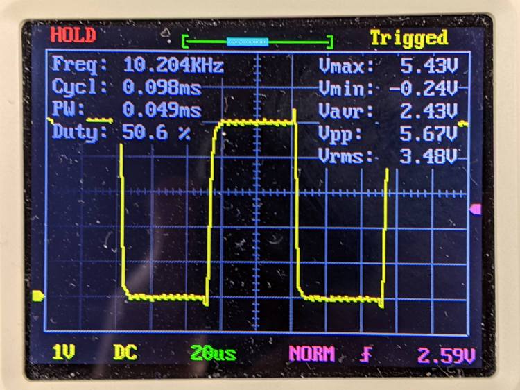
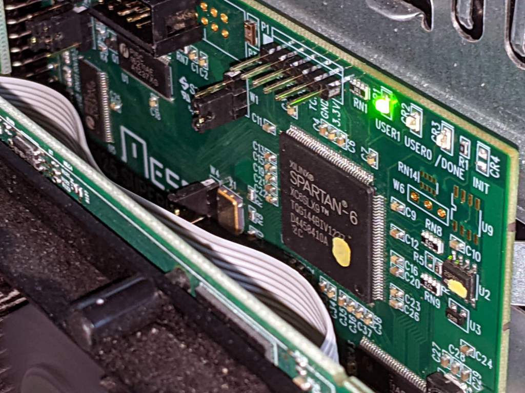
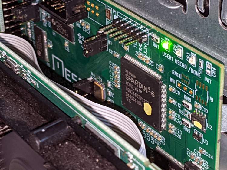
    Mesa 5I25 card - LED activity
    Mesa 5I25 card – LED activity

    I should force-fit an LED into the Sherline driver box just to have something easier to see.

  • Kicad-to-HAL: HALUI Components

    Kicad-to-HAL: HALUI Components

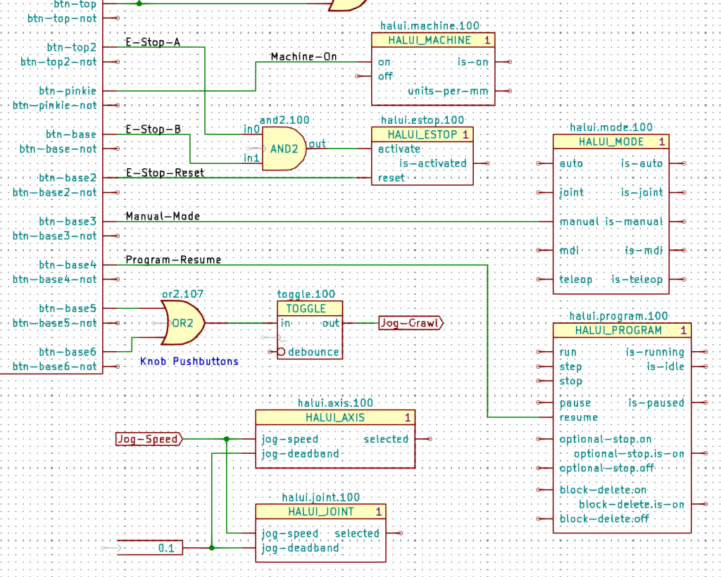
    The LinuxCNC HALUI “component” has so many pins that I divided them among about 18 Kicad symbols, each collecting the pins related to one function:

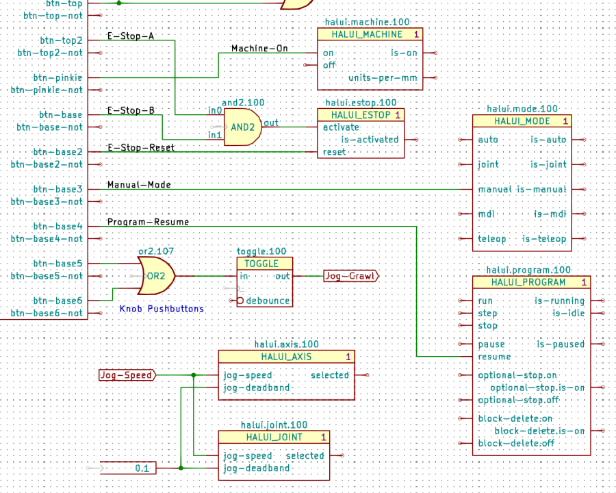
    Gamepad Button logic - HALUI components
    Gamepad Button logic – HALUI components

    The Kicad references (halui.mode.100) use periods as separators, not dashes, because HALUI runs automagically and has no thread functions.

    The symbol name (HALUI_MODE) serves as a unique identifier that should match the reference stem. I used underscores just for pretty, but it doesn’t make any difference.

    All of the Kicad symbols include the StripAnno field to remove the Kicad annotation, as described earlier. The Kicad annotations now start from 100, because I’m in the midst of tinkering an automagic way to produce the proper start-from-zero HAL numbering with everything properly sorted; this is very much a work in progress.

    So the full name of the resume pin on the HALUI_PROGRAM component sporting Kicad reference halui.program.100 is just:

    halui.program.resume

    This corresponds to the description of that pin in the HALUI doc, without a numeric identifier: there is only one HALUI.

    The net connecting the gamepad button to that pin:

    net _Gamepad_Buttons_Program-Resume <= input.0.btn-base4 => halui.program.resume
    

    A few more examples from the nets near the AND2 gate:

    net _Gamepad_Buttons_E-Stop-A <= input.0.btn-top2 => and2.0.in0
    net _Gamepad_Buttons_E-Stop-B <= input.0.btn-base => and2.0.in1
    net _Gamepad_Buttons_E-Stop-Reset <= input.0.btn-base2 => halui.estop.reset
    net _Gamepad_Buttons_Machine-On <= input.0.btn-pinkie => halui.machine.on
    net _Gamepad_Buttons_Manual-Mode <= input.0.btn-base3 => halui.mode.manual


    Some HALUI component references include numbers and letters identifying specific joints / axes / spindles, all of which you must edit as needed and none of which should be subjected to Kicad’s renumbering whims:

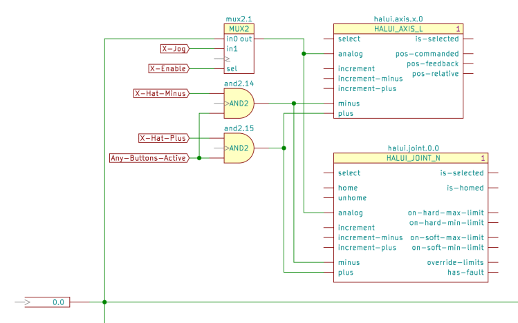
    X Axis jogging schematic
    X Axis jogging schematic

    The HAL commands producing the nets connecting the AND2 gates to the HALUI pins:

    net N_065 <= and2.14.out => halui.axis.x.minus halui.joint.0.minus
    net N_066 <= and2.15.out => halui.axis.x.plus halui.joint.0.plus
    

    The nets lack any specific name, so Kicad-to-HAL replaces Kicad’s default gibberish with the next integer from an ascending series. If your HAL configuration requires more than three digits worth of anonymous nets, feel free to tweak the format string.

  • Kicad-to-HAL: LoadUsr

    Kicad-to-HAL: LoadUsr

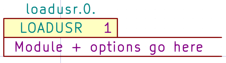
    The Kicad LOADUSR symbol puts its text directly into a HAL loadusr command:

    Kicad symbol - LOADUSR
    Kicad symbol – LOADUSR

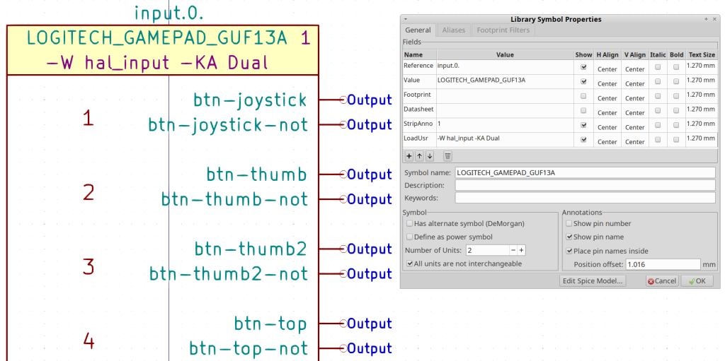
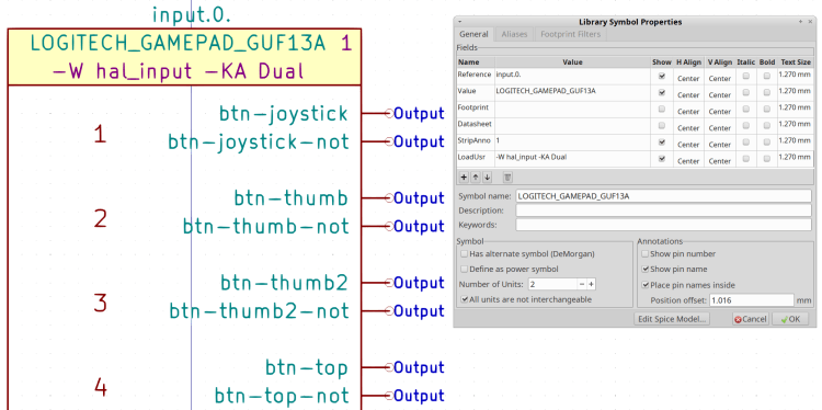
    Putting the same text in the LoadUsr field of a Kicad component may be tidier when there’s only one:

    Kicad Symbol Properties - Logitech gamepad
    Kicad Symbol Properties – Logitech gamepad

    The gamepad symbol in a schematic:

    Kicad-to-HAL Demo Schematic
    Kicad-to-HAL Demo Schematic

    Which produces this loadusr command in the HAL file:

    loadusr -W hal_input -KA Dual		# input.0.0
    

    You can edit the text after placing the Kicad component, so the symbol can contain placeholder text.

  • Kicad-to-HAL: Annotation Stripping

    Kicad-to-HAL: Annotation Stripping

    Kicad insists on annotating every component with a numeric suffix that can change depending on the sequence of components encountered during the annotation process. HAL, on the other hand, identifies multiple components using a numeric value as a suffix or embedded within the reference. HAL also has singleton components without a numeric value.

    A Moby Hack™ merges the two systems: Kicad will annotate each of its components, then Kicad-to-HAL can strip the annotation from the reference to form the HAL identifier.

    A Kicad component with a StripAnno field containing a “1” will trigger the stripping:

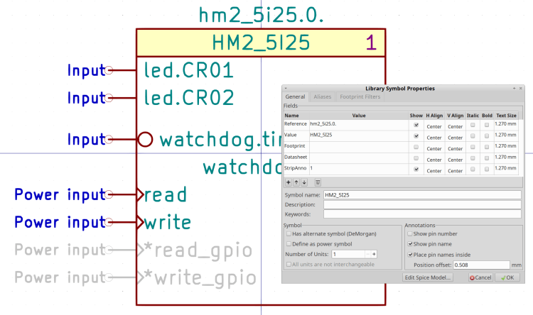
    Kicad Symbol Properties - HM2_5I25
    Kicad Symbol Properties – HM2_5I25

    The StripAnno digit (generally) appears to the right of the component name. A Kicad component without a StripAnno field or with the field containing anything other than “1” will pass its reference field directly into the HAL component.

    The Kicad reference for the HM2_5I25 component (center right) is hm2_5i25.0.0 and its stripped HAL reference is hm2_5i25.0:

    addf hm2_5i25.0.read		servo-thread
    

    The THREAD component (center bottom) is a singleton, because there will be only one component with a given thread name:

    Kicad symbol - THREAD
    Kicad symbol – THREAD

    The Kicad reference appends a zero to make servo-thread.0:

    Kicad-to-HAL Demo Schematic
    Kicad-to-HAL Demo Schematic

    The stripped HAL reference, as used in addf statements, is just servo-thread:

    addf and2.0		servo-thread
    addf constant.0		servo-thread
    addf constant.1		servo-thread
    addf not.0		servo-thread
    addf timedelay.0		servo-thread
    addf toggle.0		servo-thread
    

    Every Kicad symbol must have a reference ending with a period so Kicad-to-HAL can strip the trailing annotation value.

  • Kicad-to-HAL: Parameters and Constants

    Kicad-to-HAL: Parameters and Constants

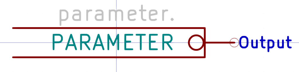
    Kicad PARAMETER symbols (center, left of the upper TOGGLE) provide the value for HAL setp commands:

    Kicad-to-HAL Demo Schematic
    Kicad-to-HAL Demo Schematic

    Which becomes this line in the HAL file:

    setp toggle.0.debounce 5	# parameter.0
    

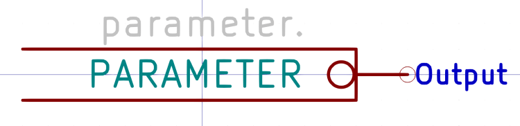
    Parameter pins use the Inverted graphic style decorating them with a small circle to distinguish parameters from ordinary data pins, but the data value is not inverted. Parameter components can also connect to ordinary HAL input pins without the Inverted style.

    PARAMETER symbols have an invisible reference value (parameter.0 in the example) that you don’t care about:

    Kicad symbol - PARAMETER
    Kicad symbol – PARAMETER

    Edit the value inside the symbol to whatever you need.

    Kicad CONSTANT symbols (lower center, left of the TIMEDELAY symbol) generate HAL CONSTANT modules, set their values, and connect them to a thread. The resulting HAL commands look like this:

    addf constant.0		servo-thread
    addf constant.1		servo-thread
    
    … snippage …
    
    setp constant.0.value [BLINKY]ON
    setp constant.1.value [BLINKY]OFF
    
    … snippage …
    
    net N_001 <= constant.1.out => timedelay.0.off-delay
    net N_002 <= constant.0.out => timedelay.0.on-delay
    

    The thread connections works the same way as for other HAL components with the automagic net connection to “_”:

    Kicad symbol - CONSTANT
    Kicad symbol – CONSTANT

    The (invisible) + in the middle tells Kicad-to-HAL to put the total number of CONSTANT components into the addf command.

    As with Parameters, edit the CONSTANT inside the symbol as needed.

    Both Parameters and Constants can use text values defined in the INI file:

    [BLINKY]
    ON = 0.2
    OFF = 2.0

    Both Parameters and Constants can connect to nets going to multiple input pins, but it’s probably not worth cluttering a schematic with off-page connectors just to reuse a single instance. When you copy-n-paste an otherwise identical symbol somewhere else, it will get a different reference number and generate additional HAL commands, which may offend your sense of neatness.

  • Kicad-to-HAL: Threads

    Kicad-to-HAL: Threads

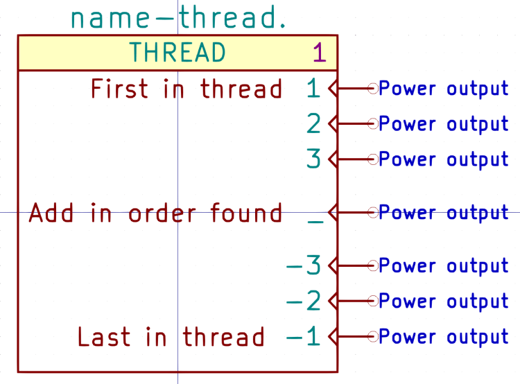
    The Kicad THREAD symbol (center bottom) creates the HAL addf commands connecting HAL component functions to the realtime threads:

    Kicad-to-HAL Demo Schematic
    Kicad-to-HAL Demo Schematic

    Change the Kicad reference to match the HAL thread name. AFAICT, you can use either servo-thread or base-thread, as defined by the LoadRT configuration (center top).

    Opinion: contemporary x86-64 PC architecture pretty much prevents running a base-thread at the pace required for step generation through a parallel port. In point of fact, I wrote Kicad-to-HAL specifically to configure a PC around a Mesa Electronics 5i25 FPGA controller for my Sherline CNC mill, as the real-time latency had regular glitches far exceeding the nominal 50 µs period. I suspect few new CNC installations will need a fast base thread.

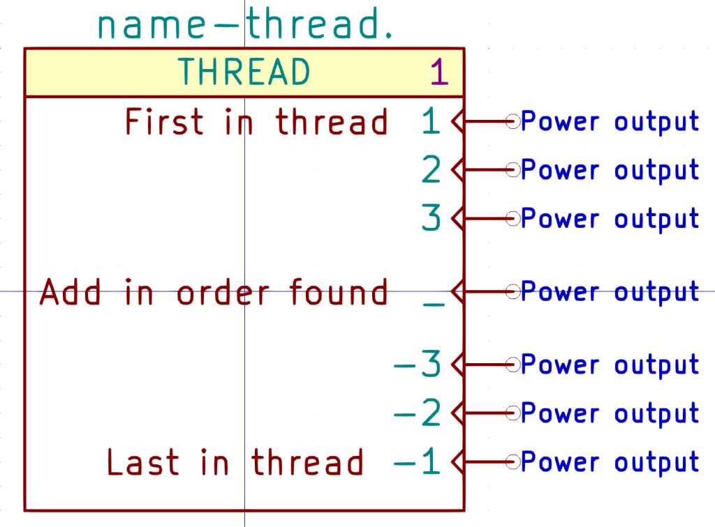
    The THREAD symbol has seven “Power output” pins drawn in the Clock graphic style:

    Kicad symbol - THREAD
    Kicad symbol – THREAD

    Kicad-to-HAL finds the other components attached to each pin and generates addf commands:

    #------
    # Function hookups
    
    # Position: 1
    
    addf hm2_5i25.0.read		servo-thread
     
    # Position: _
    
    addf and2.0		servo-thread
    addf constant.0		servo-thread
    addf constant.1		servo-thread
    addf not.0		servo-thread
    addf timedelay.0		servo-thread
    addf toggle.0		servo-thread
     
    # Position: -1
    
    addf hm2_5i25.0.write		servo-thread
    

    FiXME: Contrary to the comment in the symbol, addf commands for each pin come out sorted by reference.

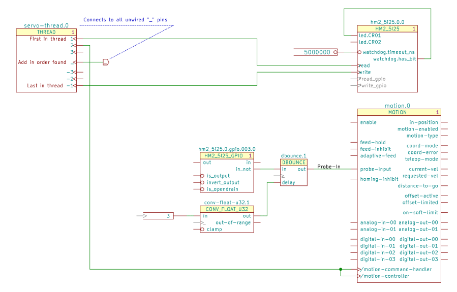
    The Mesa hostmot2 HAL component (middle right in the first screenshot) generates several function names that don’t require connections, but Kicad-to-HAL produces a warning for single-pin (i.e. unconnected) nets with non-default names. Prefix the pin name with an asterisk (*read-gpio) to suppress the error message.

    The motion HAL component (lower right below) has functions that do not follow the normal naming convention:

    Servo Thread Hookup schematic
    Servo Thread Hookup schematic

    Prefix the Kicad pin name with a slash (/motion-controller) to tell Kicad-to-HAL to use the name without the standard motion. prefix:
    # Position: 2
    
    addf motion-command-handler		servo-thread
    addf motion-controller		servo-thread
    

    Perhaps they were supposed to be motion.command-handler and motion.controller, but it’s too late to change? If so, I know that feeling.

    Other quirks surely lurk within other HAL components, but, on the whole, this seems to work pretty well.

  • Kicad-to-HAL: LoadRT

    Kicad-to-HAL: LoadRT

    Each Kicad LOADRT symbol (upper right):

    Kicad-to-HAL Demo Schematic
    Kicad-to-HAL Demo Schematic

    produces a corresponding HAL loadrt command:

    loadrt [KINS]KINEMATICS		# loadrt.0.0
    loadrt [EMCMOT]EMCMOT servo_period_nsec=[EMCMOT]SERVO_PERIOD num_joints=[KINS]JOINTS		# loadrt.1.0
    loadrt hostmot2		# loadrt.2.0
    loadrt hm2_pci config="num_encoders=0 num_pwmgens=0 num_stepgens=4"		# loadrt.3.0
    

    Symbols with a (typically not-visble) + in their LoadRT field generate matching loadrt commands with the total number of identical symbols:

    loadrt and2 count=1<br>loadrt constant count=2<br>loadrt not count=1<br>loadrt timedelay count=1<br>loadrt toggle count=1
    

    Kicad symbols may have additional text after the (typically visible) + sign, as in the LOGIC symbol:

    Gamepad Valid schematic
    Gamepad Valid schematic

    Kicad-to-HAL will concatenate the text, in reference order, into the loadrt command:

    loadrt logic		count=1 personality=0x804
    

    The LOGIC symbol shows how that works:

    Kicad symbol - LOGIC
    Kicad symbol – LOGIC

    Edit the LoadRT field text as needed for each Kicad component, with subsequent blocks omitting the personality= and including a leading comma:

    + ,0x1004
    

    Because the order of the symbols matters, the symbol reference includes a number (the 0 in the symbol reference field) that you must edit by hand for each new schematic component, because the Kicad annotation tacked on the end will change every time you generate new annotations.

    The current version of Kicad-to-HAL sorts schematic references alphanumerically, so if you have more than ten LOGIC symbols with concatenated text, it won’t work: FIXME. Maybe annotating with Kicad numbers starting at 100, then subtracting 100 to get the HAL numbers would be simpler?

    Update: Yes, numbering from 100 works fine, along with automagically finding the lowest annotation and subtracting it. Upcoming snippets will show both ways.

    The Kicad LOGIC symbol has eight input pins and all five possible output pins, despite what the configuration value may create in the corresponding HAL function. As long as you don’t connect anything to the undefined inputs and outputs, Kicad turns them into one-pin anonymous nets which Kicad-to-HAL weeds out of the HAL file.

    The demo schematic as a GitHub Gist:

    EESchema Schematic File Version 4
    EELAYER 30 0
    EELAYER END
    $Descr USLetter 11000 8500
    encoding utf-8
    Sheet 1 1
    Title "Kicad-to-HAL Demo Schematic"
    Date "2021-03-23"
    Rev ""
    Comp "Ed Nisley – KE4ZNU"
    Comment1 ""
    Comment2 ""
    Comment3 ""
    Comment4 ""
    $EndDescr
    $Comp
    L LinuxCNC-HAL:THREAD servo-thread.0
    U 1 1 6059ED1C
    P 5650 5200
    F 0 "servo-thread.0" H 5650 5750 59 0000 C CNN
    F 1 "THREAD" H 5650 5650 50 0000 C CNN
    F 2 "" H 5750 5300 50 0001 C CNN
    F 3 "" H 5750 5300 50 0001 C CNN
    F 4 "1" H 6050 5650 50 0000 C CNN "StripAnno"
    1 5650 5200
    1 0 0 -1
    $EndComp
    $Comp
    L LinuxCNC-HAL:LOGITECH_GAMEPAD_GUF13A input.0.0
    U 2 1 605A12D7
    P 3000 3500
    F 0 "input.0.0" H 3000 5350 50 0000 C CNN
    F 1 "LOGITECH_GAMEPAD_GUF13A" H 2950 5250 50 0000 C CNN
    F 2 "" H 8500 7100 50 0001 C CNN
    F 3 "" H 8500 7100 50 0001 C CNN
    F 4 "1" H 3550 5250 50 0000 C CNN "StripAnno"
    F 5 "-W hal_input -KA Dual" H 2950 5150 50 0000 C CNN "LoadUsr"
    2 3000 3500
    1 0 0 -1
    $EndComp
    $Comp
    L LinuxCNC-HAL:AND2 and2.0
    U 1 1 605A4CD8
    P 4350 3300
    F 0 "and2.0" H 4350 3500 50 0000 C CNN
    F 1 "AND2" H 4350 3300 50 0000 C CNN
    F 2 "" H 4350 3300 50 0001 C CNN
    F 3 "" H 4350 3300 50 0001 C CNN
    F 4 "+" H 4350 3300 50 0001 C CNN "LoadRT"
    1 4350 3300
    1 0 0 -1
    $EndComp
    Wire Wire Line
    3700 3800 3850 3800
    Wire Wire Line
    3850 3800 3850 3400
    Wire Wire Line
    3850 3400 4050 3400
    Wire Wire Line
    4050 3200 3700 3200
    $Comp
    L LinuxCNC-HAL:TOGGLE toggle.0
    U 1 1 605A7FF1
    P 5750 3400
    F 0 "toggle.0" H 5750 3700 50 0000 C CNN
    F 1 "TOGGLE" H 5750 3600 50 0000 C CNN
    F 2 "" H 6050 3350 50 0001 C CNN
    F 3 "" H 6050 3350 50 0001 C CNN
    F 4 "+" H 5750 3400 50 0001 C CNN "LoadRT"
    1 5750 3400
    1 0 0 -1
    $EndComp
    $Comp
    L LinuxCNC-HAL:PARAMETER parameter.0
    U 1 1 605A8894
    P 4950 3500
    F 0 "parameter.0" H 4950 3600 50 0001 C CNN
    F 1 "5" H 5150 3500 50 0000 R CNN
    F 2 "" H 5250 3500 50 0001 C CNN
    F 3 "" H 5250 3500 50 0001 C CNN
    1 4950 3500
    1 0 0 -1
    $EndComp
    $Comp
    L LinuxCNC-HAL:HM2_5I25 hm2_5i25.0.0
    U 1 1 605A8E84
    P 7700 4300
    F 0 "hm2_5i25.0.0" H 7700 4800 50 0000 C CNN
    F 1 "HM2_5I25" H 7700 4700 50 0000 C CNN
    F 2 "" H 8250 4100 50 0001 C CNN
    F 3 "" H 8250 4100 50 0001 C CNN
    F 4 "1" H 8100 4700 50 0000 C CNN "StripAnno"
    1 7700 4300
    1 0 0 -1
    $EndComp
    Wire Wire Line
    4650 3300 5450 3300
    Wire Wire Line
    5350 3500 5500 3500
    Wire Wire Line
    6100 3300 6950 3300
    Wire Wire Line
    7150 4550 6900 4550
    Wire Wire Line
    6900 4550 6900 5550
    Wire Wire Line
    6900 5550 6200 5550
    $Comp
    L LinuxCNC-HAL:LOADRT loadrt.3.?
    U 1 1 605AF190
    P 5000 2950
    AR Path="/6047689B/605AF190" Ref="loadrt.3.?" Part="1"
    AR Path="/605AF190" Ref="loadrt.3.0" Part="1"
    F 0 "loadrt.3.0" H 5000 3200 50 0000 C CNN
    F 1 "LOADRT" H 4950 3100 50 0000 C CNN
    F 2 "" H 5800 2450 50 0001 C CNN
    F 3 "https://linuxcnc.org/docs/2.8/html/hal/basic-hal.html#_loadrt&quot; H 5800 2450 50 0001 C CNN
    F 4 "hm2_pci config=\"num_encoders=0 num_pwmgens=0 num_stepgens=4\"" H 4750 3000 50 0000 L CNN "LoadRT"
    F 5 "1" H 5250 3100 50 0000 C CNN "StripAnno"
    1 5000 2950
    1 0 0 -1
    $EndComp
    $Comp
    L LinuxCNC-HAL:LOADRT loadrt.2.?
    U 1 1 605AF198
    P 5000 2600
    AR Path="/6047689B/605AF198" Ref="loadrt.2.?" Part="1"
    AR Path="/605AF198" Ref="loadrt.2.0" Part="1"
    F 0 "loadrt.2.0" H 5000 2850 50 0000 C CNN
    F 1 "LOADRT" H 4950 2750 50 0000 C CNN
    F 2 "" H 5800 2100 50 0001 C CNN
    F 3 "https://linuxcnc.org/docs/2.8/html/hal/basic-hal.html#_loadrt&quot; H 5800 2100 50 0001 C CNN
    F 4 "hostmot2" H 4750 2650 50 0000 L CNN "LoadRT"
    F 5 "1" H 5250 2750 50 0000 C CNN "StripAnno"
    1 5000 2600
    1 0 0 -1
    $EndComp
    Text GLabel 6450 5200 2 50 Output ~ 0
    _
    $Comp
    L LinuxCNC-HAL:LOADRT loadrt.0.?
    U 1 1 605B697F
    P 5000 1900
    AR Path="/6047689B/605B697F" Ref="loadrt.0.?" Part="1"
    AR Path="/605B697F" Ref="loadrt.0.0" Part="1"
    F 0 "loadrt.0.0" H 5000 2150 50 0000 C CNN
    F 1 "LOADRT" H 4950 2050 50 0000 C CNN
    F 2 "" H 5800 1400 50 0001 C CNN
    F 3 "https://linuxcnc.org/docs/2.8/html/hal/basic-hal.html#_loadrt&quot; H 5800 1400 50 0001 C CNN
    F 4 "[KINS]KINEMATICS" H 4750 1950 50 0000 L CNN "LoadRT"
    F 5 "1" H 5250 2050 50 0000 C CNN "StripAnno"
    1 5000 1900
    1 0 0 -1
    $EndComp
    $Comp
    L LinuxCNC-HAL:LOADRT loadrt.1.?
    U 1 1 605B6987
    P 5000 2250
    AR Path="/6047689B/605B6987" Ref="loadrt.1.?" Part="1"
    AR Path="/605B6987" Ref="loadrt.1.0" Part="1"
    F 0 "loadrt.1.0" H 5000 2500 50 0000 C CNN
    F 1 "LOADRT" H 4950 2400 50 0000 C CNN
    F 2 "" H 5800 1750 50 0001 C CNN
    F 3 "https://linuxcnc.org/docs/2.8/html/hal/basic-hal.html#_loadrt&quot; H 5800 1750 50 0001 C CNN
    F 4 "[EMCMOT]EMCMOT servo_period_nsec=[EMCMOT]SERVO_PERIOD num_joints=[KINS]JOINTS" H 4750 2300 50 0000 L CNN "LoadRT"
    F 5 "1" H 5250 2400 50 0000 C CNN "StripAnno"
    1 5000 2250
    1 0 0 -1
    $EndComp
    Wire Wire Line
    6200 5200 6450 5200
    Wire Wire Line
    6700 4450 7150 4450
    Wire Wire Line
    6700 4450 6700 4850
    Wire Wire Line
    6700 4850 6200 4850
    $Comp
    L LinuxCNC-HAL:TIMEDELAY timedelay.0
    U 1 1 605C692D
    P 5200 4250
    F 0 "timedelay.0" H 5200 4600 50 0000 C CNN
    F 1 "TIMEDELAY" H 5200 4500 50 0000 C CNN
    F 2 "" H 5200 4400 50 0001 C CNN
    F 3 "" H 5200 4400 50 0001 C CNN
    F 4 "+" H 5200 4250 50 0001 C CNN "LoadRT"
    1 5200 4250
    1 0 0 -1
    $EndComp
    $Comp
    L LinuxCNC-HAL:CONSTANT constant.0
    U 1 1 605C7C1F
    P 4350 4300
    F 0 "constant.0" H 4350 4400 50 0001 C CNN
    F 1 "[BLINKY]ON" H 4500 4300 50 0000 R CNN
    F 2 "" H 4600 4050 50 0001 C CNN
    F 3 "" H 4600 4050 50 0001 C CNN
    F 4 "+" H 4350 4300 50 0001 C CNN "LoadRT"
    1 4350 4300
    1 0 0 -1
    $EndComp
    $Comp
    L LinuxCNC-HAL:CONSTANT constant.1
    U 1 1 605C822C
    P 4350 4400
    F 0 "constant.1" H 4350 4500 50 0001 C CNN
    F 1 "[BLINKY]OFF" H 4500 4400 50 0000 R CNN
    F 2 "" H 4600 4150 50 0001 C CNN
    F 3 "" H 4600 4150 50 0001 C CNN
    F 4 "+" H 4350 4400 50 0001 C CNN "LoadRT"
    1 4350 4400
    1 0 0 -1
    $EndComp
    Wire Wire Line
    4750 4300 4850 4300
    Wire Wire Line
    4750 4400 4850 4400
    Wire Wire Line
    7150 4000 6950 4000
    Wire Wire Line
    6950 4000 6950 3300
    $Comp
    L LinuxCNC-HAL:NOT not.0
    U 1 1 605D425F
    P 6000 4100
    F 0 "not.0" H 6100 4250 50 0000 C CNN
    F 1 "NOT" H 6000 4100 50 0000 C CNN
    F 2 "" H 6350 3850 50 0001 C CNN
    F 3 "" H 6350 3850 50 0001 C CNN
    F 4 "+" H 6000 4100 50 0001 C CNN "LoadRT"
    1 6000 4100
    1 0 0 -1
    $EndComp
    Wire Wire Line
    5550 4100 5750 4100
    Wire Wire Line
    6450 4100 6600 4100
    Wire Wire Line
    6600 4100 6600 3800
    Wire Wire Line
    6600 3800 4700 3800
    Wire Wire Line
    4700 3800 4700 4100
    Wire Wire Line
    4700 4100 4850 4100
    Wire Wire Line
    6600 4100 7150 4100
    Connection ~ 6600 4100
    $EndSCHEMATC
    [EMCMOT]
    EMCMOT = motmod
    COMM_TIMEOUT = 1.0
    SERVO_PERIOD = 1000000
    [KINS]
    JOINTS = 4
    KINEMATICS = trivkins coordinates=XYZA
    [BLINKY]
    ON = 0.2
    OFF = 2.0
    view raw machine.ini hosted with ❤ by GitHub
    # LinuxCNC HAL file
    # Kicad netlist: LinuxCNC Test Schematic.xml
    # Tue 23 Mar 2021 10:47:04 AM EDT
    #——
    # LoadRT modules
    loadrt [KINS]KINEMATICS # loadrt.0.0
    loadrt [EMCMOT]EMCMOT servo_period_nsec=[EMCMOT]SERVO_PERIOD num_joints=[KINS]JOINTS # loadrt.1.0
    loadrt hostmot2 # loadrt.2.0
    loadrt hm2_pci config="num_encoders=0 num_pwmgens=0 num_stepgens=4" # loadrt.3.0
    loadrt and2 count=1
    loadrt constant count=2
    loadrt not count=1
    loadrt timedelay count=1
    loadrt toggle count=1
    #——
    # LoadUsr modules
    loadusr -W hal_input -KA Dual # input.0.0
    #——
    # Function hookups
    # Position: 1
    addf hm2_5i25.0.read servo-thread
    # Position: _
    addf and2.0 servo-thread
    addf constant.0 servo-thread
    addf constant.1 servo-thread
    addf not.0 servo-thread
    addf timedelay.0 servo-thread
    addf toggle.0 servo-thread
    # Position: -1
    addf hm2_5i25.0.write servo-thread
    #——
    # Parameters
    setp toggle.0.debounce 5 # parameter.0
    #——
    # Constants
    setp constant.0.value [BLINKY]ON
    setp constant.1.value [BLINKY]OFF
    #——
    # Nets
    net N_001 <= constant.1.out => timedelay.0.off-delay
    net N_002 <= constant.0.out => timedelay.0.on-delay
    net N_003 <= not.0.out => hm2_5i25.0.led.CR02 timedelay.0.in
    net N_004 <= toggle.0.out => hm2_5i25.0.led.CR01
    net N_006 <= and2.0.out => toggle.0.in
    net N_007 <= timedelay.0.out => not.0.in
    net N_008 <= input.0.btn-top2 => and2.0.in0
    net N_009 <= input.0.btn-base => and2.0.in1
    #——
    # Done!