|
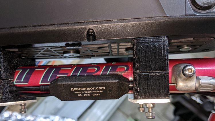
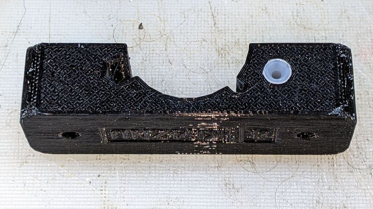
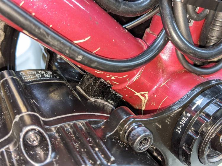
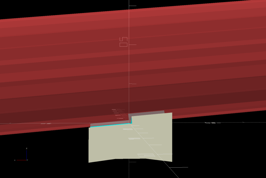
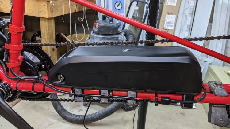
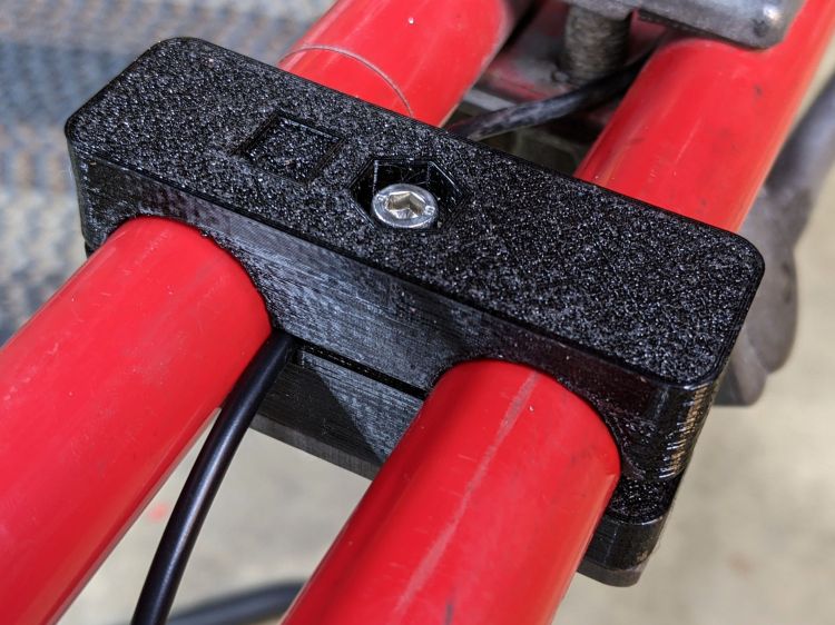
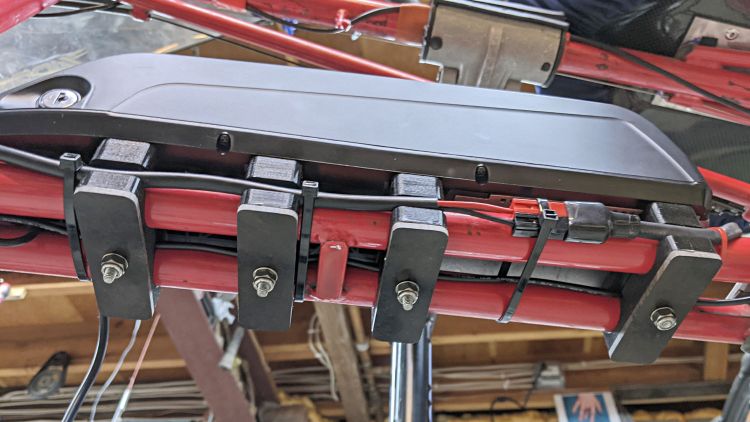
// Tour Easy Bafang Battery Mount |
|
// Ed Nisley KE4ZNU 2021-04 |
|
|
|
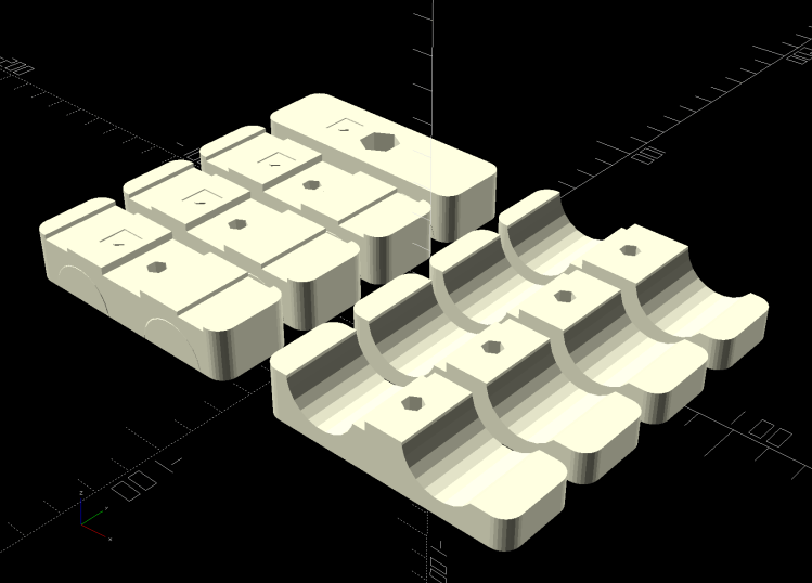
Layout = "Build"; // [Frame,Block,Show,Build,Bushing,Cateye] |
|
|
|
FrameWidths = [60.8,62.0,63.4,66.7]; // last = rear overhang support block |
|
|
|
Support = true; |
|
|
|
//- Extrusion parameters must match reality! |
|
|
|
/* [Hidden] */ |
|
|
|
ThreadThick = 0.25; |
|
ThreadWidth = 0.40; |
|
|
|
HoleWindage = 0.2; |
|
|
|
Protrusion = 0.1; // make holes end cleanly |
|
|
|
inch = 25.4; |
|
|
|
function IntegerMultiple(Size,Unit) = Unit * ceil(Size / Unit); |
|
|
|
ID = 0; |
|
OD = 1; |
|
LENGTH = 2; |
|
|
|
|
|
//———- |
|
// Dimensions |
|
// Bike frame lies along X axis, rear to +X |
|
|
|
FrameTube = [350,22.6 + HoleWindage,22.6 + HoleWindage]; // X = longer than anything else |
|
|
|
FrameAngle = atan((65.8 – 59.4)/300); // measured distances = included angle between tubes |
|
TubeAngle = FrameAngle/2; // .. frame axis to tube |
|
|
|
FrameSides = 24; |
|
|
|
echo(str("Frame angle: ",FrameAngle)); |
|
|
|
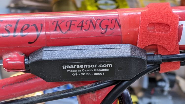
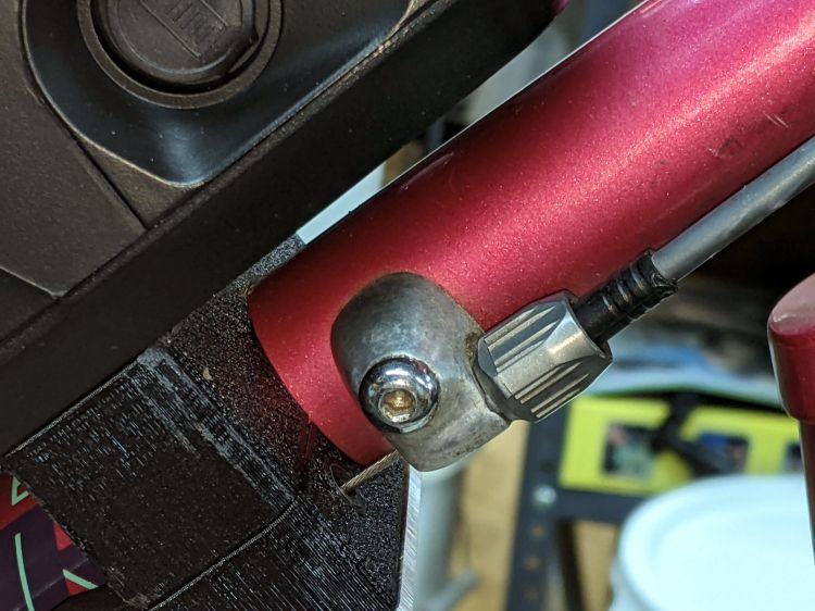
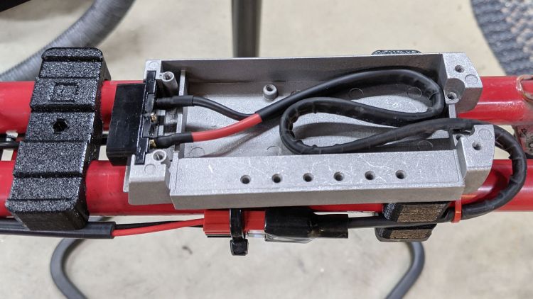
SpeedOD = 3.5; // speed sensor cable along frame |
|
|
|
PowerOD = 6.7; // power cable between frame tubes |
|
|
|
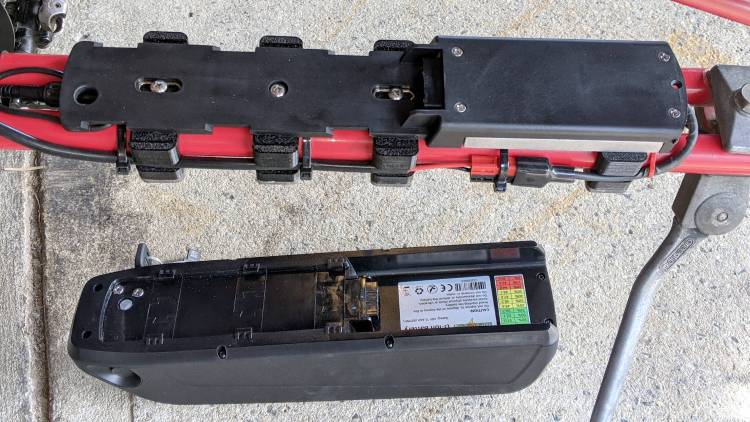
BatteryBoss = [5.5,16.0,2.5]; // battery mount boss, center is round |
|
BossSlotOAL = 32.0; // .. end bosses are elongated |
|
BossOC = 65.0; // .. along length of mount |
|
|
|
LatchWidth = 10.0; // battery latches to mount plate |
|
LatchThick = 1.5; |
|
LatchOC = 56.0; |
|
|
|
WallThick = 5.0; // thinnest wall |
|
|
|
Block = [25.0,78.0,FrameTube.z + 2*WallThick]; // must be larger than frame tube spacing |
|
echo(str("Block: ",Block)); |
|
|
|
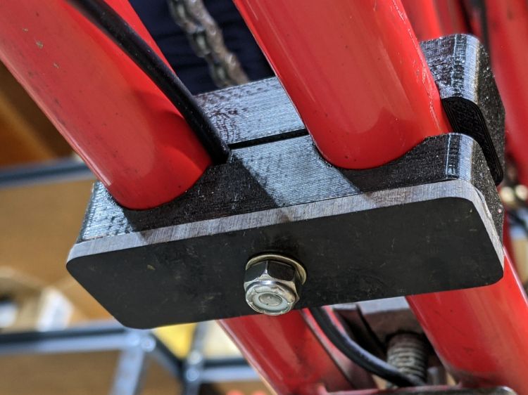
// M5 SHCS nyloc nut |
|
Screw = [5.0,8.5,5.0]; // OD, LENGTH = head |
|
Washer = [5.5,10.1,1.0]; |
|
Nut = [5.0,9.0,5.0]; |
|
|
|
// 10-32 Philips nyloc nut |
|
Screw10 = [5.2,9.8,3.6]; // OD, LENGTH = head |
|
Washer10 = [5.5,11.0,1.0]; |
|
Nut10 = [5.2,10.7,6.2]; |
|
|
|
Kerf = 1.0; // cut through middle to apply compression |
|
|
|
CornerRadius = 5.0; |
|
|
|
EmbossDepth = 2*ThreadThick; // lettering depth |
|
|
|
//———————- |
|
// Useful routines |
|
|
|
module PolyCyl(Dia,Height,ForceSides=0) { // based on nophead's polyholes |
|
Sides = (ForceSides != 0) ? ForceSides : (ceil(Dia) + 2); |
|
FixDia = Dia / cos(180/Sides); |
|
cylinder(d=(FixDia + HoleWindage),h=Height,$fn=Sides); |
|
} |
|
|
|
|
|
|
|
// clamp overall shape |
|
|
|
module ClampBlock() { |
|
difference() { |
|
hull() |
|
for (i=[-1,1], j=[-1,1]) |
|
translate([i*(Block.x/2 – CornerRadius),j*(Block.y/2 – CornerRadius),-Block.z/2]) |
|
cylinder(r=CornerRadius,h=Block.z,$fn=4*8); |
|
|
|
translate([0,0,-(Block.z/2 + Protrusion)]) |
|
rotate(0*180/6) |
|
PolyCyl(Screw[ID],Block.z + 2*Protrusion,6); |
|
|
|
cube([2*Block.x,2*Block.y,Kerf],center=true); |
|
|
|
translate([0,-(Block.y/2 – PowerOD + Protrusion/2),-PowerOD/2]) |
|
cube([2*Block.x,2*PowerOD + Protrusion,PowerOD],center=true); |
|
|
|
} |
|
|
|
} |
|
|
|
// frame tube layout with measured side-to-side width |
|
|
|
module Frame(Outer = FrameWidths[0],AdjustDia = 0.0) { |
|
|
|
TubeOC = Outer – FrameTube.y/cos(TubeAngle); // increase dia for angle |
|
|
|
for (i=[-1,1]) |
|
translate([0,i*TubeOC/2,0]) |
|
rotate([0,90,i*TubeAngle]) rotate(180/FrameSides) |
|
cylinder(d=FrameTube.z + AdjustDia,h=FrameTube.x,center=true,$fn=FrameSides); |
|
} |
|
|
|
// complete clamp block |
|
|
|
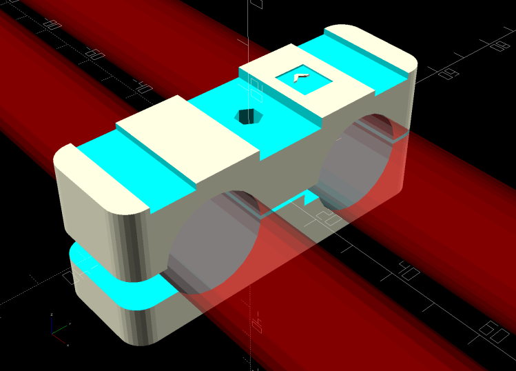
module Clamp(Outer = FrameWidths[0]) { |
|
|
|
TubeOC = Outer – FrameTube.y/cos(TubeAngle); // increase dia for angle |
|
|
|
difference() { |
|
ClampBlock(); |
|
Frame(Outer); |
|
|
|
translate([0,(TubeOC/2 – FrameTube[OD]/2),-SpeedOD/2]) |
|
cube([2*Block.x,2*SpeedOD,SpeedOD],center=true); |
|
|
|
translate([0,15,Block.z/2 – EmbossDepth/2 + Protrusion]) |
|
cube([9.0,8,EmbossDepth],center=true); |
|
translate([0,22,-Block.z/2 + EmbossDepth/2 – Protrusion]) |
|
cube([9.0,26,EmbossDepth],center=true); |
|
|
|
if (Outer == FrameWidths[len(FrameWidths) – 1]) { // special rear block |
|
translate([0,0,Block.z/2 – 2*Screw10[LENGTH]]) |
|
PolyCyl(Washer10[OD],2*Screw10[LENGTH] + Protrusion,6); |
|
} |
|
else { // other blocks have channels |
|
translate([0,0,Block.z/2 – BatteryBoss[LENGTH]/2 + Protrusion]) |
|
cube([BossSlotOAL,BatteryBoss[OD],BatteryBoss[LENGTH] + Protrusion],center=true); |
|
|
|
for (i=[-1,1]) |
|
translate([0,i*LatchOC/2,Block.z/2 – LatchThick/2 + Protrusion]) |
|
cube([BossSlotOAL,LatchWidth,LatchThick + Protrusion],center=true); |
|
} |
|
} |
|
|
|
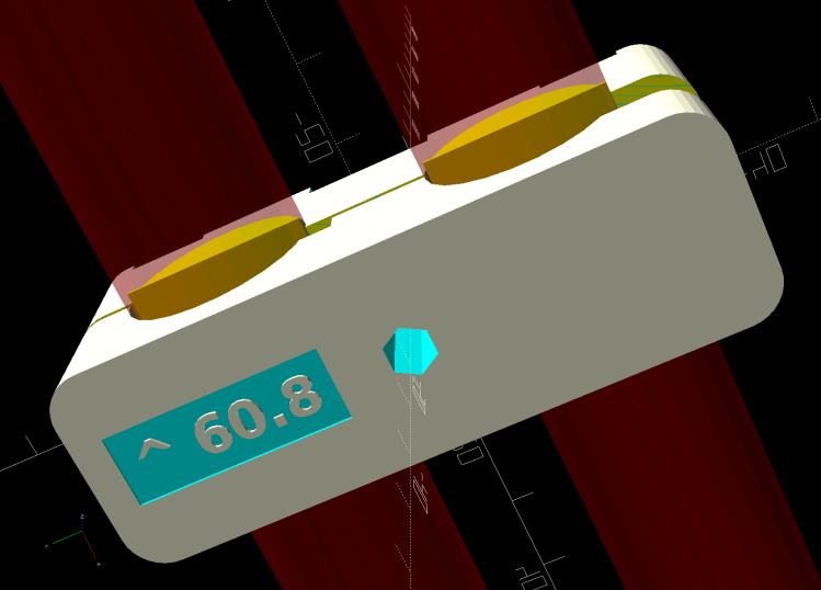
translate([0,15,Block.z/2 – EmbossDepth]) |
|
linear_extrude(height=EmbossDepth) |
|
rotate(90) |
|
text(text="^",size=5,spacing=1.00,font="Bitstream Vera Sans:style=Bold", |
|
halign="center",valign="center"); |
|
|
|
translate([0,22,-Block.z/2]) |
|
linear_extrude(height=EmbossDepth) |
|
rotate(-90) mirror([0,1,0]) |
|
text(text=str("^ ",Outer),size=4.5,spacing=1.00,font="Bitstream Vera Sans:style=Bold", |
|
halign="center",valign="center"); |
|
|
|
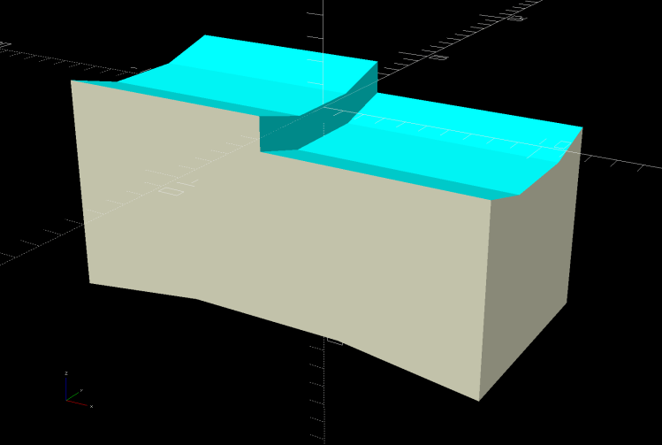
if (Support) |
|
color("Yellow") { |
|
NumRibs = 7; |
|
RibOC = Block.x/(NumRibs – 1); |
|
intersection() { |
|
translate([0,0,Block.z/2 + Kerf/2]) |
|
cube([2*Block.x,2*Block.y,Block.z],center=true); |
|
union() for (j=[-1,1]) { |
|
translate([0,j*TubeOC/2,Kerf/2]) |
|
cube([1.1*Block.x,FrameTube.y – 2*ThreadThick,4*ThreadThick],center=true); |
|
for (i=[-floor(NumRibs/2):floor(NumRibs/2)]) |
|
translate([i*RibOC,j*TubeOC/2,0]) |
|
rotate([0,90,0]) rotate(180/FrameSides) |
|
cylinder(d=FrameTube.z – 2*ThreadThick,h=2*ThreadWidth,$fn=FrameSides,center=true); |
|
|
|
} |
|
} |
|
} |
|
} |
|
|
|
// Half clamp sections for printing |
|
|
|
module HalfClamp(i = 0, Section = "Upper") { |
|
|
|
render() |
|
intersection() { |
|
translate([0,0,Block.z/4]) |
|
cube([Block.x,Block.y,Block.z/2],center=true); |
|
if (Section == "Upper") |
|
translate([0,0,-Kerf/2]) |
|
Clamp(FrameWidths[i]); |
|
else |
|
translate([0,0,Block.z/2]) |
|
Clamp(FrameWidths[i]); |
|
} |
|
} |
|
|
|
// Handlebar bushing for controller |
|
|
|
BushingSize = [16.0,22.2,15.0]; |
|
|
|
module Bushing() { |
|
|
|
difference() { |
|
|
|
cylinder(d=BushingSize[OD],h=BushingSize[LENGTH],$fn=24); |
|
translate([0,0,-Protrusion]) |
|
cylinder(d=BushingSize[ID],h=2*BushingSize[LENGTH],$fn=24); |
|
translate([0*(BushingSize[OD] – BushingSize[ID])/4,0,BushingSize[LENGTH]/2]) |
|
cube([2*BushingSize[OD],2*ThreadWidth,2*BushingSize[LENGTH]],center=true); |
|
|
|
} |
|
} |
|
|
|
// Cateye cadence sensor bracket |
|
|
|
module Cateye() { |
|
|
|
Pivot = [3.0,10.0,8.0]; |
|
Slot = [4.2,14.0,14.0]; |
|
Clip = [8.0,Slot.y,Slot.z + Pivot[OD]/2]; |
|
|
|
translate([0,0,Clip.z]) |
|
difference() { |
|
union() { |
|
translate([0,0,-Clip.z/2]) |
|
cube(Clip,center=true); |
|
translate([-Clip.x/2,0,0]) |
|
rotate([0,90,0]) |
|
cylinder(d=Clip.y,h=Clip.x,$fn=12); |
|
} |
|
translate([-Clip.x,0,0]) |
|
rotate([0,90,0]) rotate(180/6) |
|
PolyCyl(3.0,2*Clip.x,6); |
|
|
|
translate([0,0,-(Clip.z – Slot.z/2)]) |
|
cube(Slot + [0,Protrusion,Protrusion],center=true); |
|
} |
|
|
|
} |
|
|
|
//———- |
|
// Build them |
|
|
|
if (Layout == "Frame") |
|
Frame(); |
|
|
|
if (Layout == "Block") |
|
ClampBlock(); |
|
|
|
if (Layout == "Bushing") |
|
Bushing(); |
|
|
|
if (Layout == "Cateye") |
|
Cateye(); |
|
|
|
if (Layout == "Upper" || Layout == "Lower") |
|
HalfClamp(0,Layout); |
|
|
|
if (Layout == "Show") { |
|
Clamp(); |
|
color("Red", 0.3) |
|
Frame(); |
|
} |
|
|
|
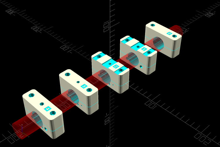
if (Layout == "Build") { |
|
n = len(FrameWidths); |
|
gap = 1.2; |
|
|
|
for (i=[0:n-1]) { |
|
j = i – ceil((n-1)/2); |
|
translate([-gap*Block.y/2,j*gap*Block.x,0]) |
|
rotate(90) |
|
HalfClamp(i,"Upper"); |
|
translate([gap*Block.y/2,j*gap*Block.x,0]) |
|
rotate([0,0,90]) |
|
HalfClamp(i,"Lower"); |
|
} |
|
} |