The Smell of Molten Projects in the Morning

Ed Nisley's Blog: Shop notes, electronics, firmware, machinery, 3D printing, laser cuttery, and curiosities. Contents: 100% human thinking, 0% AI slop.

Tag: Blinkies

Blinking & glowing LEDs

  • Satco PAR30 LED Spotlight Teardown

    Satco PAR30 LED Spotlight Teardown

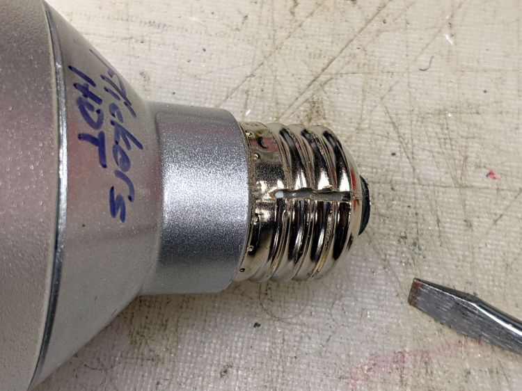
    One of those LED spotlights may have barely outlasted its worthless warranty, but not by much, and has been languishing on the back of the bench with “Flickers hot” scrawled on its side.

    The metal base didn’t respond to twisting, so I slit the threads with a cutoff wheel:

    Satco PAR30 - thread slit
    Satco PAR30 – thread slit

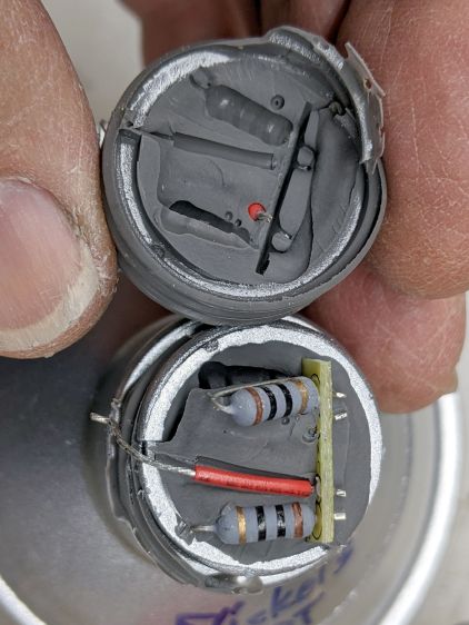
    Applying the screwdriver removed the base to reveal a silicone rubber casting:

    Satco PAR30 - thread silicone
    Satco PAR30 – thread silicone

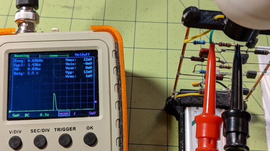
    The small wire emerging near the edge of the plastic case seems to be the neutral contact to the shell, with a poor enough joint to suggest it might have been why the lamp flickered when it got hot.

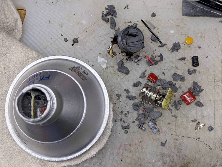
    Some brute force snapped the silicone off at the bottom of the plastic case and broke the two wires bringing AC to the PCB:

    Satco PAR30 - thread silicone base
    Satco PAR30 – thread silicone base

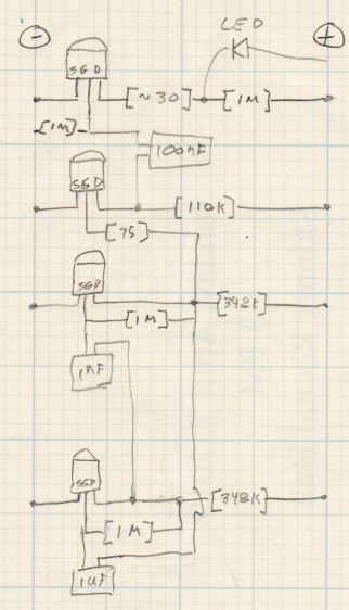
    Digging around inside produced a debris field of silicone crumbs, broken resistors, torn caps, and various other components, with zero progress toward removing the shell:

    Satco PAR30 - silicone extraction
    Satco PAR30 – silicone extraction

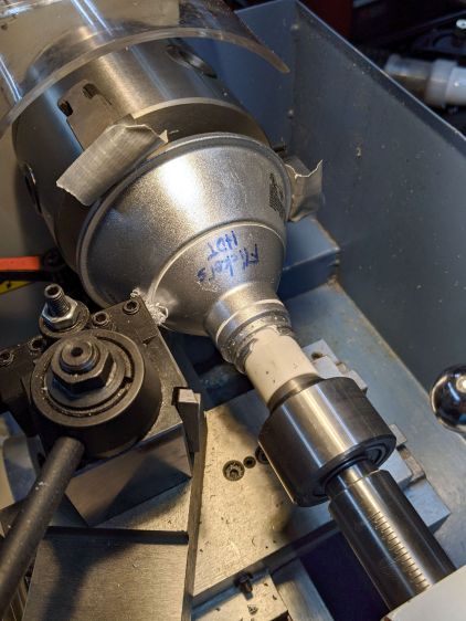
    A little lathe work converted a chunk of PVC pipe into a crude mandrel supporting the mangled case:

    Satco PAR30 - base cutting setup
    Satco PAR30 – base cutting setup

    A few millimeters of sissy cuts released a silicone O-ring sealing the shell against the reflector:

    Satco PAR30 - O-ring seal
    Satco PAR30 – O-ring seal

    Continuing the cuts eventually revealed the three screws holding the shell to the reflector and the two wires powering the LED:

    Satco PAR30 - reflector separated
    Satco PAR30 – reflector separated

    Chopping off the screws with a diagonal cutter freed the shell and revealed the top of the PCB:

    Satco PAR30 - electronics top
    Satco PAR30 – electronics top

    It really does have a surprising number of components!

    Those three screws connected the LED panel / heatsink to the shell through the back of the double-walled reflector. More brute force peeled the outer shell away and released the panel:

    Satco PAR30 - lens assembly
    Satco PAR30 – lens assembly

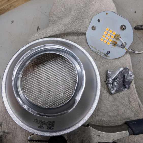
    Each of the 5050 packages contains a pair of white LEDs with 5.2 V forward drop for the pair, at the very low test current. They’re all in series, so you’re looking at well over 60 V total forward drop:

    Satco PAR30 - LED panel detail
    Satco PAR30 – LED panel detail

    Note that the wiring, which nobody will ever see, follows the electrical color code of white = common and gray = hot.

    Perhaps I should turn the lens into an interesting art object

  • Discrete LM3909: Blue LED

    Discrete LM3909: Blue LED

    Once again, the discrete LM3909 circuitry can blink a blue LED while running a pair of alkaline cells all the way down to about 1 V, with one cell ending at 0.2 V and the other at 0.8 V. They started out discharged to 1.2 V each during their useful life, then blinked for a month; it’s as good a use for dead cells as I can think of.

    With another pair of not-dead-yet cells providing 2.4 V, it started up again:

    Blue LM3909 2.4V alkaline - 042
    Blue LM3909 2.4V alkaline – 042

    That’s a frame from a short video taken in subdued light, just to show it really does work.

  • Discrete LM3909 Blue LED: Off at 1.0 V

    Discrete LM3909 Blue LED: Off at 1.0 V

    The blue LED inside the radome got fainter as the alkaline AA cells faded away, but remained visible in a dark room until the discrete LM3909 circuitry stopped oscillating with the battery at 1.0 V. One of the cells had flatlined, with the other supplying what little current was needed.

    The circuitry restarted with a pair of weak alkalines applying 2.4 V across the bus bars:

    LM3909 Blue - 2.4 V alkaline
    LM3909 Blue – 2.4 V alkaline

    The LED waveform shows it needs about 2 V:

    LM3909 Blue - 2.4 V alkaline
    LM3909 Blue – 2.4 V alkaline

    It’s barely visible in normal room light and strikingly bright at night.

  • Astable Multivibrator: Red RGB Piranha

    Astable Multivibrator: Red RGB Piranha

    A red LED has a sufficiently low forward voltage to run with a MOSFET astable multivibrator and a pair of run-down AA alkaline cells:

    Astable AA Alkaline - red
    Astable AA Alkaline – red

    The red LED is actually part of an RGB Piranha, just to see how it compares to an as-yet-unbuilt version with a single red LED in the same package.

    The LED drops 1.9 V of the 2.75 V from the mostly used-up AA cells:

    Astable Piranha Red - 2.75 alkaline - V LED
    Astable Piranha Red – 2.75 alkaline – V LED

    The original 33 Ω ballast resistor showed a peak current of 11 mA in a 30 ms pulse:

    Astable Piranha Red - 2.75 alkaline - V 33 ohm
    Astable Piranha Red – 2.75 alkaline – V 33 ohm

    Replacing it with a 12 Ω resistor boosts the current all the way to 12 mA:

    Astable Piranha Red - 2.75 alkaline - V 12 ohm
    Astable Piranha Red – 2.75 alkaline – V 12 ohm

    The 2N7000 gate sees a just bit more than 2 V, barely enough to get the poor thing conducting, which makes the ballast resistor mostly decorative. The MOSFET datasheet puts its 1 mA threshold somewhere between 0.8 and 3 V, so it could be worse.

    Keep in mind the DSO150’s 1 MΩ input impedance sat in parallel with the 1 MΩ gate pulldown resistor forming the RC differentiator when I measured the gate voltage; I’ll leave the simulation as an exercise for the interested reader. The blinks were noticeably dimmer and perhaps a bit shorter, although eyeballometric calibration is notoriously hard.

    The slightly revised schematic-layout doodle stacks the transistors along the negative bus bar:

    Astable wiring layout - stacked 2N7000
    Astable wiring layout – stacked 2N7000

    Flipping the bottom transistor over to snuggle the two timing caps next to each other would eliminate the long jumper wire and probably look better.

  • Astable Multivibrator: Amber LED

    Astable Multivibrator: Amber LED

    Adding an amber LED to the collection:

    Astable AA - Amber - overview
    Astable AA – Amber – overview

    Because a yellow / amber LED runs at a lower voltage than blue and green LEDs, it sits atop an astable multivibrator, rather than a discrete LM3909. The battery holder has a pair of carbon-zinc “Extra-Heavy Duty” AAA cells, so corrosion and leakage pose a foreseeable hazard.

    The voltage across the 100 Ω LED ballast indicates a 9 mA peak LED current, which is somewhat dim in ordinary room light:

    Astable AA - Amber - LED current 100 ohm
    Astable AA – Amber – LED current 100 ohm

    The corresponding LED voltage says the LED runs at 2.1 V for that much current:

    Astable AA - Amber - LED V
    Astable AA – Amber – LED V

    Something around 39 Ω should make it more visible.

  • Astable Multivibrator: Dressed-up LED Spider

    Astable Multivibrator: Dressed-up LED Spider

    Adding a bit of trim to the bottom of the LED spider makes it look better and helps keep the strut wires in place:

    Astable Multivibrator - Alkaline - Radome trim
    Astable Multivibrator – Alkaline – Radome trim

    It’s obviously impossible to build like that, so it’s split across the middle of the strut:

    Astable Multivibrator - Alkaline - Radome trim
    Astable Multivibrator – Alkaline – Radome trim

    Glue it together with black adhesive and a couple of clamps:

    LED Spider - glue clamping
    LED Spider – glue clamping

    The aluminum fixtures (jigs?) are epoxied around snippets of strut wire aligning the spider parts:

    LED Spider - gluing fixture
    LED Spider – gluing fixture

    Those grossly oversized holes came pre-drilled in an otherwise suitable aluminum rod from the Little Tray o’ Cutoffs. I faced off the ends, chopped the rod in two, recessed the new ends, and declared victory. Might need better ones at some point, but they’ll do for now.

    Next step: wire up an astable with a yellow LED to go with the green and blue boosted LEDs.

  • MOSFET Astable: NP-BX1 Rundown

    MOSFET Astable: NP-BX1 Rundown

    After eight months from a full charge, an old NP-BX1 lithium battery has come to this:

    Astable green - NP-BX1 - 2.31 V
    Astable green – NP-BX1 – 2.31 V

    The astable still ticks along at 1.4 seconds per blink, but the green LED barely lights up from a 2.1 V battery:

    Astable green - NP-BX1 - 12 mV 100 ohm
    Astable green – NP-BX1 – 12 mV 100 ohm

    A pulse of 12 mV across the 100 Ω resistor puts the LED current at a mere 120 µA: no wonder the poor thing wasn’t visible in ordinary room light.

    Another full charge restored its vigor for another couple of seasons.