-
Book Repair Tape vs. Serrated Cutter: Nope
An end-of-life roll of parchment paper contributed its serrated cutter bar as raw material for the Gridfinity Tape Dispenser:
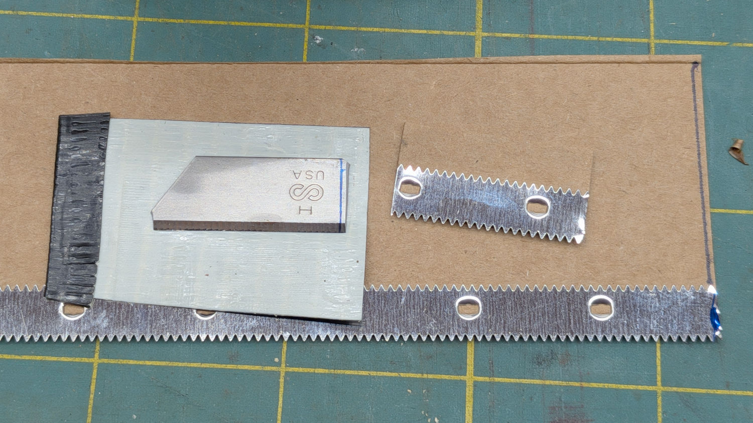
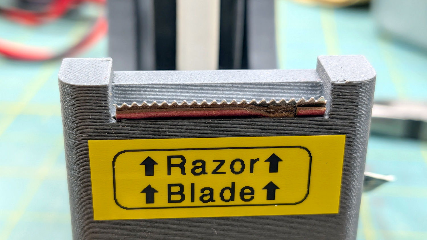
Gridfinity Tape Dispenser – razor vs serrated blades Those teeth look exactly like a tape cutter should look:
Gridfinity Tape Dispenser – serrated blade It turns out that book repair tape bounces right off the pointy-but-not-keen edges, to the extent the tape did not cut at all, no matter how hard I tugged at any angle. Perhaps filing one side to make the teeth thinner would improve the results; given the cutter’s provenance it seems like putting lipstick on a pig.
The original razor blade continues to work fine, so I dropped the serrated cutter into the hollow under the tape roll against future need.
Book repair tape is tough stuff!
-
Subscribe
Subscribed
Already have a WordPress.com account? Log in now.
