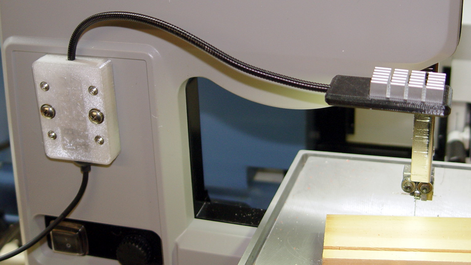
Those ugly square cable clips cried out for a cylindrical version:

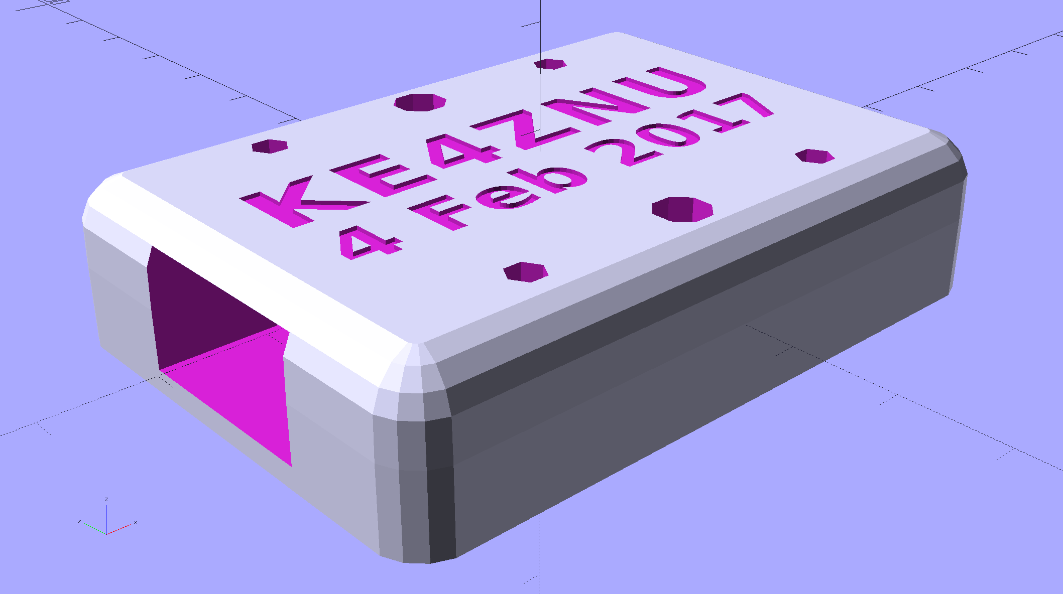
Which prompted a nice button:

Which suggested the square version needed some softening:
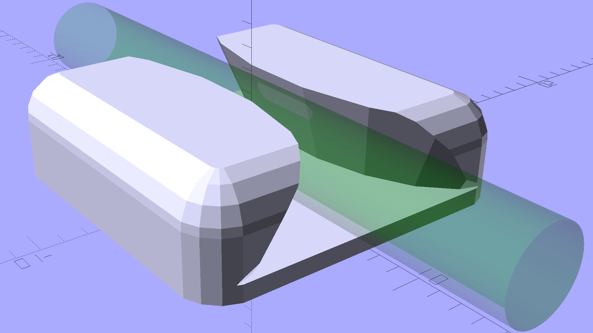
Apart from the base plate thickness, all the dimensions scale from the cable OD; I’ll be unsurprised to discover small cables don’t produce enough base area for good long-term foam tape adhesion. Maybe the base must have a minimum size or area?
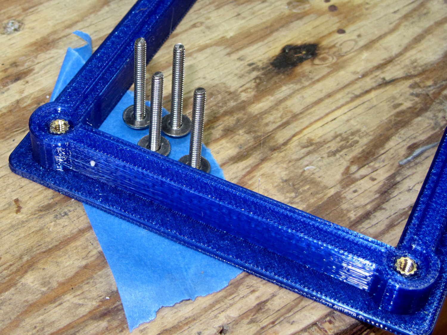
I won’t replace the ones already on the saw, but these will look better on the next project…
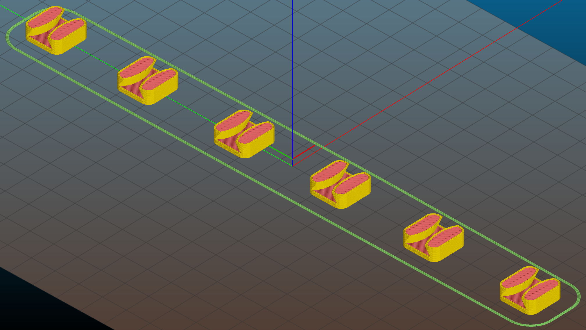
The OpenSCAD source code as a GitHub Gist:
This file contains hidden or bidirectional Unicode text that may be interpreted or compiled differently than what appears below. To review, open the file in an editor that reveals hidden Unicode characters.
Learn more about bidirectional Unicode characters
| // Cable Clips | |
| // Ed Nisley – KE4ZNU – October 2014 | |
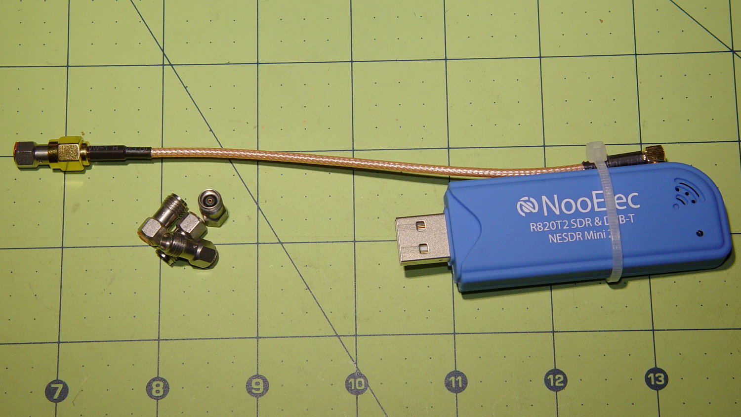
| // February 2017 – adapted for USB cables | |
| Layout = "Show"; // Show Build | |
| Style = "Button"; // Square Round Button | |
| //- Extrusion parameters must match reality! | |
| ThreadThick = 0.25; | |
| ThreadWidth = 0.40; | |
| HoleWindage = 0.2; // extra clearance | |
| Protrusion = 0.1; // make holes end cleanly | |
| function IntegerMultiple(Size,Unit) = Unit * ceil(Size / Unit); | |
| //———————- | |
| // Dimensions | |
| CableOD = 3.8; // cable jacket | |
| Base = [4*CableOD,4*CableOD,3*ThreadThick]; // overall base and slab thickness | |
| CornerRadius = CableOD/2; // radius of square corners | |
| CornerSides = 4*4; // total sides on square corner cylinders | |
| NumSides = 6*3; // total sides for cylindrical base | |
| //– Oval clip with central passage | |
| module CableClip() { | |
| intersection() { | |
| if (Style == "Square") | |
| hull() | |
| for (i=[-1,1], j=[-1,1]) | |
| translate([i*(Base[0]/2 – CornerRadius),j*(Base[1]/2 – CornerRadius),0]) | |
| rotate(180/CornerSides) { | |
| cylinder(r=CornerRadius,h=Base[2] + CableOD/2,$fn=CornerSides,center=false); | |
| translate([0,0,Base[2] + CableOD/2]) | |
| sphere(d=CableOD,$fn=CornerSides); | |
| } | |
| else if (Style == "Round") | |
| cylinder(d=Base[0],h=Base[2] + 1.00*CableOD,$fn=NumSides); | |
| else if (Style == "Button") | |
| resize(Base + [0,0,2*(Base[2] + CableOD)]) | |
| sphere(d=Base[0],$fn=NumSides); | |
| union() { | |
| translate([0,0,Base[2]/2]) // base defines slab thickness | |
| cube(Base,center=true); | |
| for (j=[-1,1]) // retaining ovals | |
| translate([0,j*(Base[1]/2 – 0.125*(Base[1] – CableOD)/2),(Base[2] – Protrusion)]) | |
| resize([Base[0]/0.75,0,0]) | |
| cylinder(d1=0.75*(Base[1]-CableOD), | |
| d2=(Base[1]-CableOD)/cos(0*180/NumSides), | |
| h=(CableOD + Protrusion), | |
| center=false,$fn=NumSides); | |
| } | |
| } | |
| if (Layout == "Show") | |
| color("Green",0.2) | |
| translate([0,0,Base[2] + CableOD/2]) | |
| rotate([0,90,0]) | |
| cylinder(d=CableOD,h=2*Base[0],center=true,$fn=48); | |
| } | |
| //———————- | |
| // Build it | |
| CableClip(); | |