My attempt to use a HP 7475A plotter as a vinyl cutter failed due to its 19 g pen load limit:

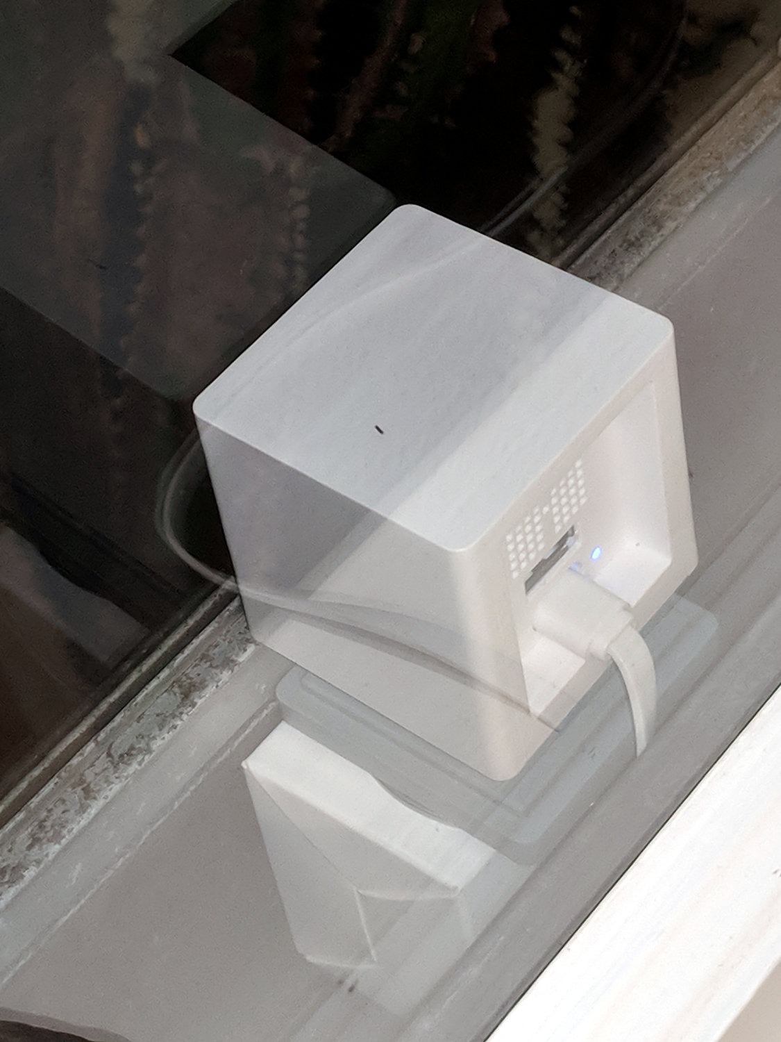
The MPCNC, however, can apply plenty of downforce, so I tinkered up a quick-and-dirty adapter to put the drag knife “pen” body into the MPCNC’s standard DW660 router holder:
That’s using the DW660 adapter upside-down to get the business end of the knife closer to the platform. The solid model descends from the linear-bearing Sakura pen holder by ruthless pruning.
It didn’t work well at all, because you really need a spring for some vertical compliance and control over the downforce pressure.
Back to the Comfy Chair:

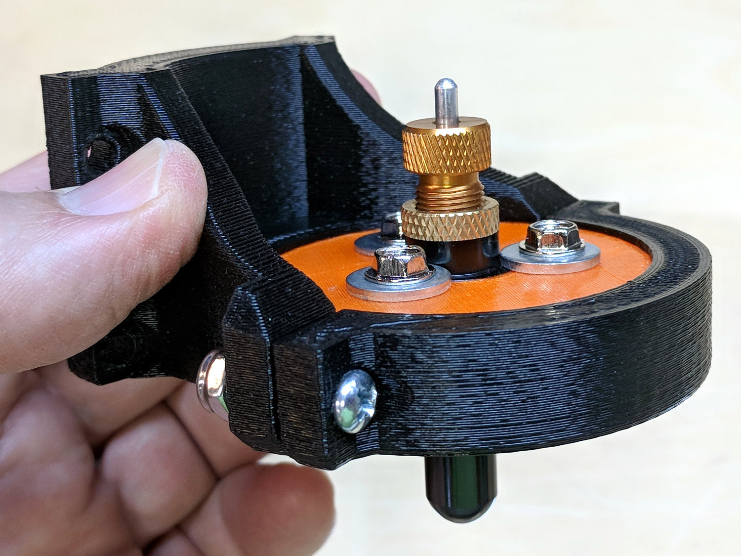
A trio of the lightest springs from a 200 piece assortment (in the front left compartment) pushes the upper plate downward against the drag knife’s flange:

There’s a bit more going on than may be obvious at first glance.
The screws slide in brass tubing press-fit into the upper plate, because otherwise their threads hang up on the usual 3D printed layers inside the (drilled-out) holes. Smaller free-floating brass tubing snippets inside the springs keep them away from the screw threads; the gap between the top of the tubing and the screw head limits the vertical compliance to 3 mm. The screws thread into brass inserts epoxied into the bottom disk, with a dab of low-strength Loctite for stay-put adjustment.
I bored the orange PETG disk to a nice slip fit around the knife body:
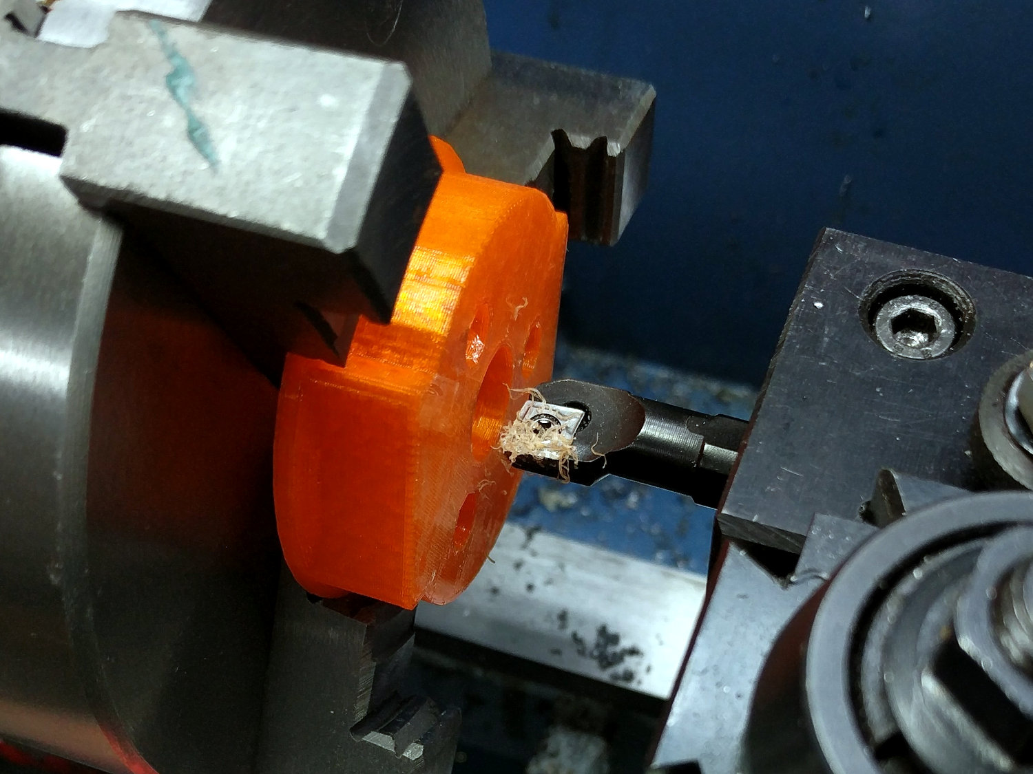
The upper plate also required fitting:

A few iterations produced reasonably smooth motion over a few millimeters, but it’s definitely not a low-friction / low-stiction drag knife holder. It ought to be good for some proof-of-concept vinyl cutting, though.
The OpenSCAD source code as a GitHub Gist:
| // Drag Knife Holder for DW660 Mount | |
| // Ed Nisley KE4ZNU – 2018-09-26 | |
| Layout = "Show"; // Build, Show, Puck, Mount, Plate | |
| /* [Extrusion] */ | |
| ThreadThick = 0.25; // [0.20, 0.25] | |
| ThreadWidth = 0.40; // [0.40] | |
| /* [Hidden] */ | |
| Protrusion = 0.1; // [0.01, 0.1] | |
| HoleWindage = 0.2; | |
| inch = 25.4; | |
| function IntegerMultiple(Size,Unit) = Unit * ceil(Size / Unit); | |
| ID = 0; | |
| OD = 1; | |
| LENGTH = 2; | |
| //- Adjust hole diameter to make the size come out right | |
| module PolyCyl(Dia,Height,ForceSides=0) { // based on nophead's polyholes | |
| Sides = (ForceSides != 0) ? ForceSides : (ceil(Dia) + 2); | |
| FixDia = Dia / cos(180/Sides); | |
| cylinder(r=(FixDia + HoleWindage)/2,h=Height,$fn=Sides); | |
| } | |
| //- Dimensions | |
| KnifeBody = [12.0,16.0,2.0]; // body flange — resembles HP plotter pen | |
| WallThick = 3.0; // minimum thickness / width | |
| Screw = [4.0,8.5,8.0]; // holding it all together, OD = washer | |
| Insert = [4.0,6.0,10.0]; // brass insert | |
| Plate = [KnifeBody[ID],KnifeBody[OD] + 3*Screw[OD],4.0]; // spring reaction plate | |
| PlateGuide = [4.0,4.8,Plate[LENGTH]]; // … guide tubes | |
| NumScrews = 3; | |
| ScrewBCD = 2*(KnifeBody[OD]/2 + Screw[OD]/2 + 0.5); | |
| NumSides = 9*4; // cylinder facets (multiple of 3 for lathe trimming) | |
| // Basic shape of DW660 snout fitting into the holder | |
| // Lip goes upward to lock into MPCNC mount | |
| Snout = [44.6,50.0,9.6]; // LENGTH = ID height | |
| Lip = 4.0; // height of lip at end of snout | |
| PuckOAL = Snout[LENGTH] + Lip; // total height | |
| Key = [Snout[ID],25.7,PuckOAL]; // rectangular key | |
| module DW660Puck() { | |
| translate([0,0,PuckOAL]) | |
| rotate([180,0,0]) { | |
| cylinder(d=Snout[OD],h=Lip/2,$fn=NumSides); | |
| translate([0,0,Lip/2]) | |
| cylinder(d1=Snout[OD],d2=Snout[ID],h=Lip/2,$fn=NumSides); | |
| cylinder(d=Snout[ID],h=PuckOAL,$fn=NumSides); | |
| intersection() { | |
| translate([0,0,0*Lip + Key.z/2]) | |
| cube(Key,center=true); | |
| cylinder(d=Snout[OD],h=Lip + Key.z,$fn=NumSides); | |
| } | |
| } | |
| } | |
| module MountBase() { | |
| difference() { | |
| DW660Puck(); | |
| translate([0,0,-Protrusion]) // knife holder body | |
| PolyCyl(KnifeBody[ID],2*PuckOAL,NumSides); | |
| translate([0,0,PuckOAL – KnifeBody[LENGTH]/2]) // … half of flange, loose fit | |
| PolyCyl(KnifeBody[OD] + 2*HoleWindage,KnifeBody[LENGTH],NumSides); | |
| for (i=[0:NumScrews – 1]) // clamp screws | |
| rotate(i*360/NumScrews) | |
| translate([ScrewBCD/2,0,-Protrusion]) | |
| rotate(180/8) | |
| PolyCyl(Insert[OD],2*PuckOAL,8); | |
| } | |
| } | |
| module SpringPlate() { | |
| difference() { | |
| cylinder(d=Plate[OD],h=Plate[LENGTH],$fn=NumSides); | |
| translate([0,0,-Protrusion]) // knife holder body | |
| PolyCyl(KnifeBody[ID],2*PuckOAL,NumSides); | |
| translate([0,0,Plate[LENGTH] – KnifeBody[LENGTH]/2]) // … half of flange, snug fit | |
| PolyCyl(KnifeBody[OD],KnifeBody[LENGTH],NumSides); | |
| for (i=[0:NumScrews – 1]) // clamp screws | |
| rotate(i*360/NumScrews) | |
| translate([ScrewBCD/2,0,-Protrusion]) | |
| rotate(180/8) | |
| PolyCyl(PlateGuide[OD],2*PuckOAL,8); | |
| } | |
| } | |
| //—– | |
| // Build it | |
| if (Layout == "Puck") | |
| DW660Puck(); | |
| if (Layout == "Plate") | |
| SpringPlate(); | |
| if (Layout == "Mount") | |
| MountBase(); | |
| if (Layout == "Show") { | |
| MountBase(); | |
| translate([0,0,2*PuckOAL]) | |
| rotate([180,0,0]) | |
| SpringPlate(); | |
| } | |
| if (Layout == "Build") { | |
| translate([0,Snout[OD]/2,0]) | |
| MountBase(); | |
| translate([0,-Snout[OD]/2,0]) | |
| SpringPlate(); | |
| } |