Ed Nisley's Blog: Shop notes, electronics, firmware, machinery, 3D printing, laser cuttery, and curiosities. Contents: 100% human thinking, 0% AI slop.
Category: Software
General-purpose computers doing something specific
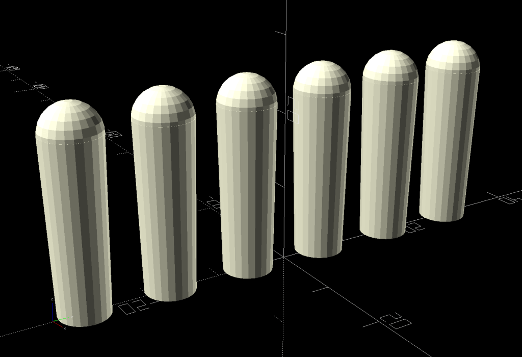
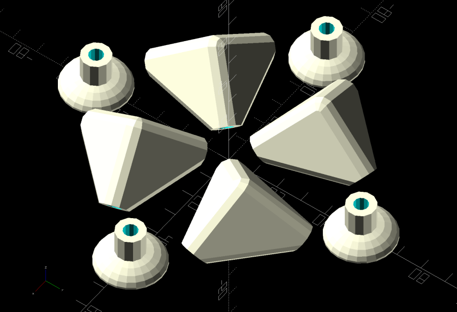
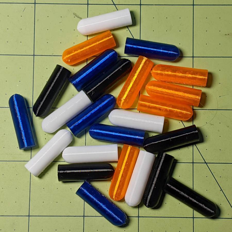
As is all too common with 3D printed replacement parts done remotely, the first Shuttles game pegs didn’t quite fit into the game board’s holes. Fortunately, living in the future means rapid prototyping and quick turnaround:
Shuttles Game pegs – tapered – solid model
They’re slightly smaller, tapered toward the bottom, and take slightly less time to print.
The OpenSCAD code in the GitHub Gist now has has the tweaks.
Given a collection of music files in various subdirectories, find all the mp3 files that aren’t in the target directory and copy them. The only catch: don’t use rsync, because the target directory is on a Google Pixel phone filesystem which doesn’t support various attributes required by rsync.
The trick is remembering the second execdir operation in find happens only if the first succeeds, so the cp runs when the target file doesn’t exist.
All the backslash escaping gets tedious, but it’s the least awful way to get the job done when the directories contain blanks, which is true for the default directory structure inside the Pixel.
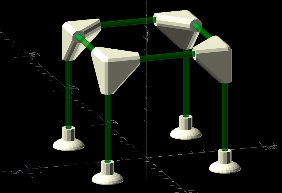
Plant seedlings started in pots require some hardening off time outdoors before being transplanted. Veggie seedlings also require protection from critters regarding them as a buffet, so Mary covers them with a sheet of floating row cover, which must be both suspended over the plants to give them growing room and tucked under the tray to keep the bugs out. She asked for a frame to simplify the process:
Mesh Shelter Frame – assembled
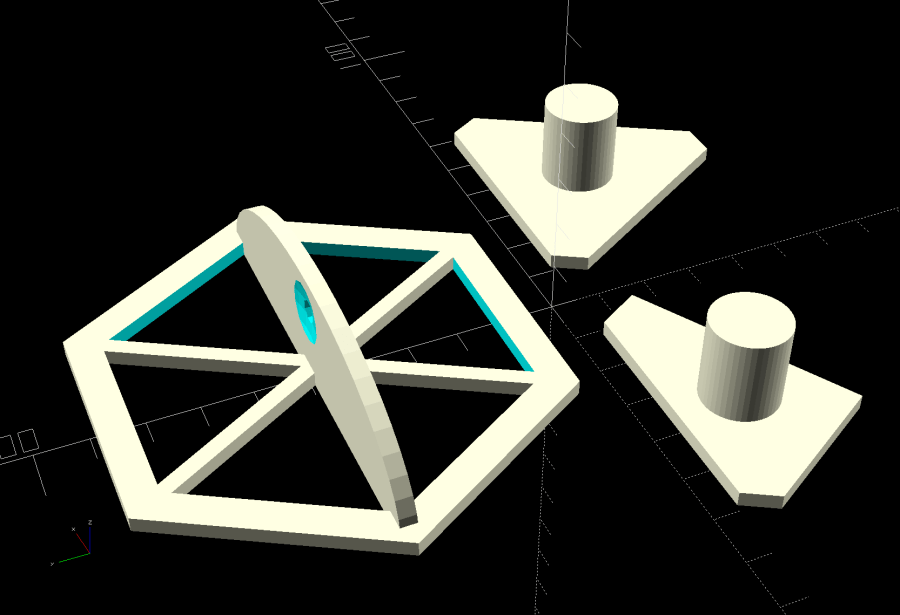
The solid model shows the structure with no regard for proportion:
Mesh Shelter Frame – show view
The 5 mm fiberglass rods come from our decommissioned six-passenger umbrella, cut to length in the Tiny Lathe™ by applying a Swiss Pattern knife file around the perimeter, over the ShopVac’s snout to catch the glass dust. I started with a pull saw (also over the vacuum) during the weekly Squidwrench v-meeting, whereupon Amber recommended either a Dremel slitting wheel or a file, so I mashed everything together and it worked wonderfully well, without producing any errant glass-fiber shards to impale my fingers.
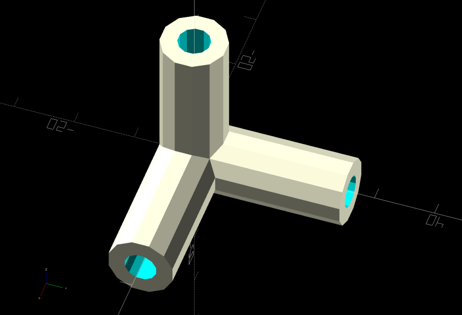
The corners consist of three tubes stuck together at the origin:
Mesh Shelter Frame – non-hulled corner model
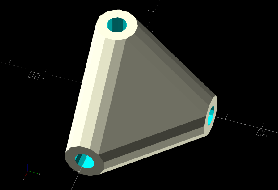
Shrink-wrapping them with a hull() adds plenty of strength where it’s needed:
Mesh Shelter Frame – hulled corner model
I decided putting the belly side (facing you in the picture) downward on the platform and the peak upward would distribute the distortion equally among the tubes and produce a nicely rounded outer surface for the mesh fabric:
Mesh Shelter Frame – build layout
Which led to some Wikipedia trawling to disturb the silt over my long-buried analytic geometry, plus some calculator work to help recall the process; back in the day I would have used a slipstick, but I was unwilling to go there. Although I could special-case this particular layout, the general method uses Euler’s Rotation Theorem, simplified because I need only one rotation.
Should you need concatenated rotations, you probably need quaternions, but, at this point, I don’t even remember forgetting quaternions.
Anyhow, the Euler rotation axis is the cross product of the [1,1,1] vector aimed through the middle of the corner’s belly with the [0,0,-1] target vector pointing downward toward the platform. The rotation amount is the acos() of the dot product of those two vectors divided by the product of their norms. With vector and angle in hand, dropping them into OpenSCAD’s rotate() transformation does exactly what’s needed:
rotate(acos((BaseVector*Nadir)/(norm(BaseVector)*norm(Nadir))),
       v=cross(BaseVector,Nadir))   // aim belly side downward
  Corner();
Dang, I was so happy when that worked!
Because the corner model rotates around the origin where all three tube centerlines meet, the result puts the belly below the platform, pointed downward. The next step applies a translation to haul the belly upward:
translate([ArmOAL,0,    // raise base to just below platform level
           ArmOC/sqrt(3) + (ArmRadius/cos(180/SocketSides))*cos(atan(sqrt(3)/2)) + Finagle])
This happens in a loop positioning the four corners for printing, so the first ArmOAL as the X axis parameter translates the shape far enough to let four of them coexist around the origin, as shown above.
The mess in the Z axis parameter has three terms:
Raise the centerline of the ends of the tubes to Z=0
Raise the rim of the tube to Z=0
Add a wee bit to make the answer come out right
The 0.18 mm Finagle constant fixes things having to do with the hull() applied to miscellaneous leftover angled-circles-as-polygons approximations and leaves just a skin below the platform to be sheared off by a huge cube below Z=0, matching the corner bellies with the bottoms of the feet.
Because the corners have awful overhangs, the results look a bit raggedy:
Mesh Shelter Frame – corner underside
That’s after knocking off the high spots with a grubby sanding sponge and making a trial fit. They look somewhat less grotendous in person.
If we need another iteration, I’ll think hard about eliminating the overhangs by splitting the corner parallel to the belly, flipping the belly upward, and joining the pieces with a screw. What we have seems serviceable, though.
This file contains hidden or bidirectional Unicode text that may be interpreted or compiled differently than what appears below. To review, open the file in an editor that reveals hidden Unicode characters.
Learn more about bidirectional Unicode characters
Having just emptied a propane tank while making bacon, I couldn’t find any of the wrench adapters I made to remove the QD adapter from the tank’s POL fitting. With memory of the broken garden valve wrench still fresh, I tweaked the solid model to include a trio of 1 mm music wire reinforcements:
Propane QD Adapter Tool – reinforced – Slic3r
Holes that small require clearing with a 1 mm drill, after which ramming the wires in place poses no problem:
Reinforced QD Adapter Tool – inserting wire
Except for the one that got away:
Reinforced QD Adapter Tool – errant wire
The music wire came from a coil and each snippet required gentle straightening; perhaps that one wasn’t sufficiently bar-straight.
Anyhow, I printed two tools for that very reason:
Reinforced QD Adapter Tool – side view
They’re now where I can’t miss ’em the next time I need them, although that’s not where the previous ones reside.
This file contains hidden or bidirectional Unicode text that may be interpreted or compiled differently than what appears below. To review, open the file in an editor that reveals hidden Unicode characters.
Learn more about bidirectional Unicode characters
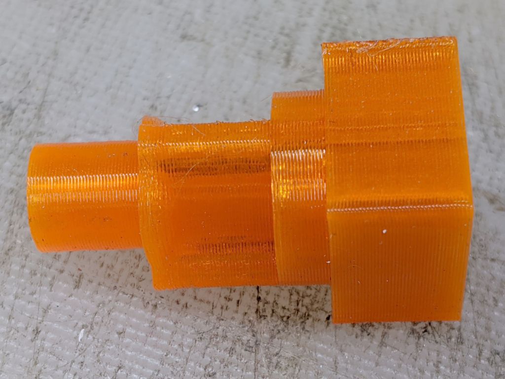
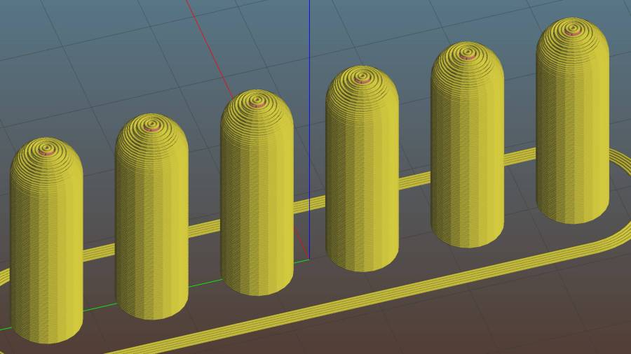
For reasons not relevant here, I made replacement pegs for the Shuttles board game:
Shuttles Game – solid model – Slic3r
Not the most challenging solid model I’ve ever conjured from the vasty digital deep, but 3D printing is really good for stuff like this.
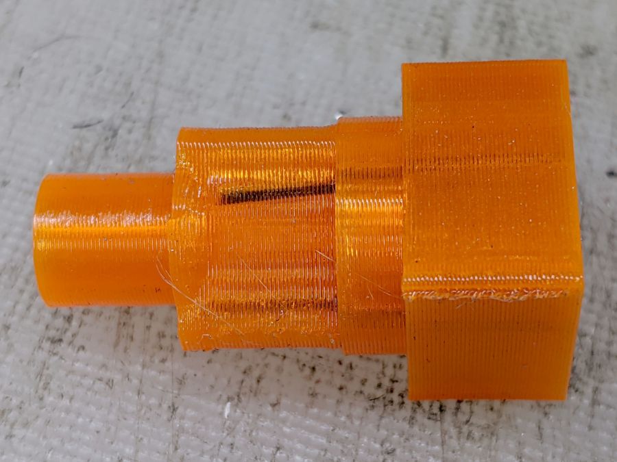
The OEM pegs have a hollow center, most likely to simplify stripping them from the injection mold, which I dutifully duplicated:
Shuttles Game pegs – hollow – solid model
It turns out the additional perimeter length inside the pegs requires 50% more printing time, far offsetting the reduced 10% infill. Given that each solid set takes just under an hour, I decided to lose half an hour of verisimilitude.
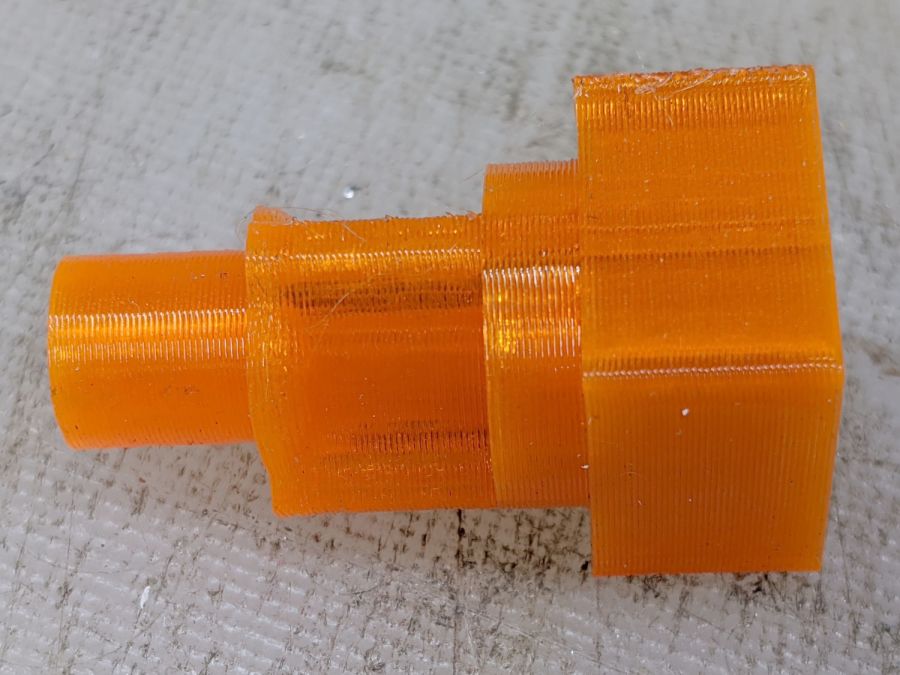
I plunked a nice round cap atop the OEM peg’s flat end, but stopped short of printing & installing a round plug for the butt end.
While the 3D printer’s hot, ya may as well make a bunch:
Update: They’re a bit too large, so the Gist now produces tapered pegs.
This file contains hidden or bidirectional Unicode text that may be interpreted or compiled differently than what appears below. To review, open the file in an editor that reveals hidden Unicode characters.
Learn more about bidirectional Unicode characters
Mary took on the task of finishing a hexagonal quilt from pieced strips, only to discover she’ll need several more strips and the myriad triangles required to turn hexagons into strips. The as-built strips do not match any of the standard pattern sizes, which meant ordinary templates were unavailing. I offered to build a template matching the (average) as-built hexagons, plus a triangle template based on those dimensions.
Quilters measure hexes based on their finished side length, so a “1 inch hex” has sides measuring 1 inch, with the seam allowance extending ¼ inch beyond the sides. It’s difficult to measure finished sides with sufficient accuracy, so we averaged the side-to-side distance across several hexes.
Some thrashing around produced a quick-and-dirty check piece that matched (most of) the stack of un-sewn hexes:
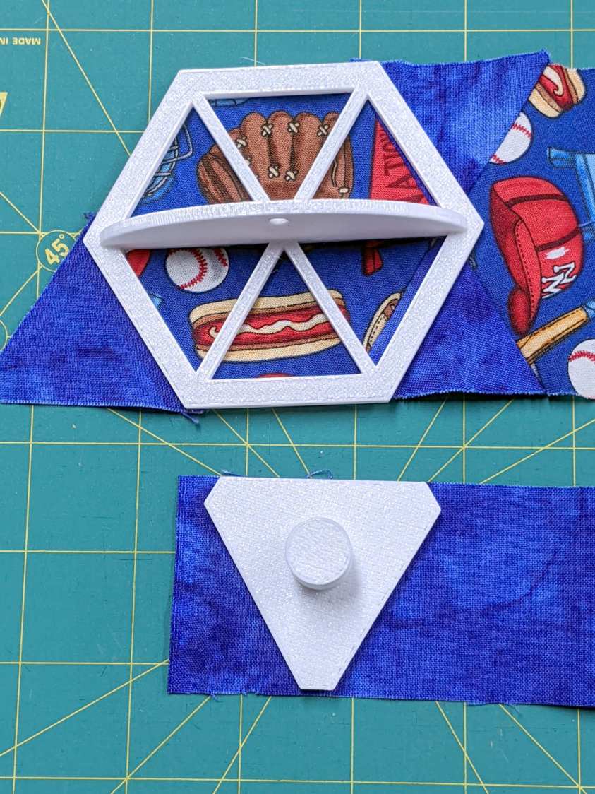
Quilting Hexagon Cutting Template
That one came from a knockoff of the circle template, after some cleanup & tweakage, but failed user testing for not withstanding the side force from the rotary cutter blade. The inside and outside dimensions were correct, however, so I could proceed with some confidence I understood the geometry.
Both the pattern width (the side-to-side distance across the inside of the hex) and the seam allowance appearing in the Customizer appear in inches, because that’s how things get measured outside the Basement Laboratory & Fabrication Facility:
You feed in one side-to-side measurement and all other hex dimensions get calculated from that number; quilters default to a ¼ inch seam allowance. Remember, standard quilt hexes are measured by their side length, so just buy some standard templates.
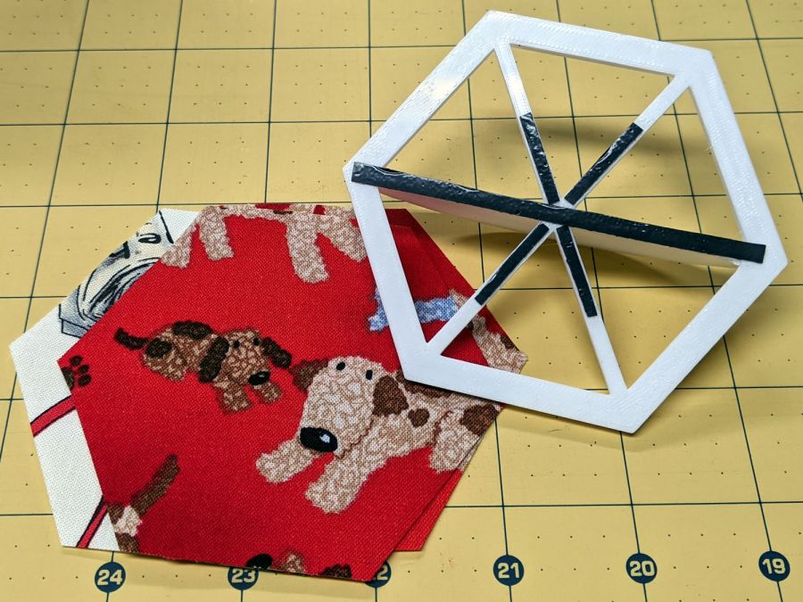
Both templates have non-skid strips to keep the fabric in place while cutting:
Hex Quilting Template – grip strips
I should have embossed the size on each template, but this feels like a one-off project and YAGNI. Of course, that’s how I felt about the circle templates, so maybe next time I’ll get it right.
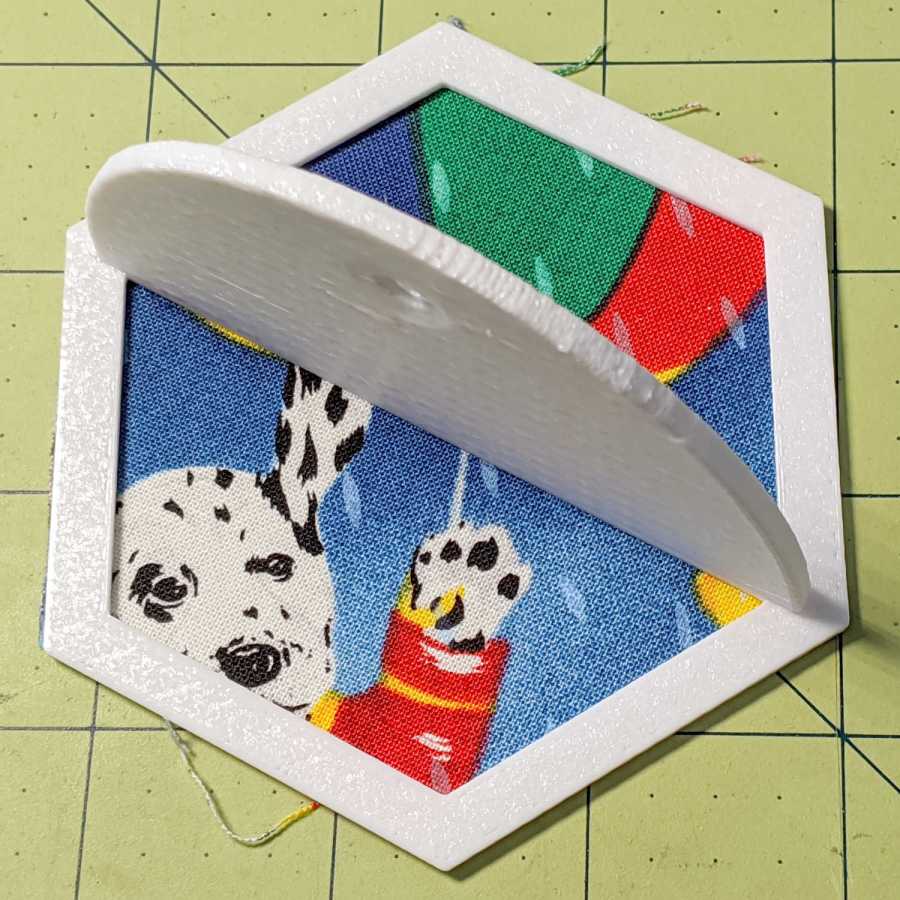
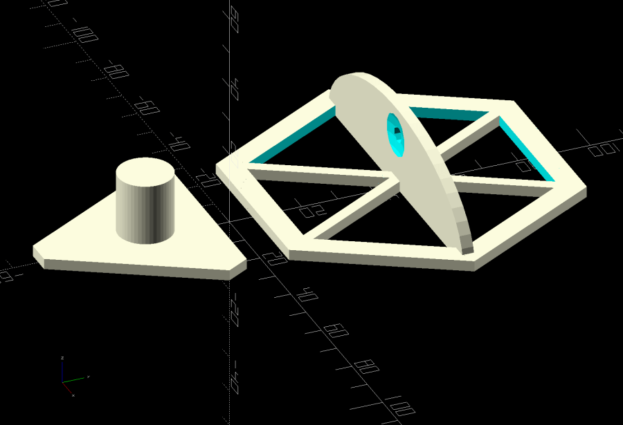
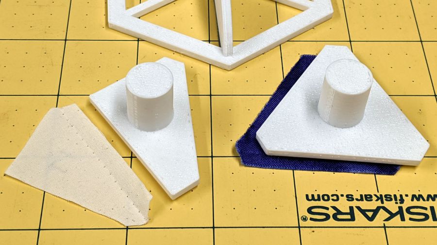
As it turned out, Mary realized she needed a template for the two half-triangles at the end of each row:
Quilting Hex Template – half-triangle
It’s half of the finished size of the equilateral triangle on the right, with seam allowance added all around. The test scrap of fabric on the left shows the stitching along the hypotenuse of the half-triangle, where it joins to the end-of-row hexagon. Ideally, you need two half-triangle templates, but Mary says it’s easier to cut the fabric from the back side than to keep track of two templates.
This file contains hidden or bidirectional Unicode text that may be interpreted or compiled differently than what appears below. To review, open the file in an editor that reveals hidden Unicode characters.
Learn more about bidirectional Unicode characters
I’m not entirely clear what’s being audited in the Manjaro Linux boxes I’ve recently set up, nor what the difference between res=success and res=failed might mean for the x11vnc unit:
That’s the better part of two seconds in the life of the box and, later on, the pace picks up. Casual searching suggests nobody else knows what’s going on, either, apart from the fact than that it obviously has something to do with systemd and, thus, is just the way things are these days.
Add audit=off to the default kernel command-line parameters by editing /etc/default/grub thusly: