Ed Nisley's Blog: Shop notes, electronics, firmware, machinery, 3D printing, laser cuttery, and curiosities. Contents: 100% human thinking, 0% AI slop.
Category: Software
General-purpose computers doing something specific
Posterizing the colors to represent a few shades in my Little Box o’ Veneers simplified the problem:
Tree frog – posterized
Applying LightBurn’s Trace tool to the various shades produced vector outlines, which I then collected together based on the veneer they should come from:
Tree Frog vector patterns
Which seemed similar to my hand-drawn doodles on a larger image:
Tree frog – sketch vs chipboard
Before committing to actual veneers, though, I cut the shapes from spraypainted chipboard on a small scale, which showed why this wasn’t going to work:
Tree Frog – auto-trace chipboard
It’s facing the other way because I cut the chipboard from the back side, so as to keep the colors reasonably clean and bright.
Contrary to what I initially thought, the automagic tracing routine generates different nodes along a boundary between two colors depending on which side is selected by the color range. Because the nodes (and control points) don’t match exactly, adjacent pieces will have different border shapes and won’t quite match up. The missing pieces at the frog’s rump simply did not fit after the other parts soaked up all the tolerances in between.
So (I think) a better way to do this requires carefully hand-tracing the borders, then using the same path (all the nodes) for adjoining pieces. This mean duplicating the borders for each of the pieces: tedious bookkeeping and layer manipulation.
It seems that Manjaro’s 5.0.0-1 version of the yubikey-managercrashes due to inscrutable errors, with the effect of not letting me use it to sign in at all the sites I’d set up to use TOTP authentication.
sudo pacman -U /tmp/yubikey-manager-4.0.9-1-any.pkg.tar.zst

loading packages...
warning: downgrading package yubikey-manager (5.0.0-1 => 4.0.9-1)
resolving dependencies...
looking for conflicting packages...

Packages (1) yubikey-manager-4.0.9-1

Total Installed Size:   1.11 MiB
Net Upgrade Size:      -0.13 MiB

:: Proceed with installation? [Y/n] Y
<<< snippage >>>
Whereupon It Just Worked™ again.
I expect someone more experienced than I will have long since filed a bug report / sent a pull request / whatever, because I have little idea how to do any of that. The next upgrade should work just fine.
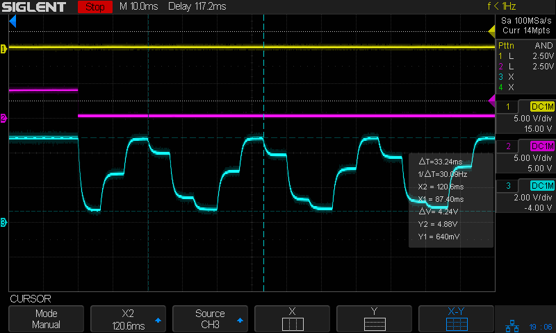
Then if you tell LightBurn to engrave the pattern with a line-to-line (vertical) spacing of 127 dpi = 5 pixel/mm, it will sample every other pixel in each row, producing a rather peculiar sine-ish wave:
Tube Current – analog bandwidth – 10 sine – 25mm-s – beam off – 127dpi
You must engrave at 254 dpi = 10 pixel/mm in order to get all the pixels in the output stream:
Tube Current – analog bandwidth – 10 sine – 25mm-s – beam off – 254dpi
That still looks gnarly, but it’s more along the lines of what the coarse 10 samples / cycle pattern calls for.
The risetime for each of those steps is on the order of 2 ms, so the controller’s analog output bandwidth isn’t much better than 150-ish Hz.
Close examination of the bar pattern shows the end of the first cycle really does hit exactly 0% intensity where the controller raises L-ON (magenta trace) to force the output current to zero. The other minima remain a few percent above zero and cannot be squashed flat.
Today I Learned: LightBurn enforces square pixels at the line spacing distance for grayscale engraving.
I think this means you must resize / resample the grayscale image to match the engraving line spacing, because LightBurn could take the nearest adjacent pixel or average two adjacent pixels if its horizontal sampling doesn’t match the image resolution.
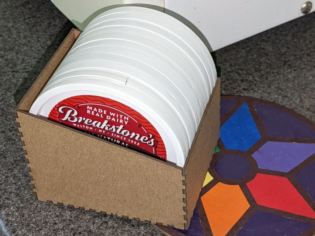
Mary reuses empty sour cream / ricotta cheese / cottage cheese to freeze / store garden produce, which results in a need to store their lids:
Lid box – filled
It’s made from 1.5 mm chipboard, which seems both sturdy enough for the purpose and sufficiently stylin’ for life in a middle drawer.
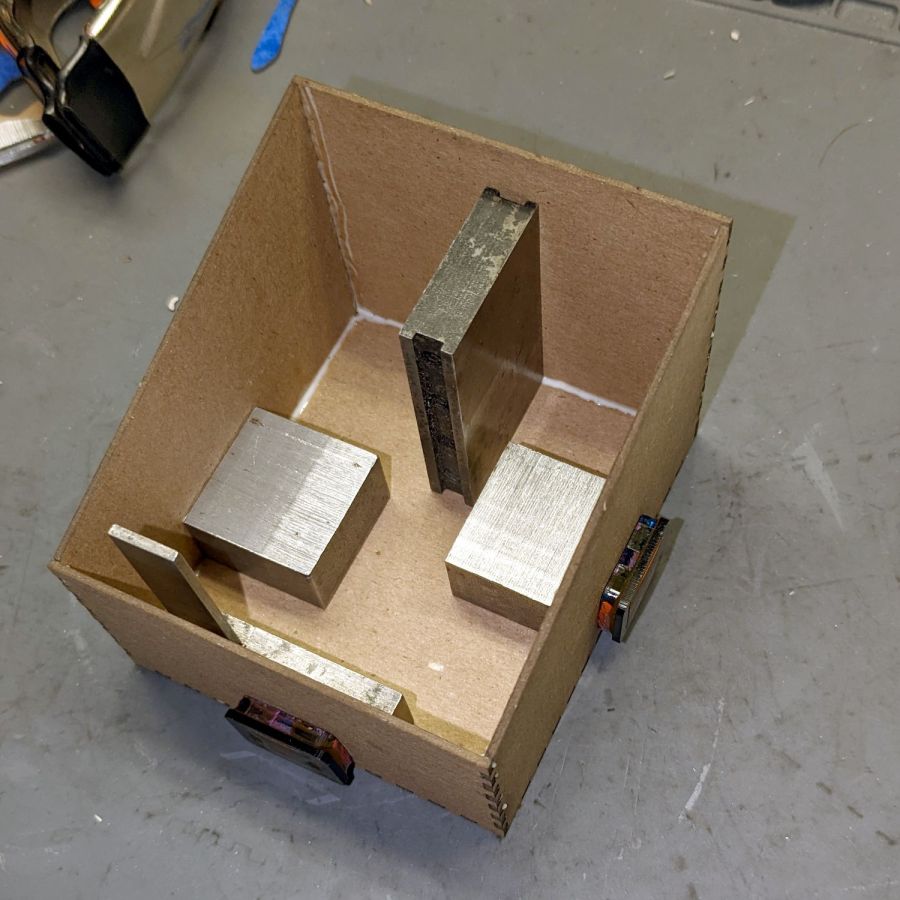
A bead of Elmer’s yellow wood glue along the tops of meshing fingers (which then hits the bottom of the opposing slots) holds the joints together, with a quartet of steel blocks + magnets ensuring perpendicularity during curing:
Lid box – gluing
The glue cures to a transparent skin, so it doesn’t look nearly as awful as you might think. Besides, being inside with lids all over, nobody will ever see the overage. Right?
The box pattern comes from the wonderful boxes.py as a magic URL:
I set up my pobox.com account set up with two-factor authentication through my Yubikey, so logging in requires my user ID, password, and a Time-based One-time Password generated through the Yubikey Authenticator program. A few weeks ago, pobox occasionally rejected the TOTP and it eventually became a hard failure. Oddly, other sites I’ve set up with TOTP 2FA continued to work fine.
My initial trouble report:
The last couple of times I’ve tried to sign in, the usual TOTP copy-n-paste from my Yubikey authenticator has failed.
Up to that point, it worked flawlessly.
Manually typing the TOTP also fails.
I have reset my (complex!) password to no avail; I use Firefox’s password manager to fill it in.
I do have a set of lockout codes, but they’re a solution to a different problem.
Given the constant updates to Firefox (102.0.3), it’s almost certain the hole is in my end of the boat. I have disabled all the usual ad blocking for pobox.com, although there may be other domains I’ve overlooked.
Other than that, my email seems to be working just fine …
Any suggestions on how to proceed? (Obviously, I’m not going to be able to sign on to look at the ticket.)
Thanks …
This is the fastest I’ve ever reached Tier 2:
We’re happy to help you with this. I’ve escalated your ticket to our Tier 2 agents, as they are best suited to assist with this issue.
There is nothing like a good new problem to take your mind off all your old problems:
I’ve had a chat with our Tier 2 agents about this and they’ve suggested I escalate it to our developers to have a look at.
Somewhat later:
I am afraid to say that our developers were unable to find any clear reason as to why your Yubikey failed.
Yubikey devices verify by connecting with Yubikey’s server, and it is possible that this connection failed.
Can you please try using the Yubikey again to see if the issue is still occurring?
If it’s still failing, can you please try adding a new Yubikey device to see if it works?
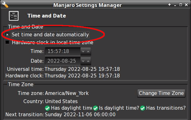
Of course, the problem didn’t magically Go Away, but I did more experimentation and figured out where the hole was in my end of the boat:
Ah-HA! It’s a PEBKAC error!
For unknown reasons, this PC was not set for automatic NTP time updates(*). Its time had drifted (presumably since I installed it back in June 2021) and was now 58 seconds behind real time, exceeding pobox’s tolerance.
Other websites apparently allow a few more seconds of slop before disallowing a TOTP, so I had not yet run afoul of their limit.
Some lesser-used sites threw me out, however, but I had not looked beyond the most common sites.
The default TOTP interval is 30 seconds, so perhaps pobox allows only ±1 interval and the other sites allow ±2? Frankly, I think pobox has it right: everybody else prioritizes customer sat over security.
Got the clock set correctly and, gosh, TOTP works fine.
Mark it solved, but definitely add “Soooo, is your PC’s clock set for automatic updates?” to the debugging protocol.
Thanks …
(*) I’ve installed all of the boxen here and would not ever have picked “Yeah, sure, I want to dink with the clock.”
How you make sure time synchronization is enabled goes like this:
$ systemctl status systemd-timesyncd.service
● systemd-timesyncd.service - Network Time Synchronization
     Loaded: loaded (/usr/lib/systemd/system/systemd-timesyncd.service; enabled; preset: enabled)
     Active: active (running) since Thu 2022-08-25 06:49:31 EDT; 10h ago
       Docs: man:systemd-timesyncd.service(8)
   Main PID: 355 (systemd-timesyn)
     Status: "Contacted time server 23.157.160.168:123 (2.manjaro.pool.ntp.org)."
      Tasks: 2 (limit: 19063)
     Memory: 2.2M
        CPU: 188ms
     CGroup: /system.slice/systemd-timesyncd.service
             └─355 /usr/lib/systemd/systemd-timesyncd

Aug 25 06:49:31 shiitake systemd[1]: Starting Network Time Synchronization...
Aug 25 06:49:31 shiitake systemd[1]: Started Network Time Synchronization.
Aug 25 06:50:12 shiitake systemd-timesyncd[355]: Timed out waiting for reply from 162.159.200.123:123 (2.manjaro.pool.ntp.org).
Aug 25 06:50:12 shiitake systemd-timesyncd[355]: Contacted time server 23.157.160.168:123 (2.manjaro.pool.ntp.org).
Aug 25 06:50:12 shiitake systemd-timesyncd[355]: Initial clock synchronization to Thu 2022-08-25 06:50:12.850444 EDT.
If it’s enabled and running, then it’s all good.
Whereupon all my TOTP passwords began working again.
I checked two other Manjaro systems: one had auto updates enabled, one didn’t. I have no explanation.
The middle one comes from a version of the original GCMC marquetry shape generator, tweaked to produce just the frame SVG, called by a Bash script to change the sash width, and imported into LightBurn for laser control:
LightBurn – Marq-6-0.6-0.0mm
I generated the plain disk for the bottom by deleting all the inner shapes.
The left and right coasters use LightBurn’s Offset tool to reduce the size of the interior holes on successive layers:
LightBurn – Marq-8-0.40-20.0mm-Layers
Although the GCMC version turned out OK, you’ll note it lacks the central disk, as I was unwilling to tweak the code enough to make the disk diameter vary with the kerf width.
Applying the LB Offset tool requires selecting only the inner shapes (it has an option to ignore the inner shapes) and applying the appropriate offset. Because the tool remembers its previous settings, it’s straightforward to step the offset from 1.0 mm to 7.0 mm on successive patterns.
Applying glue (from a glue stick!) to the bottom of each disk, aligning them atop each other, and pressing them together becomes tedious in short order. If I had to do a lot of these, I’d be tempted to add three wings (not at 120° angles!) around the perimeter with holes for pegs, then stacking the layers in a fixture to ensure good alignment. A polygonal perimeter would simplify trimming the tabs.
Spray adhesive might be faster, but each layer would have sticky edges and the finished coaster would become a dust collector par excellence.
This file contains hidden or bidirectional Unicode text that may be interpreted or compiled differently than what appears below. To review, open the file in an editor that reveals hidden Unicode characters.
Learn more about bidirectional Unicode characters
This file contains hidden or bidirectional Unicode text that may be interpreted or compiled differently than what appears below. To review, open the file in an editor that reveals hidden Unicode characters.
Learn more about bidirectional Unicode characters
Making a coaster with petals from the NBC peacock turned out to be trickier than I expected:
Chipboard coaster – rounded petals
Protracted doodling showed that I cannot math hard enough to get a closed-form solution gluing a circular section onto the end of those diverging lines:
Chipboard coaster – rounded petal geometry doodle
However, I can write code to recognize a solution when it comes around on the guitar.
Point P3 at the center of the end cap circle will be one radius away from both P2 at the sash between the petals and P4 at the sash around the perimeter, because the circle will be tangent at those points. The solution starts by sticking an absurdly small circle around P3 out at P4, then expanding its radius and relocating its center until the circle just kisses the sash, thus revealing the location of P2:
The dist variable is the perpendicular distance from the sash line to P3, which will be different than the test radius r between P3 and P4 until it’s equal at the kissing point. The radius update is (pretty close to) the X-axis difference between the two, which is (pretty close to) how wrong the radius is.
As far as I can tell, this will eventually converge on the right answer:
Having found the center point of the end cap, all the other points fall out easily enough and generating the paths follows the same process as with the simple petals. The program performs no error checking and fails in amusing ways.
As before, laser cutting the chipboard deposits some soot along both sides of the kerf. It’s noticeable on brown chipboard and painfully obvious on white-surface chipboard, particularly where all those cuts converge toward the middle. I applied low-tack blue masking tape as a (wait for it) mask:
Chipboard coaster – tape shield
Whereupon I discovered the white surface has the consistency of tissue paper and removing the tape pretty much peels it right off:
Chipboard coaster – white surface vs tape
Putting the chipboard up on spikes and cutting it from the back side, with tabs holding the pieces in place (so they don’t fall out and get torched while cutting the next piece), should solve that problem.
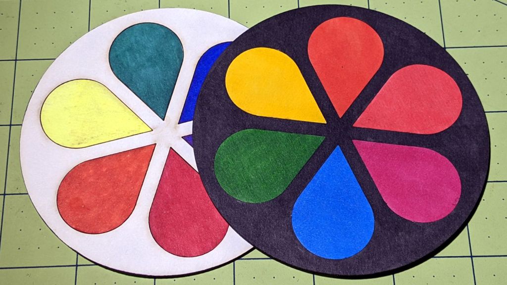
In the meantime, a black frame conceals many issues:
Chipboard coaster – rounded petals – front vs back cut
I must up my coloring game; those fat-tip markers just ain’t getting it done.
This file contains hidden or bidirectional Unicode text that may be interpreted or compiled differently than what appears below. To review, open the file in an editor that reveals hidden Unicode characters.
Learn more about bidirectional Unicode characters
This file contains hidden or bidirectional Unicode text that may be interpreted or compiled differently than what appears below. To review, open the file in an editor that reveals hidden Unicode characters.
Learn more about bidirectional Unicode characters