Ed Nisley's Blog: Shop notes, electronics, firmware, machinery, 3D printing, laser cuttery, and curiosities. Contents: 100% human thinking, 0% AI slop.
Category: Software
General-purpose computers doing something specific
Some years ago we acquired a free quartet of aluminum-frame patio chairs in need of new straps and feet. Eventually enough straps broke to force me to re-strap the things and I finally got around to replacing the badly worn OEM feet:
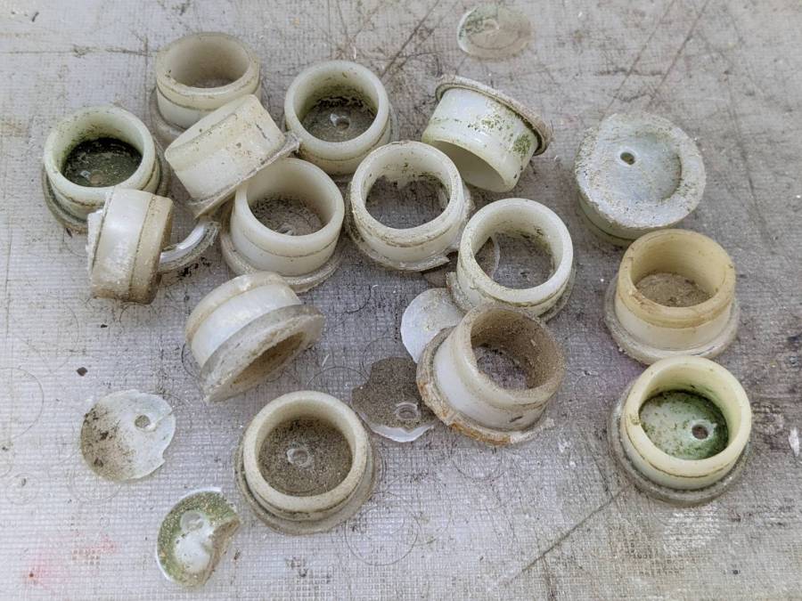
Patio Chair Foot Adapter – OEM feet
The small drilled holes let me yoink most them out with sheet-metal screw attached to a slide hammer, then apply the Designated Prydriver to the most recalcitrant / broken ones.
Some feet had worn enough to expose the aluminum tubes, but most had at least a thin layer of plastic:
Patio Chair Foot Adapter – OEM foot erosion
Obviously, I should have stripped and repainted the frames (if that’s possible, as they’re probably powder-coated), but a man’s gotta know his limitations and this job needed to get done.
One might think patio furniture replacement feet are cheap & readily available, but no amount of keyword engineering produced search results with any degree of assured fit, so I conjured adapters for screw-in feet from the vasty digital deep:
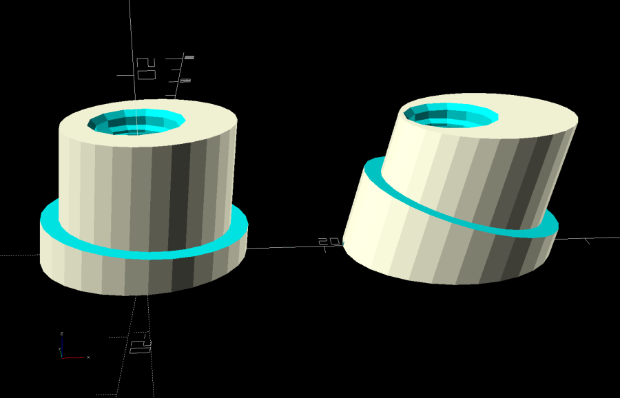
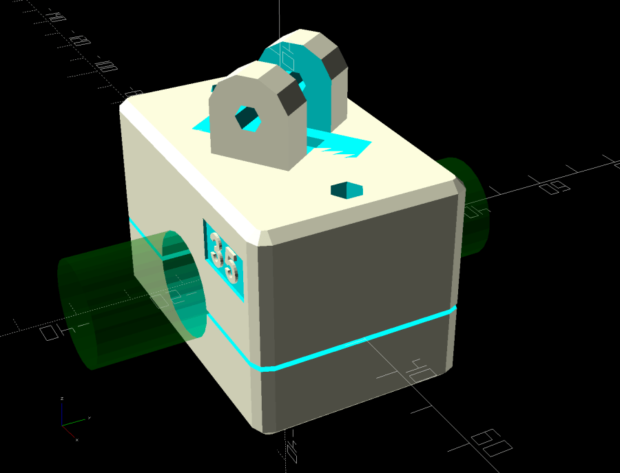
Patio Chair Foot Adapters – solid models
This was a long-awaited opportunity to explore the BOSL2 library and it worked wonderfully well. Each adapter is whittled from a huge hex nut with threads that perfectly fit the M8×1.25 stud, which stands vertically through the middle of the (slightly oval) bottom surface parallel to the floor.
The front tubes have a 5° angle with respect to the vertical:
Patio Chair Foot Adapter – front
And the rear tubes are 15° off:
Patio Chair Foot Adapter – rear
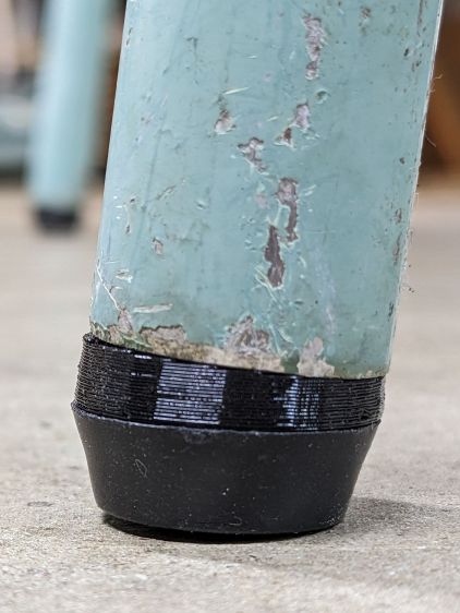
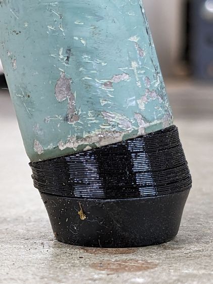
Each adapter has an orientation notch pointing toward the front of the front leg and the rear of the rear leg:
Patio Chair Foot Adapter – orientation notch
I expected to apply adhesive on the inside and outside of the adapters, but they tapped firmly into place inside the legs and the studs screwed firmly into them, so we’ll see how they survive in actual use. I expect the studs to rust after a while, but that might not be the most awful thing ever to happen.
This file contains hidden or bidirectional Unicode text that may be interpreted or compiled differently than what appears below. To review, open the file in an editor that reveals hidden Unicode characters.
Learn more about bidirectional Unicode characters
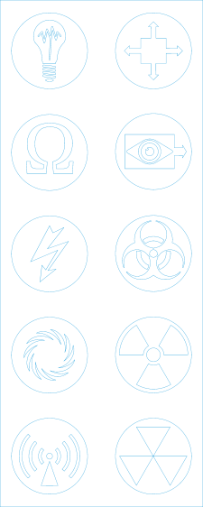
The faint blue corresponds to the LightBurn tool layer, because you’ll want to assign your own cutting parameters.
The circumscribing circle provides a convenient way to snap the pattern into something else, because the symbols in the middle are not necessarily centered around their geometric midpoint.
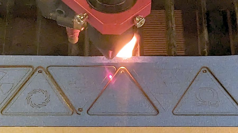
Suiting action to drawings:
SCP Earrings – black on yellow – cutting
The acrylic fire shows they’re called Danger Zone earrings for well and good reason!
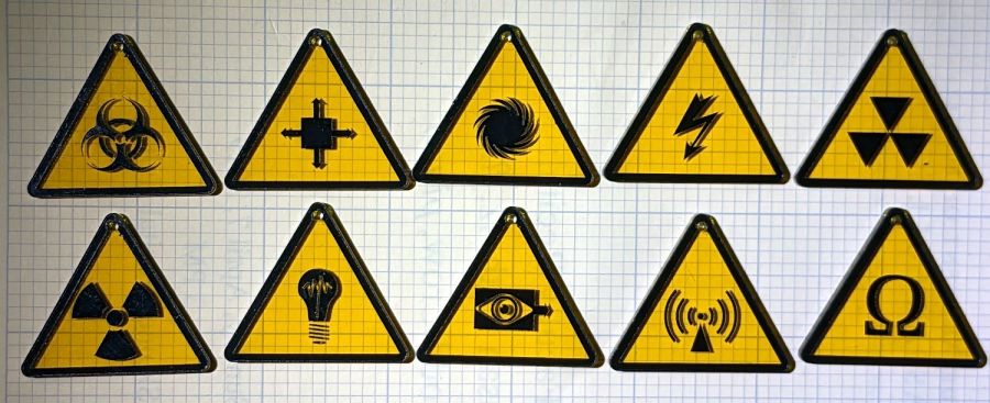
Anyhow, weeding the black vinyl produces crisp results:
SCP Earrings – black on yellow – overview
The fallout shelter symbol (top right) should have a circle around it, but that’s in the nature of fine tuning. It’s also not part of the SCP canon, but it kinda goes along with the radiation warning sign.
They’re cut from transparent amber non-edge-lit acrylic with black vinyl PSA patterns:
SCP Earrings – black on yellow – detail
Still not enough to get me to go full-frontal Mr Clean.
I have no explanation for the different stroke widths, other than that SVG files seem to maintain a memory of every transformation applied to any object. LightBurn doesn’t use the stroke widths, so it should work out just fine.
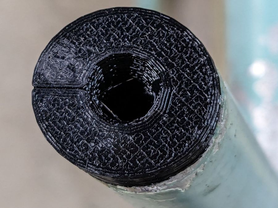
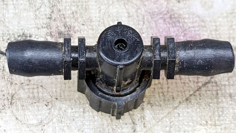
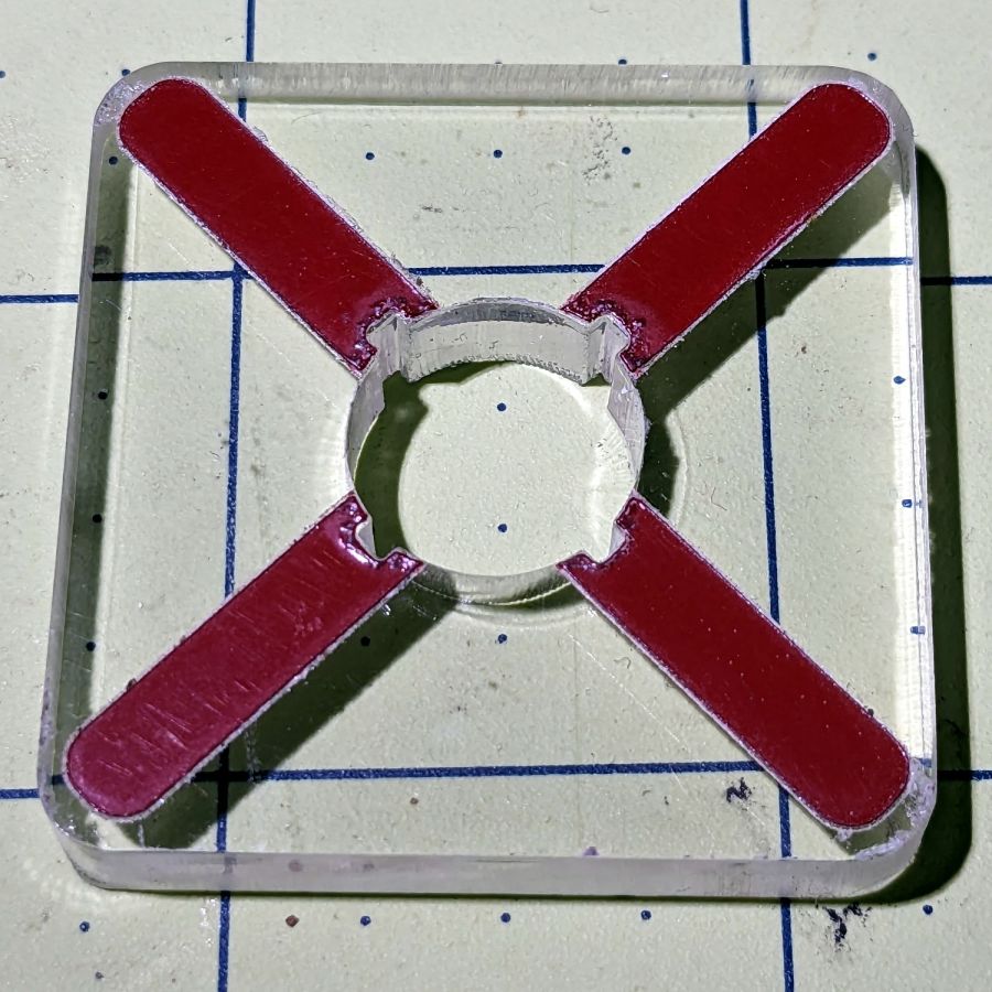
One of the Dripworks Micro-Flow valves in Mary’s garden started spraying water through the mold mark in the middle of the bottom:
Dripworks valve – bottom view
The autopsy produced a handful of pieces and inconclusive results: no visible holes or cracks.
Having replaced it with a new (and drilled out) valve, I scanned the underside of the severed valve knob, blew out the contrast, imported it into LightBurn, and got a reasonable approximation to the outline:
LightBurn geometry over image
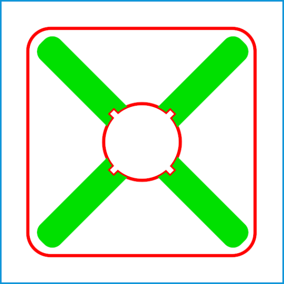
A few more tweaks, weld the outline together, add some markers, and it’s ready for cutting:
Dripworks valve helper – LB layout
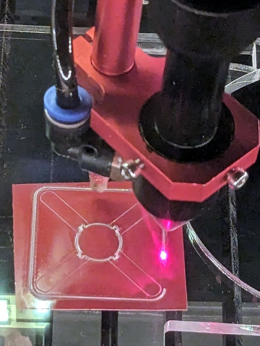
Having just done some earrings with PSA vinyl figures, I changed the (green) engraved layer to a kiss cut and Fired The Laser:
Dripworks valve helper – cutting
The mess in the vinyl around the through cuts in the ¼ inch acrylic sheet suggest engraving will work better. Lesson learned.
A few minutes of weeding produced a finger-friendly helper with scorches around the central ends of the vinyl:
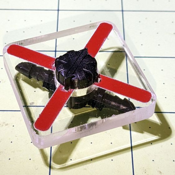
Dripworks valve helper
But it fits right over the knob, which was the whole point of the exercise:
Dripworks valve helper – in use
Now Mary can adjust the valve without squinting at obscure black-on-black shapes atop the knob.
I decided keying the helper to the knob so it fit in only one orientation on the knob would be a hindrance, because there’s no easy way to determine their mutual orientation without the aforementioned squinting. Now it’s a matter of putting the helper over the knob, turning it at most a quarter-turn until it drops around the knob, then making another quarter of a turn to put the other red marks parallel to the hose: if it was on, it’s now off, and vice versa.
After the PSA vinyl peels away, I’ll make another one with engraved lines and any other improvements.
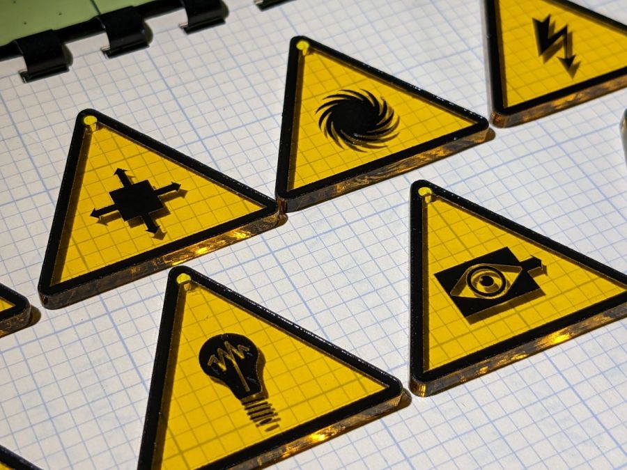
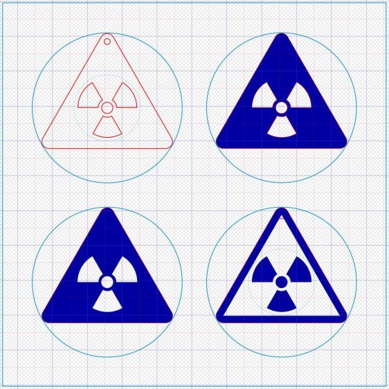
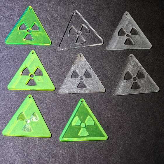
Some geometry review and a bit of fiddling with LightBurn produced regularized patterns suitable for laser cuttery:
Danger Zone Earrings – radioactive – handful
A key trick: circumscribe the figure with a circle on a tool layer, then group the whole mess together, so that the center of the circle coincides with the desired center of the figure. In particular, the geometric center of an equilateral triangle is not at the center of its vertical extent:
Danger Zone Earrings – radioactive – LB layout
The dark blue layer engraves the surface, the red layer cuts through 3 mm acrylic, and the light blue layer is the tooling.
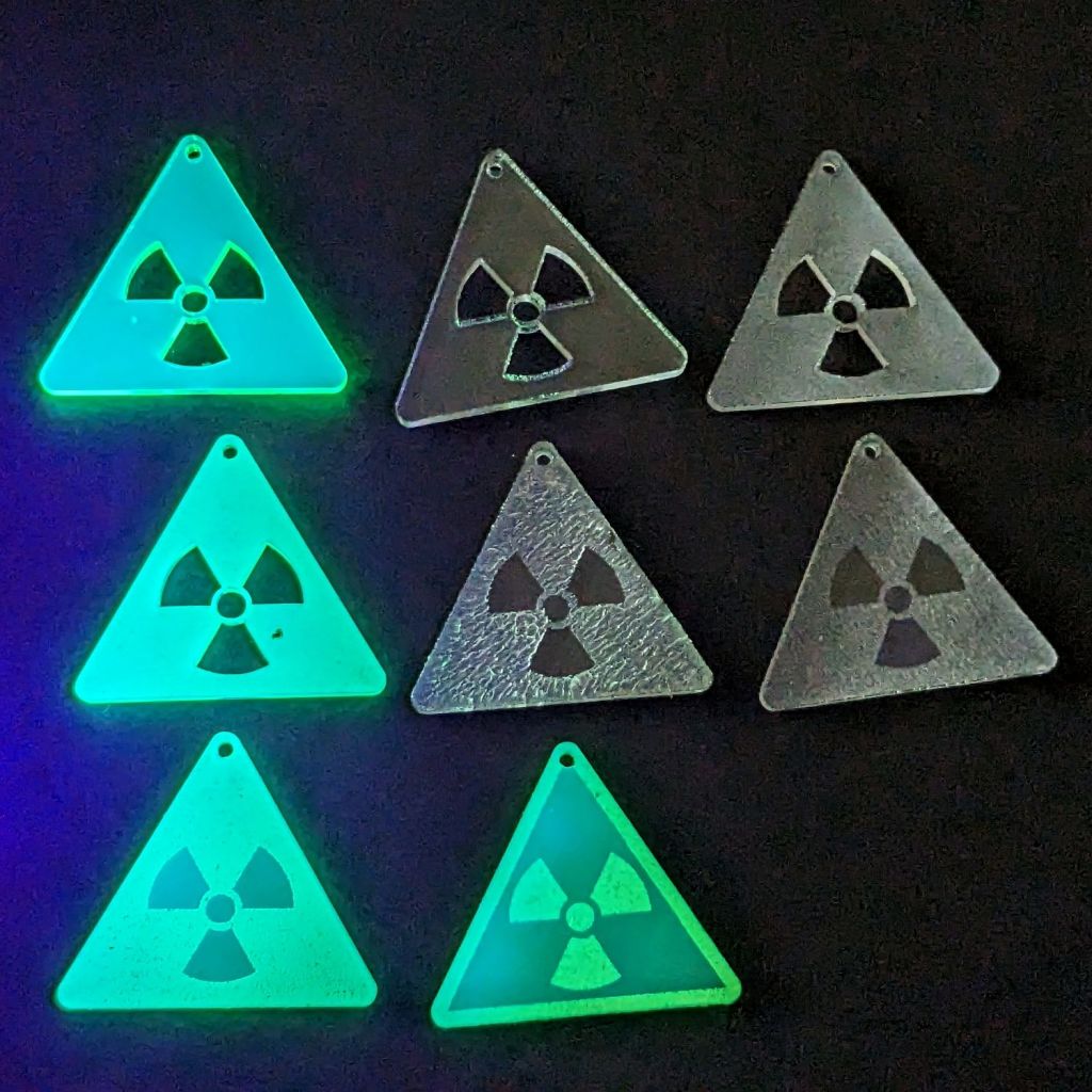
I like the edge-lit ones, although the simplicity of laser-cut clear acrylic is hard to beat:
Danger Zone Earrings – radioactive – white light
Wearing them in a place flooded with UV radiation would set you apart:
Danger Zone Earrings – radioactive – GITD UV
The careful observer will note stress cracking in the two clear earrings in the middle row. Those came from the vintage paper-covered acrylic sheet and I used alcohol to clean off the not-quite-vaporized glue just to see if isopropyl alcohol would behave differently than denatured alcohol. Nope, the cracks appear instantly.
Peeling the paper and engraving the bare surface produced the clear-frosted earring in the upper right, with the radiation symbol cut out of the sheet. Engraving without surface protection tends to deposit vaporized acrylic dust everywhere, so it would require hand cleaning without the cutouts.
The cutouts get 0.1 mm inward offsets to slightly increase the wall thickness around that central circle.
One combination I didn’t try: engrave the triangle perimeter for emphasis and cut out the symbol for contrast with edge-lit acrylic.
Dropping other symbols into place should be straightforward, with the center of the circumcircle as the snap target.
Using Bash arrays is an exercise in masochism, but I got to recycle most of the oddities from the previous script, so it wasn’t a dead loss.
The cameras use individually unique / screwy / different filesystem layouts, so the script must have individual code to both copy the file and decapitalize the file extensions. This prevents using a single tidy function, although laying out the code in case statements keyed by the camera name helps identify what’s going on.
My previous approach identified the MicroSD cards by their UUIDs, which worked perfectly right up until the camera reformats the card while recovering from a filesystem crash and installs a randomly generated UUID. Because there’s no practical way to modify an existing UUID on a VFAT drive, I’m switching to the volume label as needed:
In particular, note the two UUIDs for the M20 camera: there’s a crash and reformat in between those two lines. The two C100 cameras started out with labels because the M20 taught me the error of my ways.
The script simply iterates through a list array of the cameras and tries to mount the corresponding MicroSD card for each one: the mount points are cleverly chosen to match the camera names in the array. Should the mount succeeds, an asynchronous rsync then slurps the files onto the bulk video drive.
With all the rsync operations running, the script waits for all of them to complete before continuing. I don’t see much point in trying to identify which rsync just finished and fix up its files while the others continue to run, so the script simply stalls in a loop until everything is finished.
All in all, the script scratches my itch and, if naught else, can serve as a Bad Example™ of how to get the job done.
A picture to keep WordPress from reminding me that readers respond positively to illustrated posts:
This file contains hidden or bidirectional Unicode text that may be interpreted or compiled differently than what appears below. To review, open the file in an editor that reveals hidden Unicode characters.
Learn more about bidirectional Unicode characters
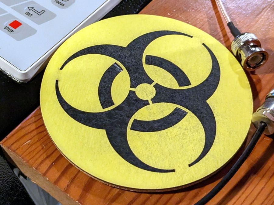
That’s built directly from the original specs to get the spacing and symmetries correct. The freebies I could find all suffered from various degrees of bad design & layout.
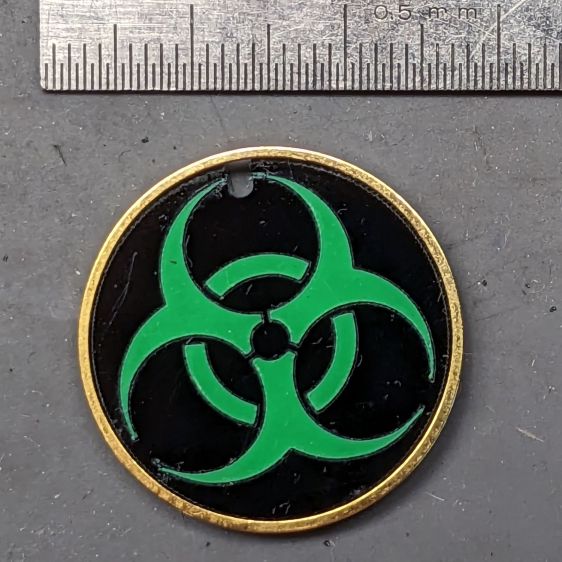
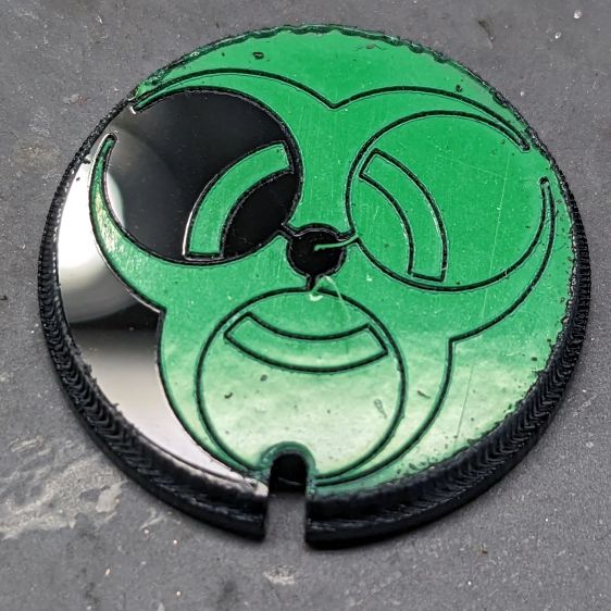
Shrunken down to 25 mm OD, the tips become vanishingly small:
Biohazard earring – vinyl sample
It’s the same laser-safe polyurethane vinyl as the SD card reader, this time applied to 3 mm black acrylic. The “gold” ring is just parked in place, as this one wasn’t presentation-quality.
Contrary to the usual transfer-tape method of applying PSA vinyl, I stuck the sheet to the acrylic before cutting, then weeded it directly off the acrylic:
Biohazard earring – vinyl weeding
Kiss-cutting the vinyl with dot mode ate into the acrylic, but the soon-to-be-weeded areas protected the surroundings and the result came out looking pretty good. To me, anyhow.
Flushed with success, I tried some almost certainly not laser safe glow-in-the-dark tape:
Biohazard earring – GITD weeding fail
The mess in the upper left is the tape’s double-sided adhesive intended to hold the glowy layer in place forever. Of course it weeded poorly!
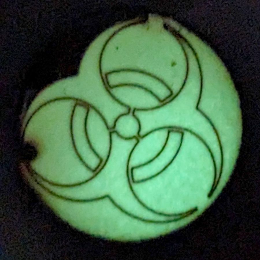
Seen in its natural environment, however, weeding may not be necessary:
Biohazard earring – GITD tape glow
Engraving the rebated rim leaves quite a bit of debris & scorch marks around the perimeter. A mask layer atop the GITD tape seems like a Good Idea™.
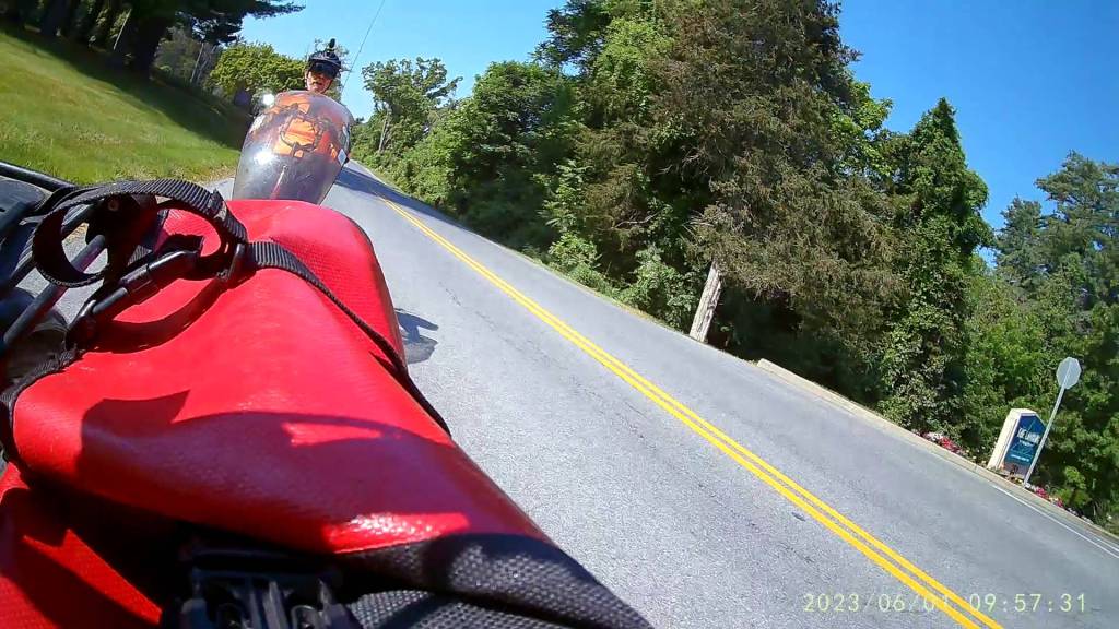
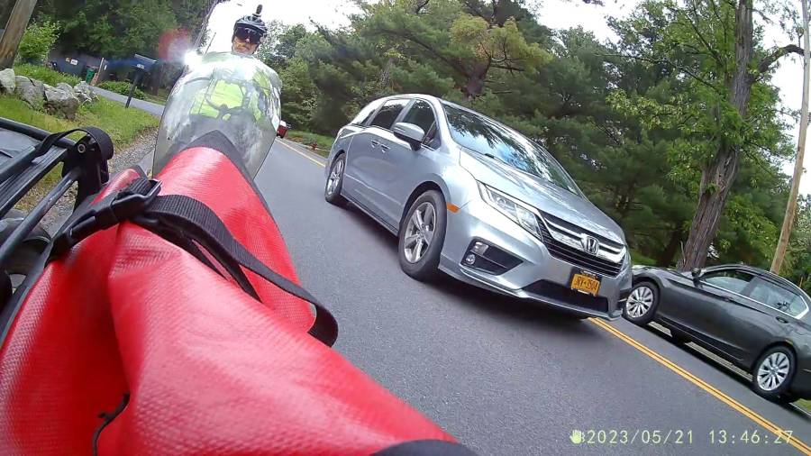
As expected, the internal battery does not last for our usual hour-long rides, so the cameras now operate in “car mode”: recording starts when we plug in the USB battery pack and stops shortly after unplugging.
I started with the waterproof case on my bike:
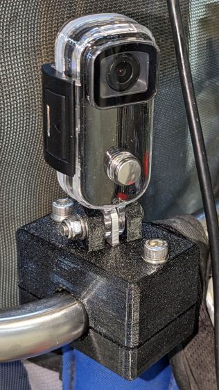
Tour Easy – SJCAM C100 mount – installed
Which (obviously) does not allow for an external battery, so they’re now in the “frame” mount. The hatch covering the MicroSD card and USB Micro-B connector (and a Reset button!) is on the bottom of the camera, but (fortunately) the whole affair mounts up-side-down and the settings include an image flip mode.
The ergonomics / user interface of this whole setup is terrible:
The camera’s flexible hatch is recessed inside the frame far enough that it cannot be opened without using a small & sharp screwdriver
The USB jack is slightly off-center, so lining the plug up with the camera body doesn’t align it with the jack
The MicroSD card is in a push-to-release socket, but its raised ridge faces the hatch flap and cannot be reached by a fingernail. I added a small tab that helps, but it’s difficult to grasp.
Extracting the video files from the camera through the app is an exercise in frustration. Having already figured out how to do this for the other cameras in the fleet, it’s easier to fumble with the MicroSD card.
I devoutly hope we never really need any of the videos.


