
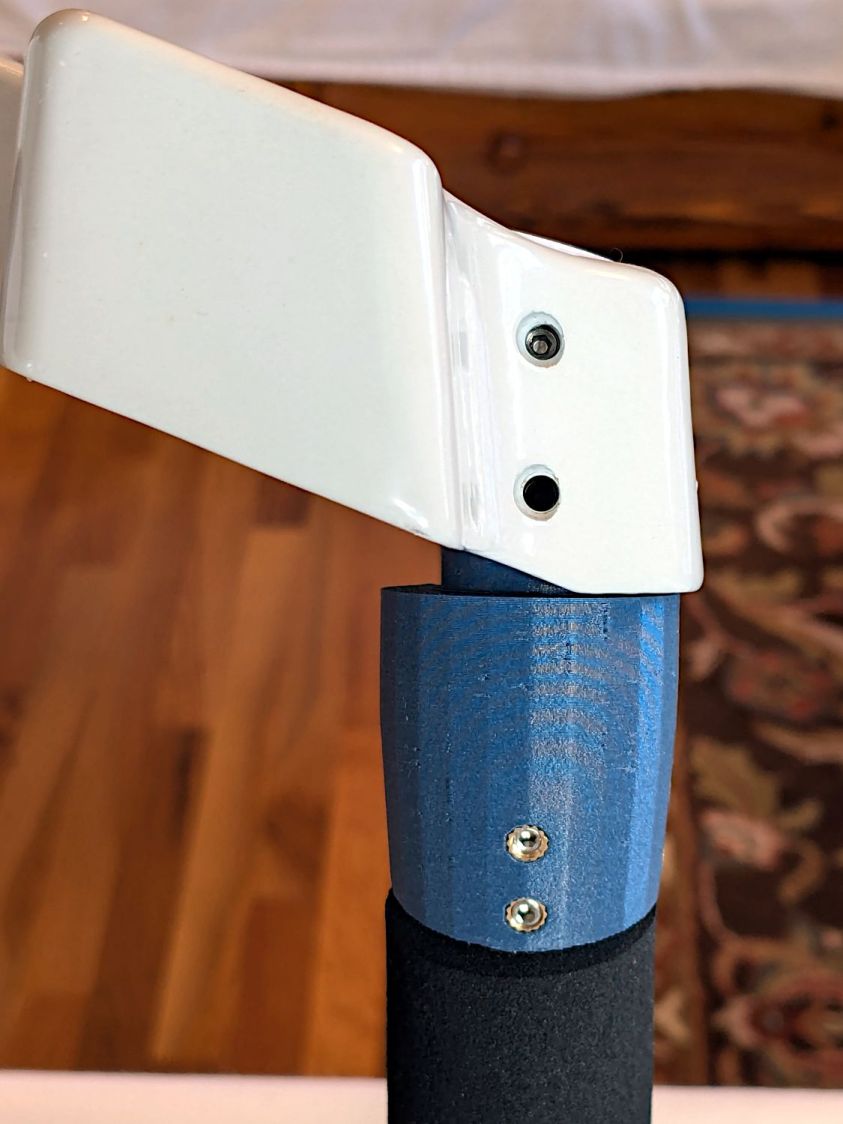
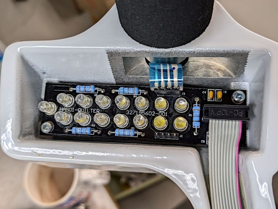
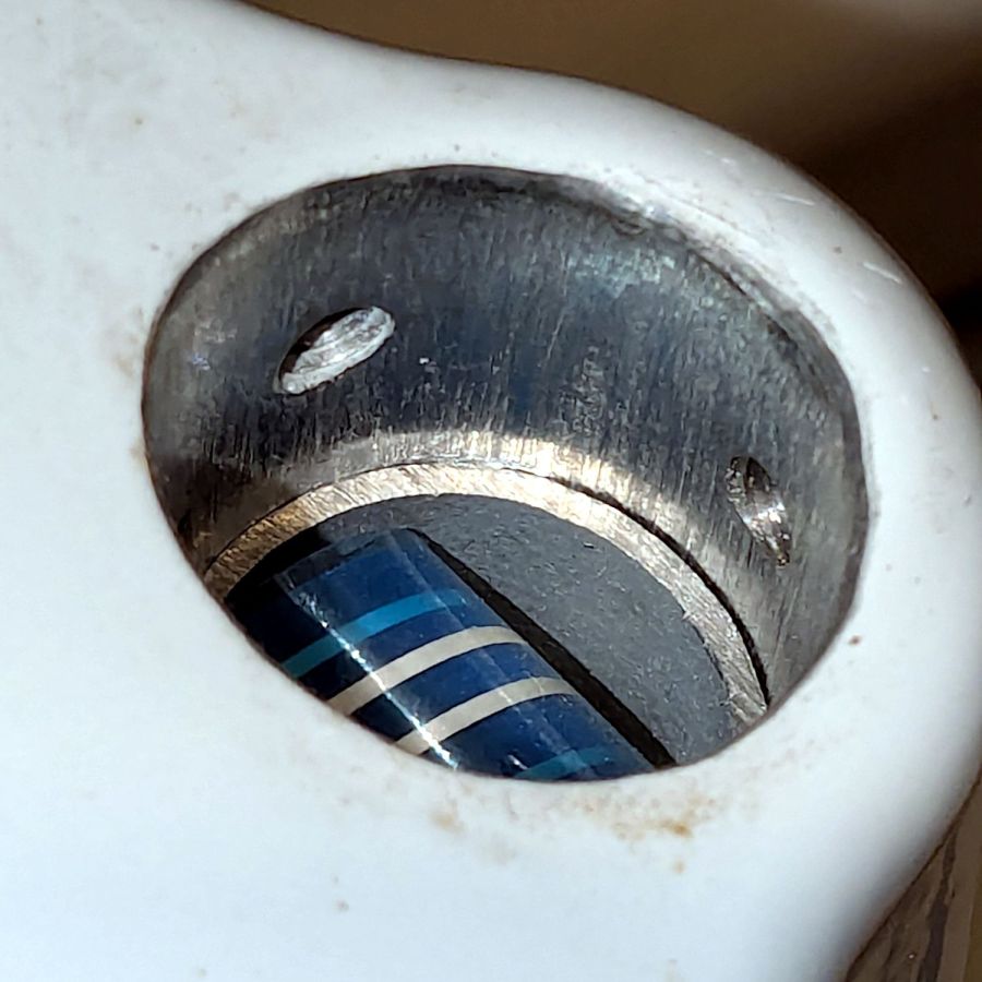
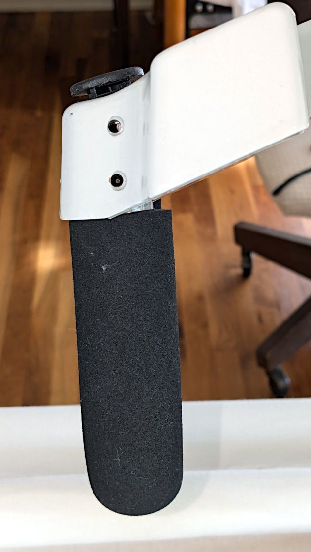
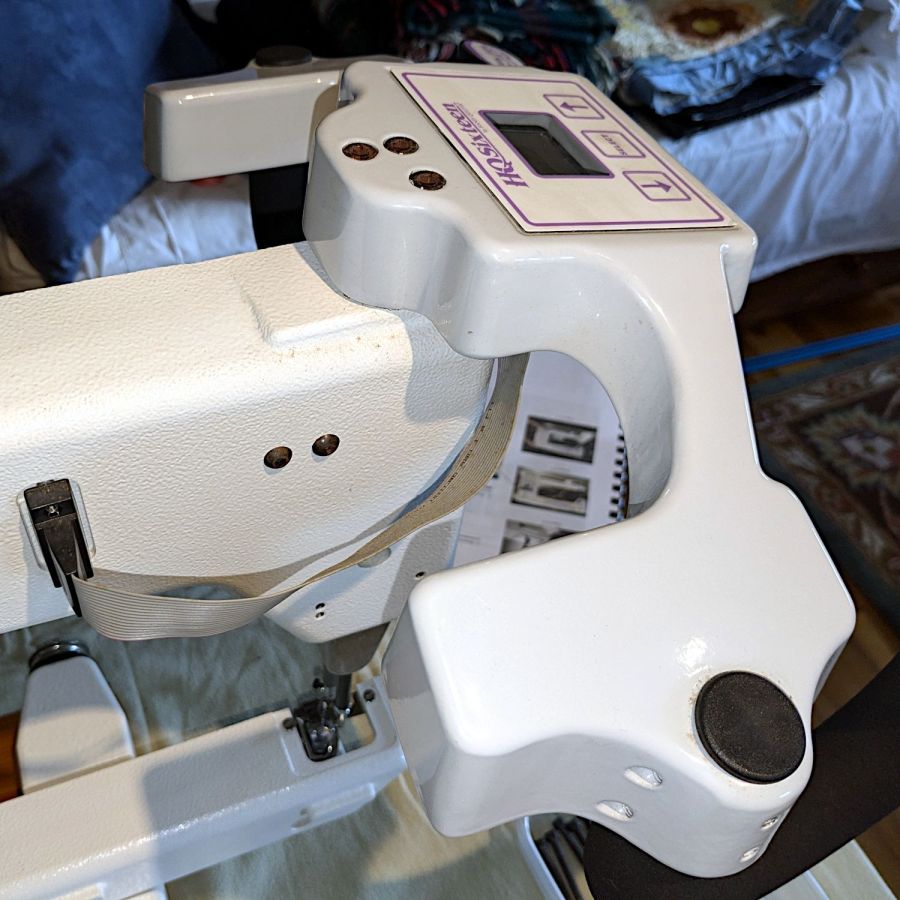
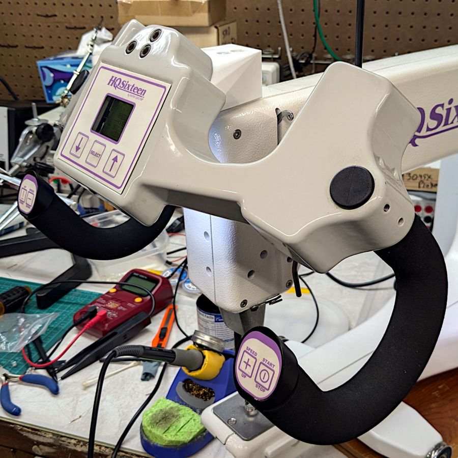
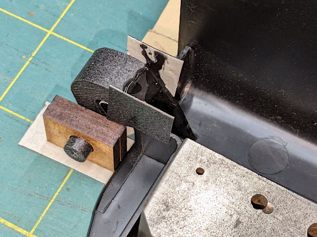
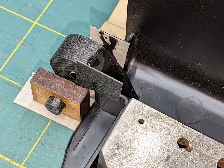
The angle block joins the aluminum grip with the plug sticking into HQ Sixteen’s handlebar control base:
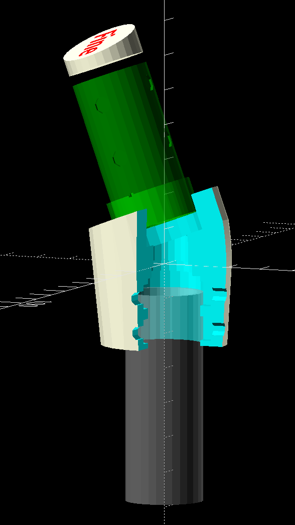
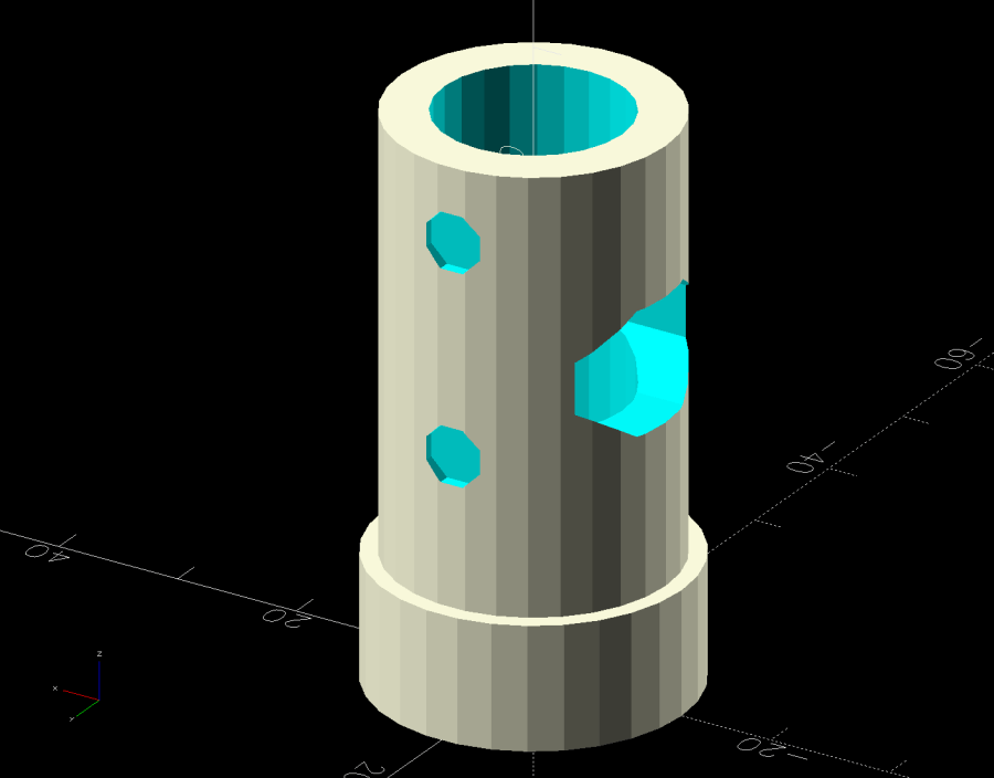
Because I don’t know the exact angle until Mary puts more hours on the machine, the OpenSCAD code can tilt the plug from 10° to 30° with respect to the original grip. The bent part of the model consists of a succession of hulls around adjacent slices:

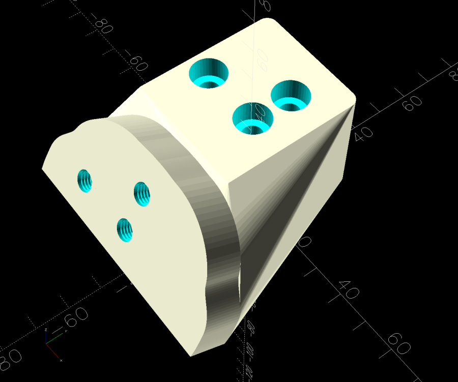
An overall hull() then gloms everything into one solid lump, with all the negative features removed from it:

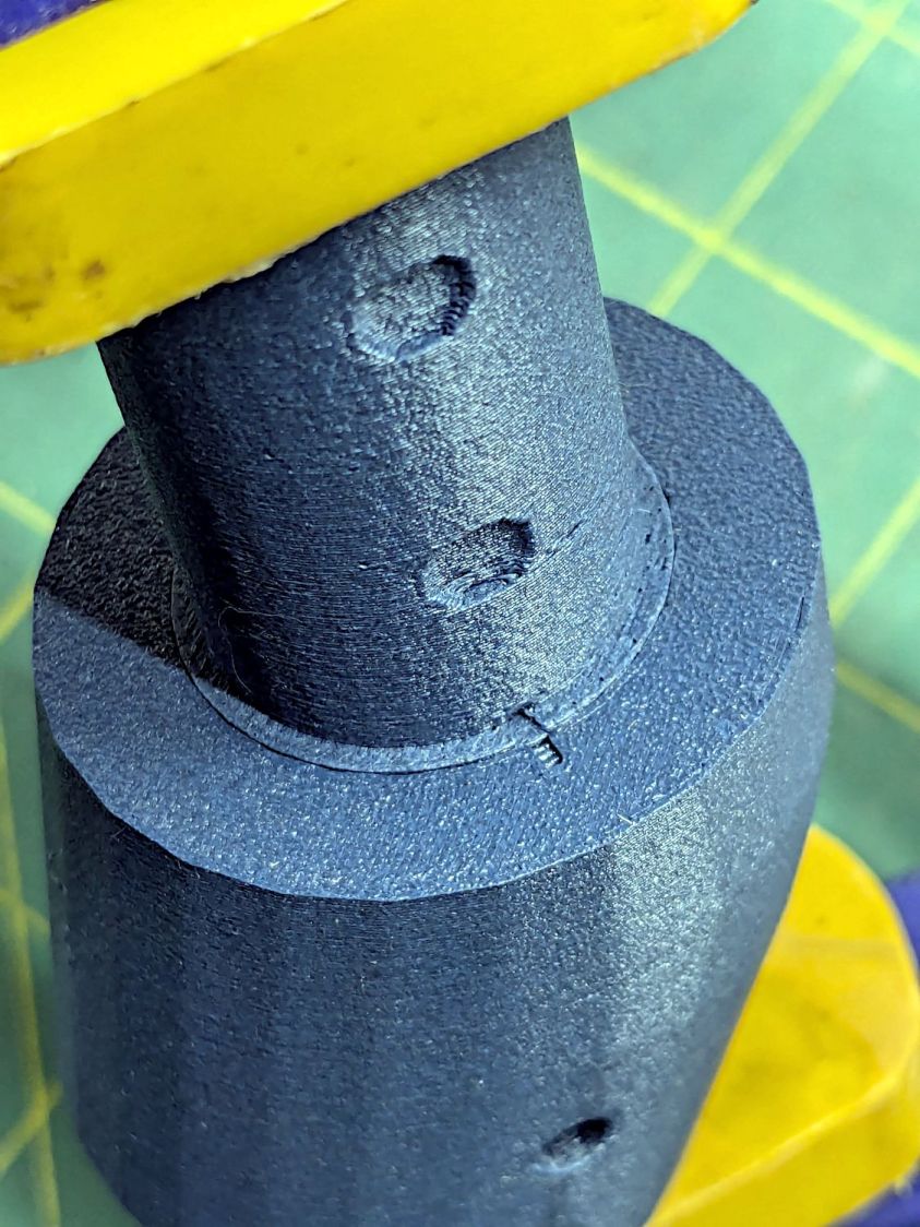
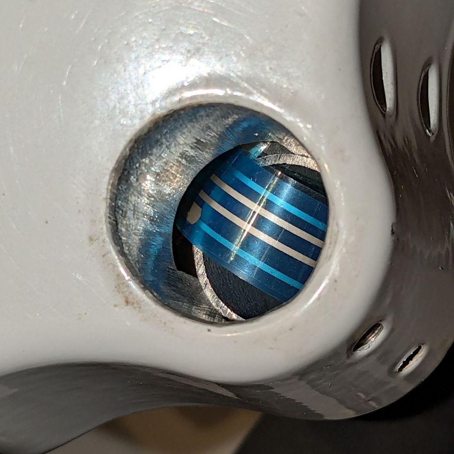
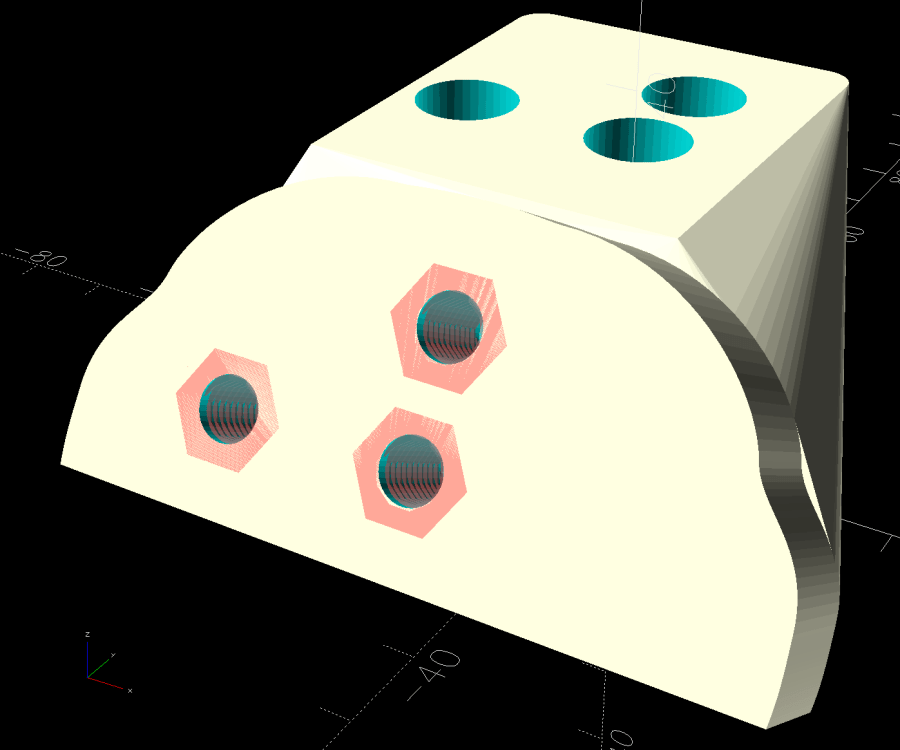
After a brief flirtation with heat-staked brass inserts, four setscrews threaded into steel square nuts secure the original grip in the bottom:

A screw behind that big washer pulled the nuts firmly into their sockets, where they stay without any adhesive. The square recesses include a little adder based on the curvature of the hole to sink the nuts deep enough:

I made the block’s OD large enough to accommodate the brass inserts and hope it’s chunky enough to withstand the force from the setscrews. The inserts tended to creep outward after being snugged down, but the square nuts seem stable against the recesses.
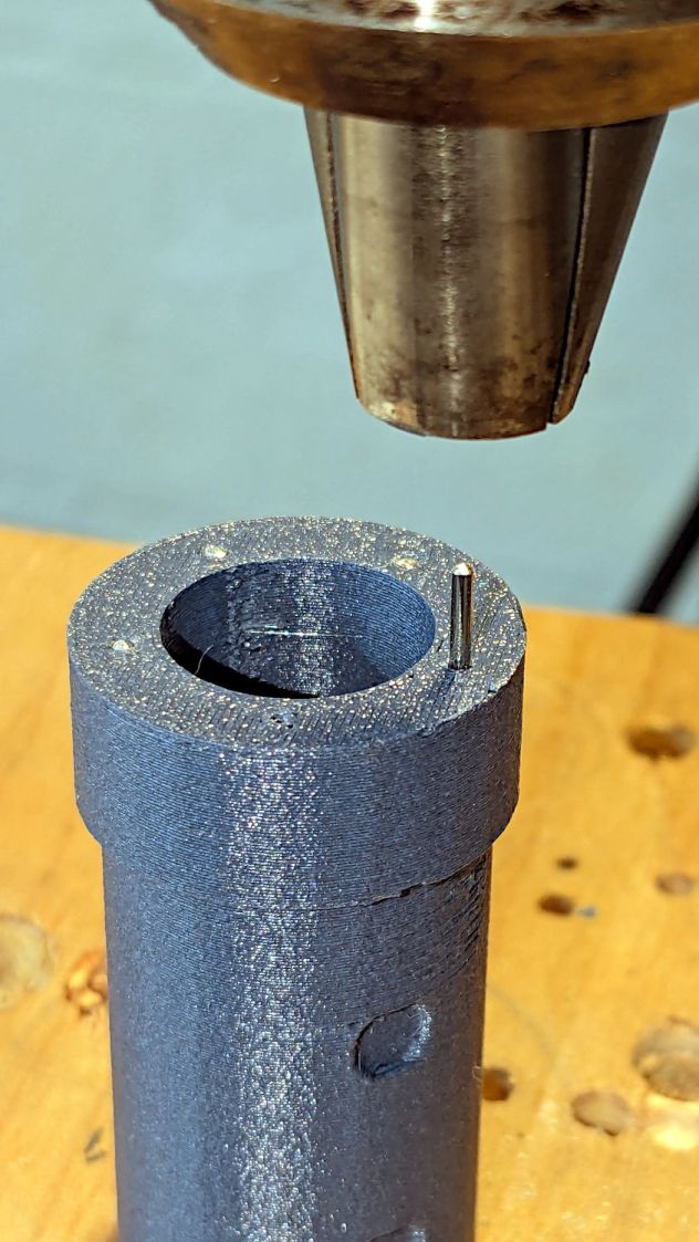
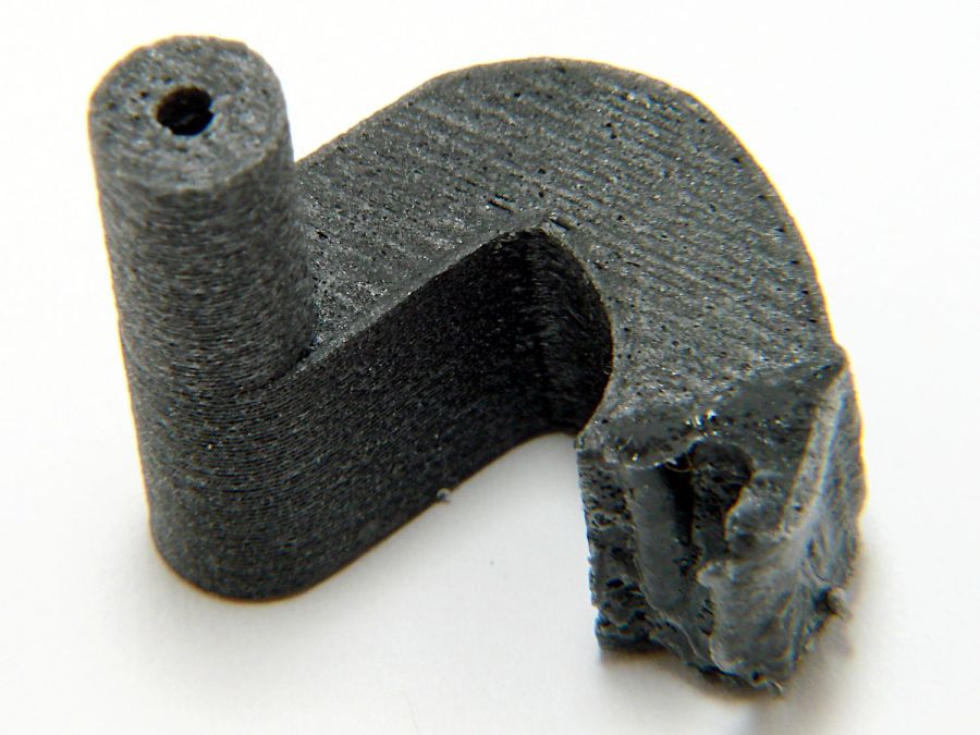
The block prints with the top surface against the platform to produce a clean recess for the plug, which requires support material for the ring around the bore. Because the ring sags slightly against the support, the model makes the recess 0.4 mm deeper, but the next iteration gets a little more:
Not that it makes much difference.
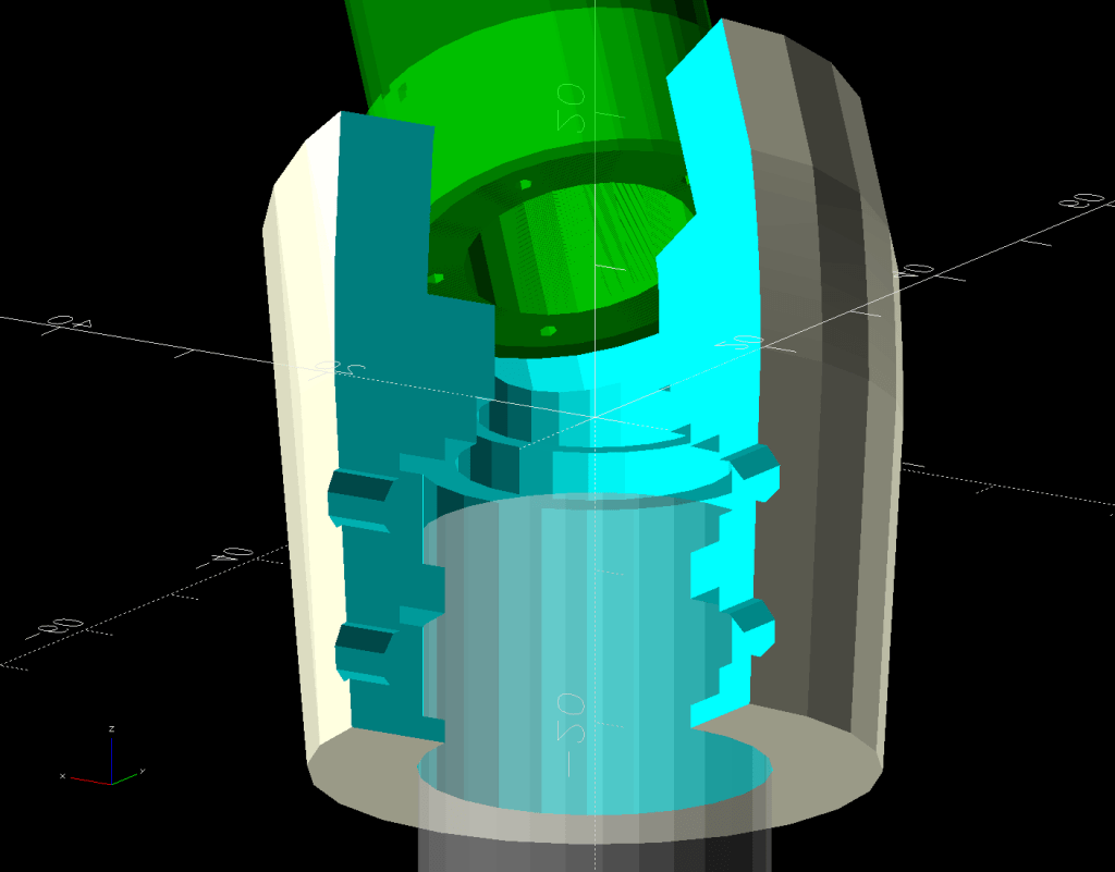
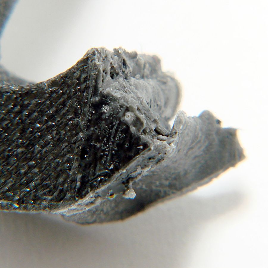
The bore from the grip meets the bore from the plug in a sphere centered at the bottom of the plug recess:
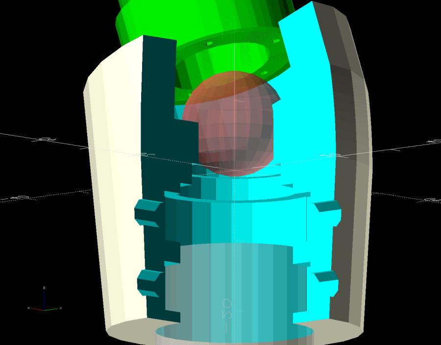
A ball joint seems the best way to join a pair of intersecting cylinders, if you have room for the sphere, and eliminates a whole bunch of computations figuring the cylinder lengths; they just meet at about the center of the sphere and you’re done without anything sticking out. I’d like to pretend that was the first idea I had, but …
The OpenSCAD code can add more length to the bottom of the block, in the event Mary wants the grips lower:

That obviously increases the lever arm applied to the plug, but we’ll burn that bridge when we come to it.
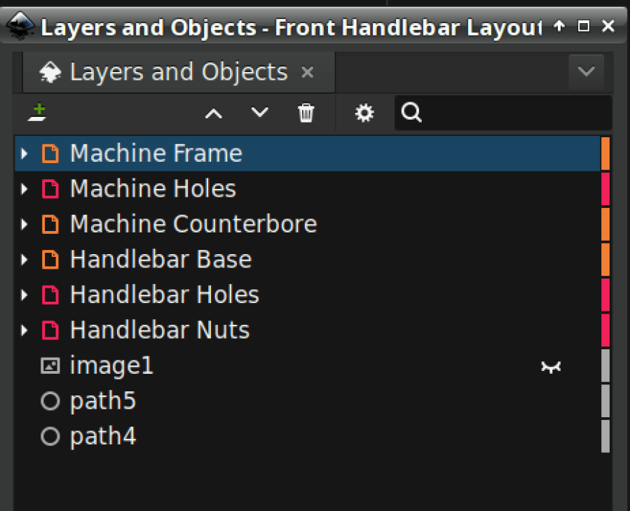
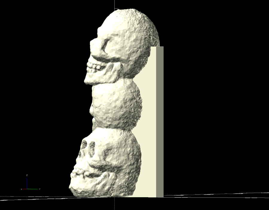
This lineup shows the progression from the first pass to something that might actually work:
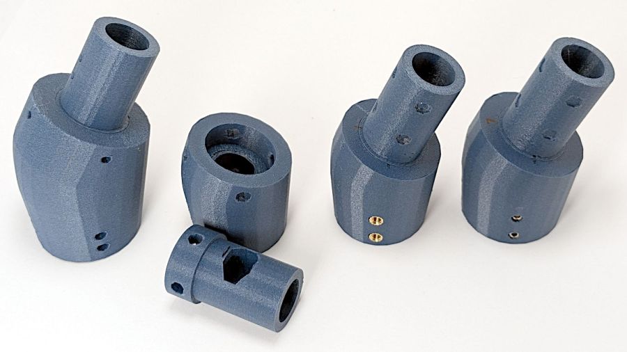
Rapid prototyping FTW!
The OpenSCAD source code as a GitHub Gist:
| // Handiquilter HQ Sixteen front handlebar grip angle mount | |
| // Ed Nisley – KE4ZNU | |
| // 2024-11-29 | |
| include <BOSL2/std.scad> | |
| Layout = "Show"; // [Show,Build,Plug,Block,Covers,Cover] | |
| Material = "All"; // [All,Cover,Text] | |
| // Angle w.r.t. base | |
| GripAngle = 20; // [10:30] | |
| // Plug glued, not screwed | |
| PlugGlue = true; | |
| // Square nuts, not inserts | |
| SquareNuts = true; | |
| // Additional length of bottom | |
| AddLength = 0; // [0:20] | |
| // Separation in Show display | |
| Gap = 5; // [0:20] | |
| /* [Hidden] */ | |
| HoleWindage = 0.1; | |
| Protrusion = 0.1; | |
| NumSides = 2*3*4; | |
| ID = 0; | |
| OD = 1; | |
| LENGTH = 2; | |
| Grip = [19.7,22.4,20.0]; // (7/8)*INCH = 22.2 mm + roughness, LENGTH=OEM insertion depth | |
| GripRadius = Grip[OD]/2; // used everywhere | |
| Plug = [15.0,Grip[OD],45.0]; // inserts into handlebar base | |
| PlugRim = [Plug[ID],25.0,10.0]; // … sits against handlebar base | |
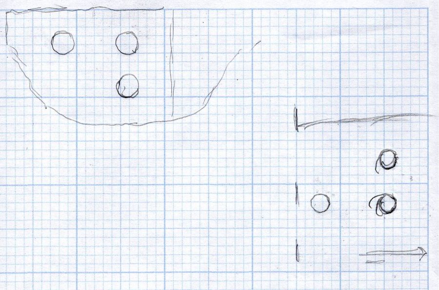
| BaseScrewPositions = [[11.0,12.0],[27.0,29.0]]; // setscrew offsets from rim top: side,rear | |
| BaseCutout = [Plug[OD]/2,Plug[ID],10]; // cable cutout into base | |
| BaseCutoutOffset = 18.0; // … centerline position w.r.t. rim | |
| WallThick = 7.0; // should at least fit insert length | |
| SupportSag = 0.4; // vertical sag over support structure | |
| MidLength = AddLength + 3.0; // total length allowing for grip tube stop | |
| TopOD = PlugRim[OD] + 2*WallThick; | |
| BotOD = Grip[OD] + 2*WallThick; | |
| BaseScrew = [4.0,4.8 + HoleWindage,1.0]; // HQ 10-32 screws, LENGTH=capture dent | |
| Insert = [5.4,6.0,6.0]; // M4 inserts in plug rim | |
| //Insert = [4.0,5.0,5.0]; // M4 inserts in plug rim | |
| Screw = [3.5,4.0,1]; // M4 screws through angle block to inserts | |
| ScrewHeadOD = 7.4 + 0.4; // M4 BHCS head + comfort | |
| SquareNut = [4.0,7.0,3.0 + 0.4]; // M4 square nut LENGTH + inset allowance | |
| NutInset = GripRadius – sqrt(pow(GripRadius,2) – pow(SquareNut[OD],2)/4); | |
| PinOD = 1.2; // plug reinforcing pins | |
| NumPins = 5; | |
| CoverThick = [3.5,9.5]; // low and high sides of grip covers | |
| CoverAngle = atan((CoverThick[1] – CoverThick[0])/Plug[OD]); | |
| LogoText = ["Sew","Fine"]; | |
| LogoFont = "Fira Sans Condensed:style=SemiBold"; | |
| LogoSize = 7.5; | |
| LogoColor = "Red"; | |
| LogoThick = 0.8; | |
| //———- | |
| // Simulator for aluminum plug replacing handlebar in base | |
| module BasePlug() { | |
| difference() { | |
| union() { | |
| tube(Plug[LENGTH],(Plug[OD] – HoleWindage)/2,Plug[ID]/2,anchor=DOWN); | |
| tube(PlugRim[LENGTH],PlugRim[OD]/2,PlugRim[ID]/2,anchor=DOWN); | |
| } | |
| up(BaseCutoutOffset + PlugRim[LENGTH]) | |
| left(Plug[OD]/4) | |
| resize(BaseCutout) | |
| yrot(90) zrot(180/8) | |
| cylinder(d=1,h=1,$fn=8,center=true); | |
| up(PlugRim[LENGTH]) | |
| right(PlugRim[OD]/2 – 1.0) | |
| cube([2.0,1.0,1.0],center=true); | |
| for (i = [0:NumPins – 1]) | |
| zrot(i*360/NumPins + 180/NumPins) | |
| down(Protrusion) | |
| right((Plug[OD] + Plug[ID])/4) | |
| zrot(180/6) | |
| cylinder(d=PinOD,h=2*PlugRim[LENGTH],$fn=6); | |
| for (k = [0:1]) // recesses in plug to capture base setscrews | |
| for (a = [0:1]) | |
| up(PlugRim[LENGTH] + BaseScrewPositions[k][a]) | |
| zrot(a*90) | |
| right(Plug[OD]/2) | |
| yrot(90) zrot(180/8) | |
| cylinder(d=BaseScrew[OD],h=2*BaseScrew[LENGTH],$fn=8,center=true); | |
| if (!PlugGlue) | |
| for (a = [0:1]) // inserts for angle block screws | |
| up(PlugRim[LENGTH]/2) | |
| zrot(a*90) | |
| yrot(90) zrot(180/8) | |
| cylinder(d=Insert[OD],h=2*PlugRim[OD],$fn=8,center=true); | |
| } | |
| } | |
| //———- | |
| // Block fitting against handlebar base with handlebar angle | |
| module AngleBlock() { | |
| difference() { | |
| hull() { | |
| up((TopOD/2)*sin(GripAngle)) | |
| xrot(GripAngle) | |
| cylinder(d=TopOD,h=PlugRim[LENGTH],$fn=NumSides); | |
| for (a = [1:2:GripAngle+1]) | |
| up((TopOD/2)*sin(a-1)) | |
| hull() { | |
| xrot(a) | |
| cylinder(d=TopOD,h=0.1,$fn=NumSides); | |
| xrot(a-1) | |
| cylinder(d=TopOD,h=0.1,$fn=NumSides); | |
| } | |
| down(Grip[LENGTH] + MidLength) | |
| cylinder(d=(Grip[OD] + 2*WallThick),h=0.1,$fn=NumSides); | |
| } | |
| up((TopOD/2)*sin(GripAngle)) | |
| xrot(GripAngle) | |
| down(SupportSag) | |
| cylinder(d=(PlugRim[OD] + HoleWindage), | |
| h=PlugRim[LENGTH] + SupportSag + Protrusion, | |
| $fn=NumSides); | |
| up((TopOD/2)*sin(GripAngle)) | |
| sphere(d=PlugRim[ID],$fn=NumSides); | |
| cylinder(d=PlugRim[ID],h=(TopOD/2)*sin(GripAngle),$fn=NumSides); | |
| down(MidLength + Protrusion) | |
| cylinder(d=(Grip[ID] – 2.0),h=(MidLength + 2*Protrusion),$fn=NumSides); | |
| down(Grip[LENGTH] + MidLength + Protrusion) | |
| cylinder(d=(Grip[OD] + HoleWindage),h=(Grip[LENGTH] + Protrusion),$fn=NumSides); | |
| up((TopOD/2)*sin(GripAngle)) | |
| xrot(GripAngle) | |
| up(PlugRim[LENGTH]) | |
| right(PlugRim[OD]/2 + 0.9) | |
| cube([2.0,1.0,1.0],center=true); | |
| if (!PlugGlue) { | |
| for (a = [0:1]) | |
| up((TopOD/2)*sin(GripAngle)) | |
| xrot(GripAngle) | |
| up(PlugRim[LENGTH]/2) | |
| zrot(a*90) | |
| yrot(90) zrot(180/8) | |
| cylinder(d=Screw[OD],h=3*PlugRim[OD],$fn=8,center=true); | |
| for (a = [0:3]) | |
| up((TopOD/2)*sin(GripAngle)) | |
| xrot(GripAngle) | |
| up(PlugRim[LENGTH]/2) | |
| zrot(a*90) | |
| right(TopOD/2 – 2.0) | |
| yrot(90) zrot(180/8) | |
| cylinder(d=ScrewHeadOD,h=TopOD,$fn=8,center=false); | |
| } | |
| if (SquareNuts) { | |
| for (a = [0:1]) | |
| for (k = [1,3]) | |
| down(k*Grip[LENGTH]/4 + MidLength) | |
| zrot(a*90) | |
| right(BotOD/2) | |
| yrot(90) zrot(180/8) | |
| cylinder(d=SquareNut[ID],h=BotOD,$fn=8,center=true); | |
| for (a = [0:1]) | |
| for (k = [1,3]) | |
| down(k*Grip[LENGTH]/4 + MidLength) | |
| zrot(a*90) | |
| right(GripRadius + SquareNut[LENGTH]/2 – NutInset/2) | |
| yrot(90) | |
| cube([SquareNut[OD],SquareNut[OD],SquareNut[LENGTH] + NutInset],center=true); | |
| } | |
| else { | |
| for (a = [0:1]) | |
| for (k = [1,3]) | |
| down(k*Grip[LENGTH]/4 + MidLength) | |
| zrot(a*90) | |
| right(BotOD/2) | |
| yrot(90) zrot(180/8) | |
| cylinder(d=Insert[OD],h=BotOD,$fn=8,center=true); | |
| } | |
| } | |
| } | |
| //———- | |
| // Chip fitting against handlebar base matching top angle | |
| // Text will be invisible until sliced | |
| module GripCover(loc=LEFT,matl="Cover") { | |
| if (matl == "Text" || matl == "All") | |
| color(LogoColor) | |
| down(matl == "All" ? 0.01 : 0.0) | |
| text3d(LogoText[loc == LEFT ? 0 : 1],LogoThick,LogoSize,LogoFont, | |
| orient=DOWN,anchor=TOP,atype="ycenter"); | |
| if (matl == "Cover" || matl == "All") | |
| difference() { | |
| intersection() { | |
| yrot(loc == RIGHT ? -CoverAngle : CoverAngle) | |
| cylinder(d=Plug[OD],h=(CoverThick[0] + CoverThick[1]),anchor=CENTER); | |
| cube(2*Plug[OD],anchor=BOTTOM); | |
| } | |
| text3d(LogoText[loc == LEFT ? 0 : 1],LogoThick,LogoSize,LogoFont, | |
| orient=DOWN,anchor=TOP,atype="ycenter"); | |
| } | |
| } | |
| //———- | |
| // Build things | |
| if (Layout == "Cover") { | |
| GripCover(LEFT,Material); | |
| } | |
| if (Layout == "Covers") { | |
| left(Plug[OD]) GripCover(LEFT,"Cover"); | |
| left(Plug[OD]) GripCover(LEFT,"Text"); | |
| right(Plug[OD]) GripCover(RIGHT,"Cover"); | |
| right(Plug[OD]) GripCover(RIGHT,"Text"); | |
| } | |
| if (Layout == "Plug") | |
| BasePlug(); | |
| if (Layout == "Block") | |
| AngleBlock(); | |
| if (Layout == "Show") { | |
| up((TopOD/2)*sin(GripAngle) + Protrusion) | |
| xrot(GripAngle) | |
| up(Plug[LENGTH] + CoverThick[1] + Gap) | |
| yrot(180 + CoverAngle) | |
| GripCover(RIGHT,"All"); | |
| up((TopOD/2)*sin(GripAngle) + Protrusion) | |
| xrot(GripAngle) | |
| up(Gap) | |
| color("Lime",0.75) | |
| BasePlug(); | |
| render() | |
| difference() { | |
| AngleBlock(); | |
| back(50) right(50) | |
| cube(100,center=true); | |
| } | |
| color("Silver",0.5) | |
| down(MidLength + Gap) | |
| tube(3*Grip[LENGTH],GripRadius,Grip[ID]/2,anchor=TOP); | |
| } | |
| if (Layout == "Build") { | |
| mirror_copy([1,0,0]) { | |
| right(BotOD) { | |
| up((TopOD/2)*sin(GripAngle) + PlugRim[LENGTH]*cos(GripAngle) + Protrusion) | |
| xrot(180 – GripAngle) | |
| AngleBlock(); | |
| back(1.5*max(TopOD,BotOD)) | |
| BasePlug(); | |
| } | |
| } | |
| fwd(60) { | |
| left(Plug[OD]) GripCover(LEFT,"Cover"); | |
| right(Plug[OD]) GripCover(RIGHT,"Cover"); | |
| } | |
| fwd(60) { | |
| left(Plug[OD]) GripCover(LEFT,"Text"); | |
| right(Plug[OD]) GripCover(RIGHT,"Text"); | |
| } | |
| } |


