Ed Nisley's Blog: Shop notes, electronics, firmware, machinery, 3D printing, laser cuttery, and curiosities. Contents: 100% human thinking, 0% AI slop.
Category: Software
General-purpose computers doing something specific
Rather than fiddle with the GUI program for my Yubikey, I use the ykman CLI program for TOTP authentication, because there’s always a command prompt / terminal open on the portrait monitor:
ykman oath accounts code -s ama
161413
Double-click to select the number in the terminal, then either copy-n-paste or middle-click into the target field of whatever needs convincing I am truly me, myself, and I.
I finally got a Round Tuit and piped the output into xclip to put the number into the clipboard:
ykman oath accounts code -s ama | xclip
Which lets me go directly to pasting or middle-clicking.
The command history is big enough that I now type only:
Ctrl-R ama
Which brings up the most recent version of the command, whereupon I whack Enter to execute it. Similar abbreviations extract the commands for dozen-odd companies / banks / institutions / whatever I deal with.
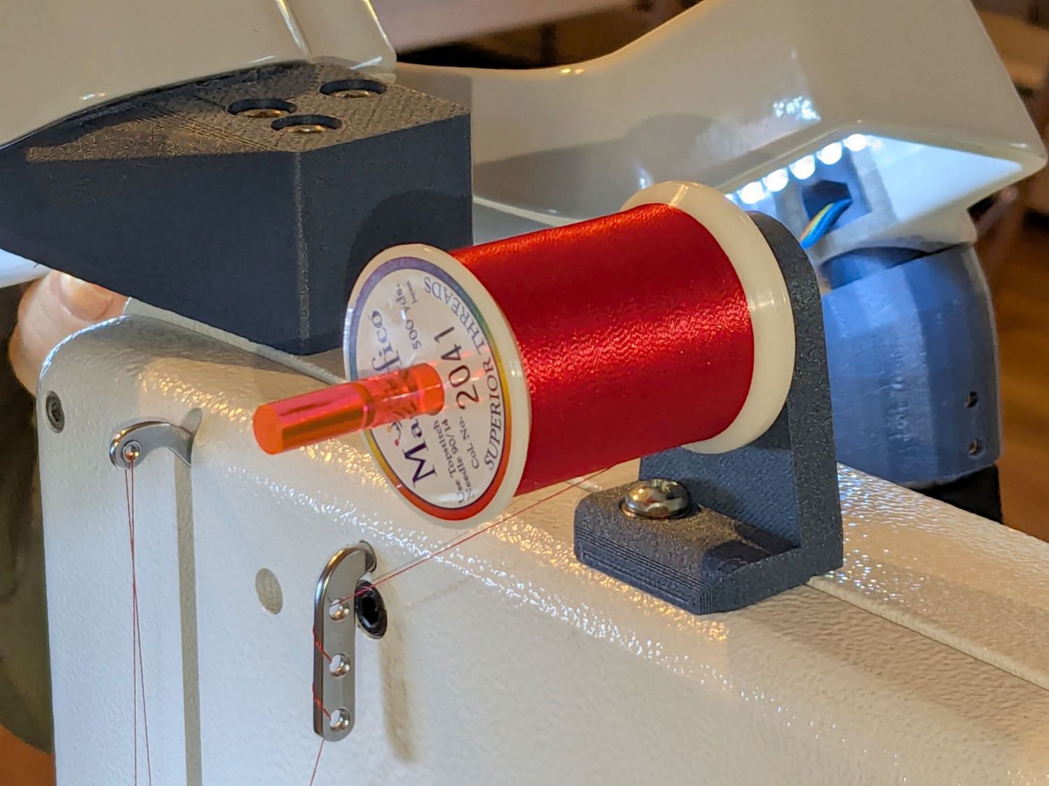
Mary wanted a horizontal spool adapter mounted closer to the front of her HQ Sixteen, in the M5 threaded hole where the Official Horizontal Adapter would go:
HQ Sixteen – front spool adapter – installed
Yes, the pin through the spool is fluorescent edge-lit orange acrylic that looks wonderful in sunlight and is much more amusing than the black rod in the adapter atop the power supply pod.
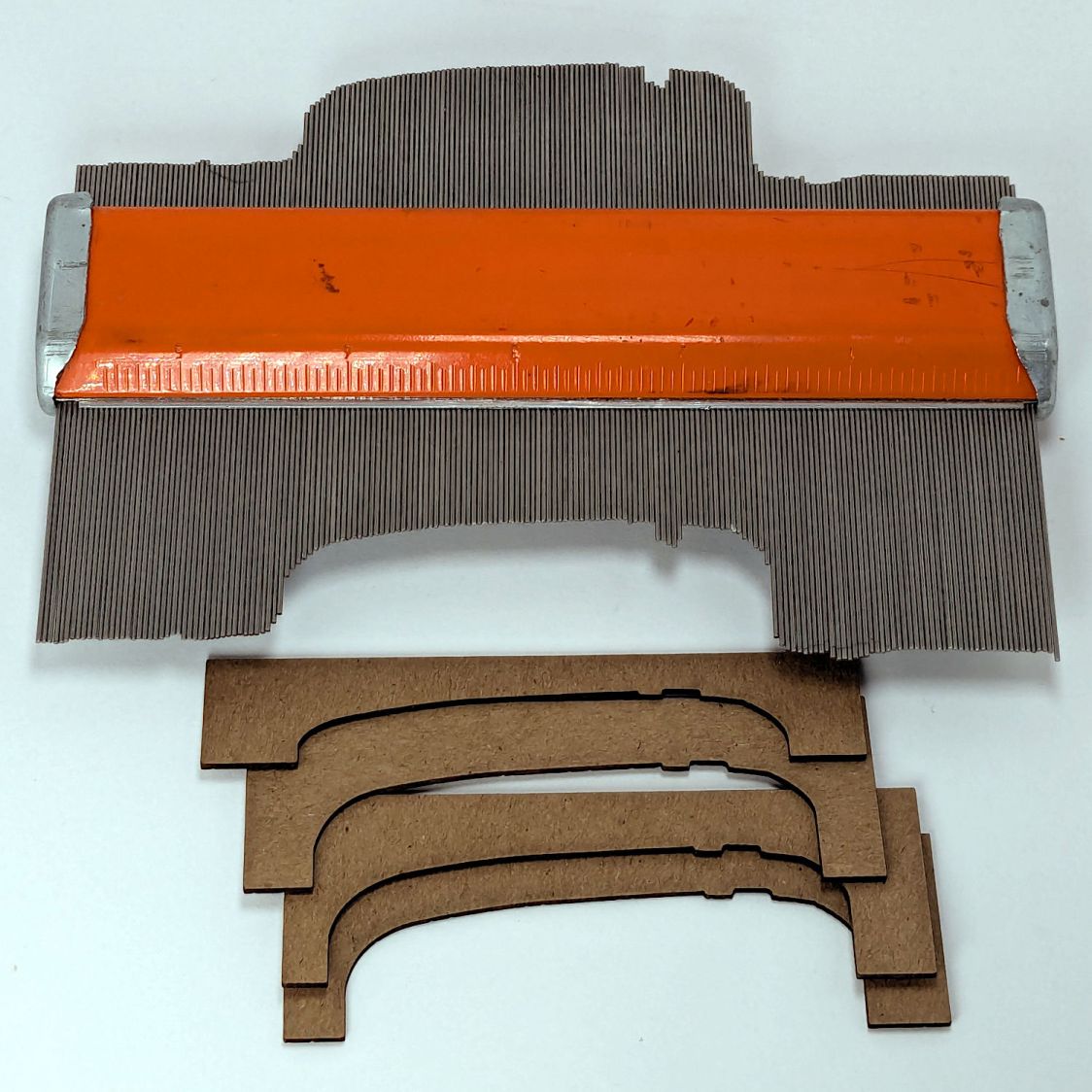
The top of the machine case is not flat, level, or easy to model, so I deployed the contour gauge again, with some attention to keeping the edge pins parallel & snug along the machine sides:
HQ Sixteen – machine profile measurement
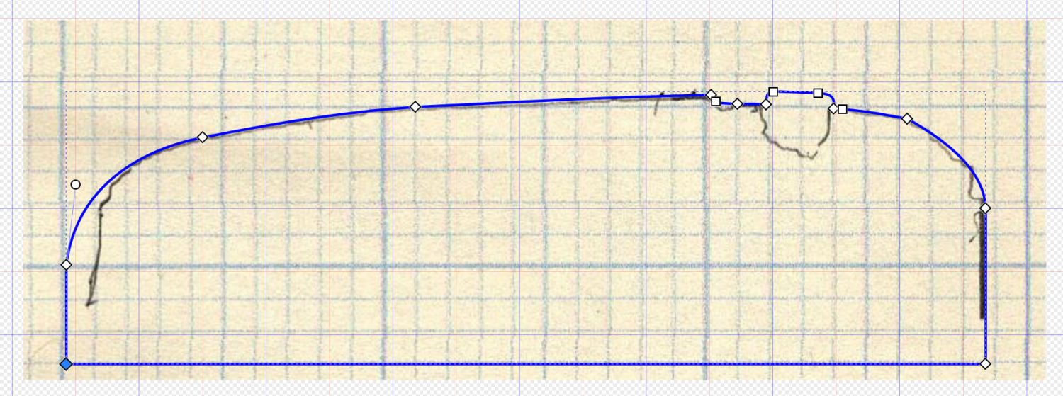
Tracing the edge of the pins onto paper, scanning, and feeding it into Inkscape let me lay a few curves:
HQ Sixteen – top profile curve – Inkscape fitting
The laser-cut chipboard test pieces show the iterations producing closer and closer fits to the machine.
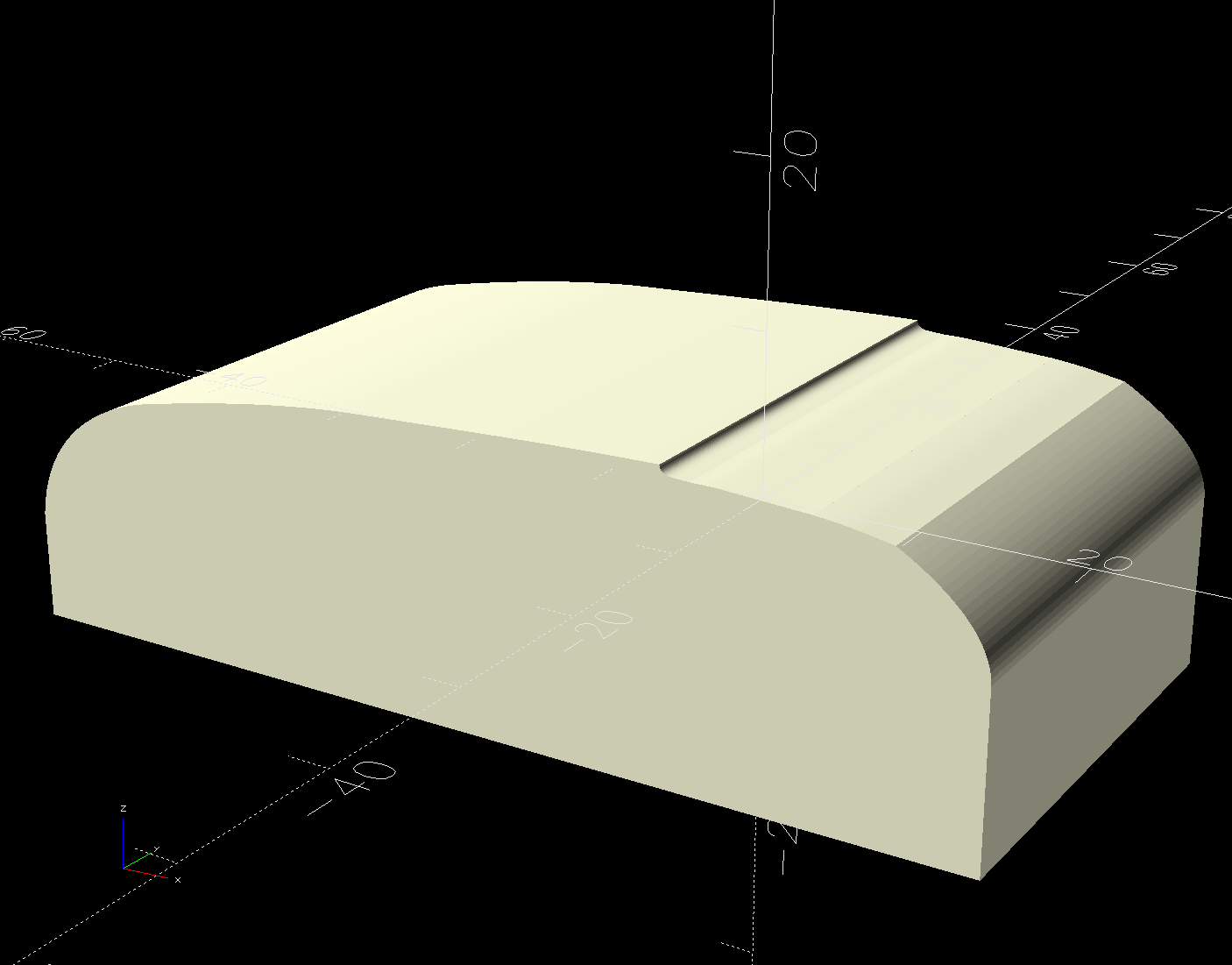
Importing the final SVG image into OpenSCAD and extruding it produced a suitable solid model of the machine’s case:
HQ Sixteen – machine solid model
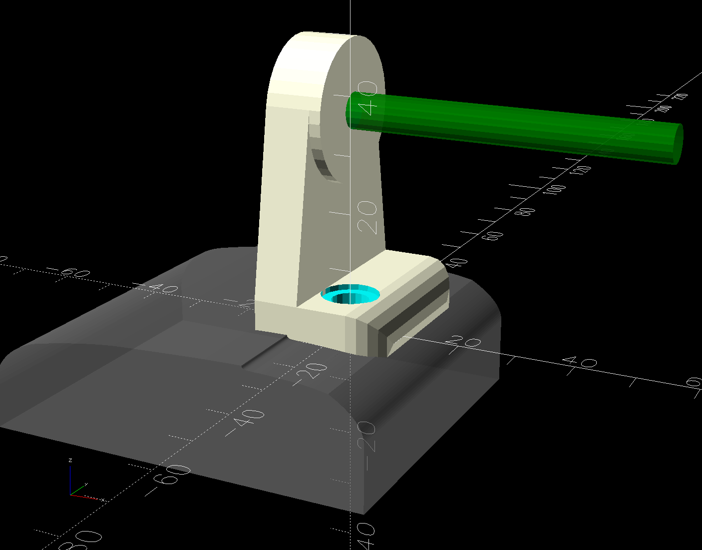
Subtract that shape from the bottom of the adapter to get a perfect fit atop the machine:
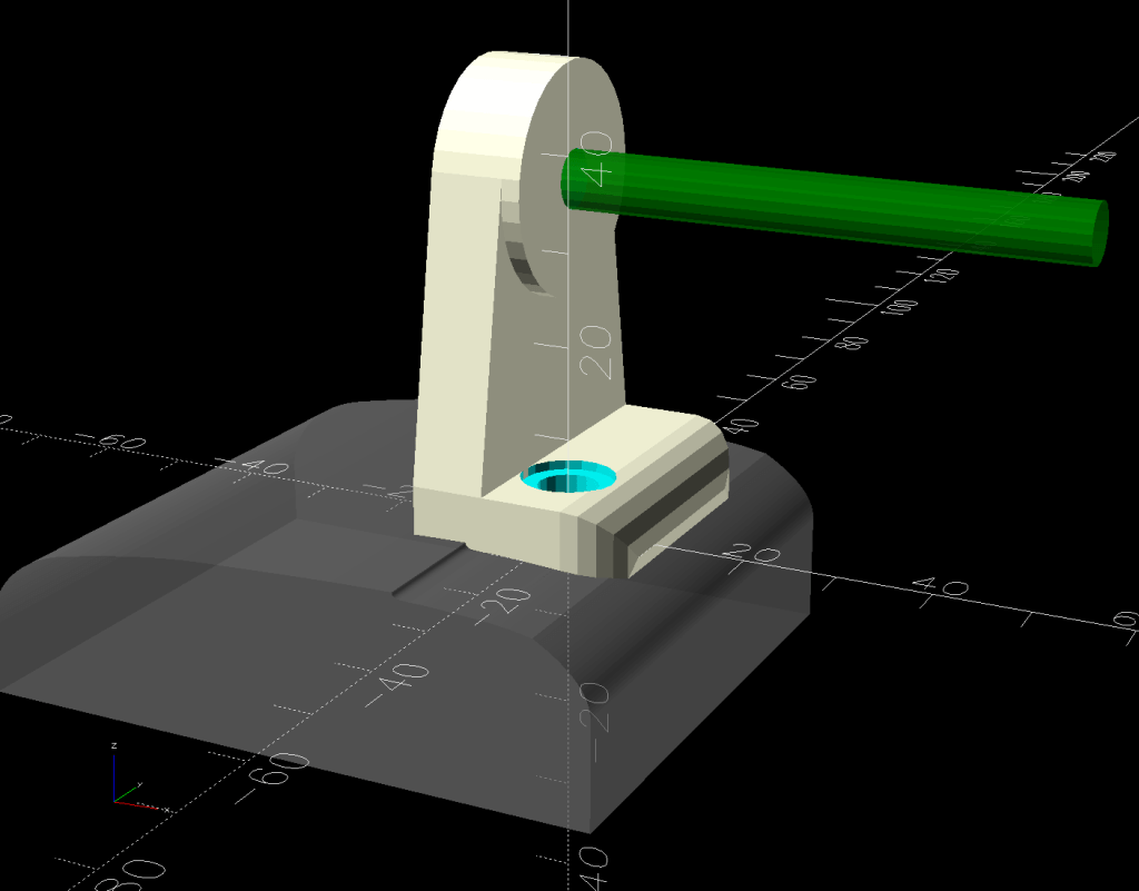
HQ Sixteen – horizontal thread spool adapter – front pin – solid model – show
Early results are encouraging, although the cheap polyester thread Mary got from a friend’s pile and is using for practice untwists itself after passing through the tension disks on its way to the needle. She’ll load much better thread for the real quilt.
The OpenSCAD source code and SVG of the HQ Sixteen’s top profile as a GitHub Gist:
This file contains hidden or bidirectional Unicode text that may be interpreted or compiled differently than what appears below. To review, open the file in an editor that reveals hidden Unicode characters.
Learn more about bidirectional Unicode characters
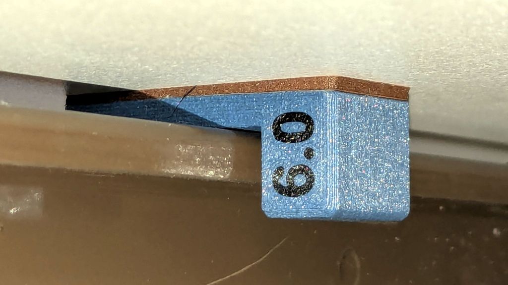
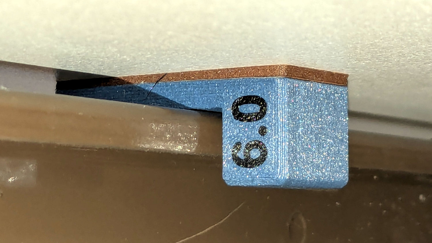
The HQ Sixteen has been running at higher speeds as Mary practices using its stitch regulator and the vibrations shook several of the table shims (blocks, whatever) onto the floor. I hope a layer of EVA foam provides enough compliance to keep them in place:
HQ Sixteen – padded table shim – installed
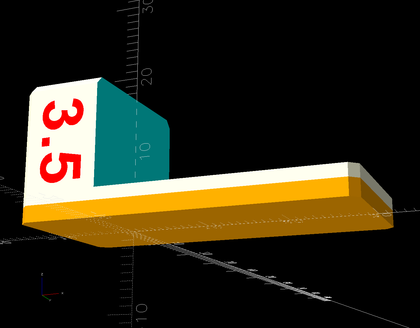
The foam is 2 mm thick, so subtracting that from the nominal thickness makes the new blocks come out right.
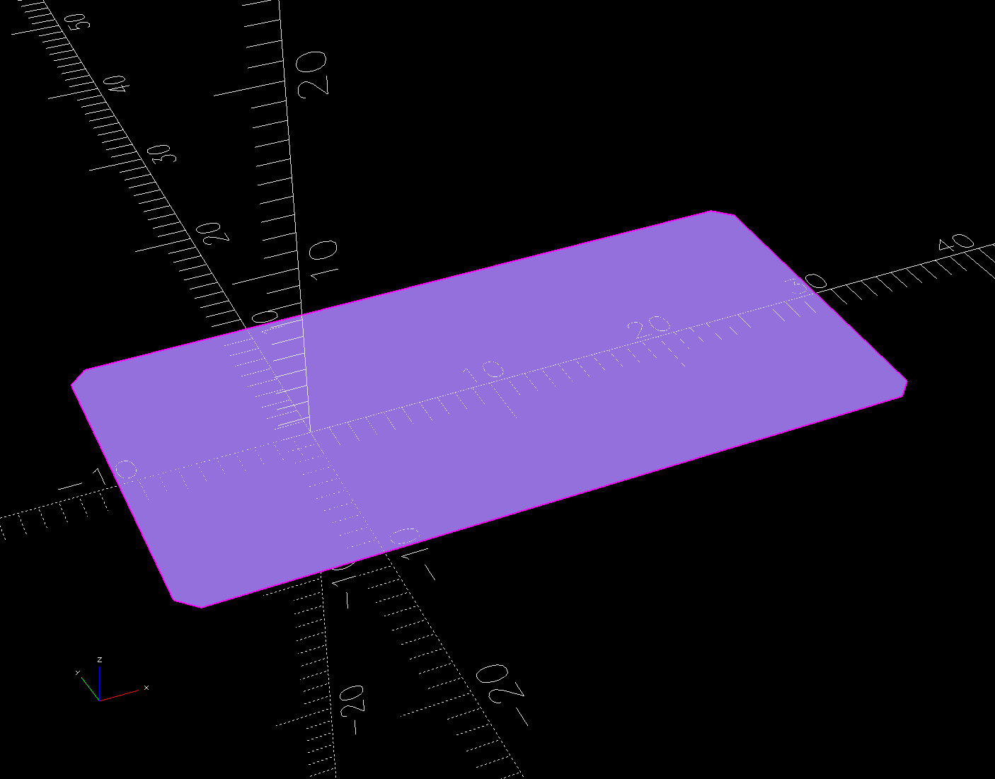
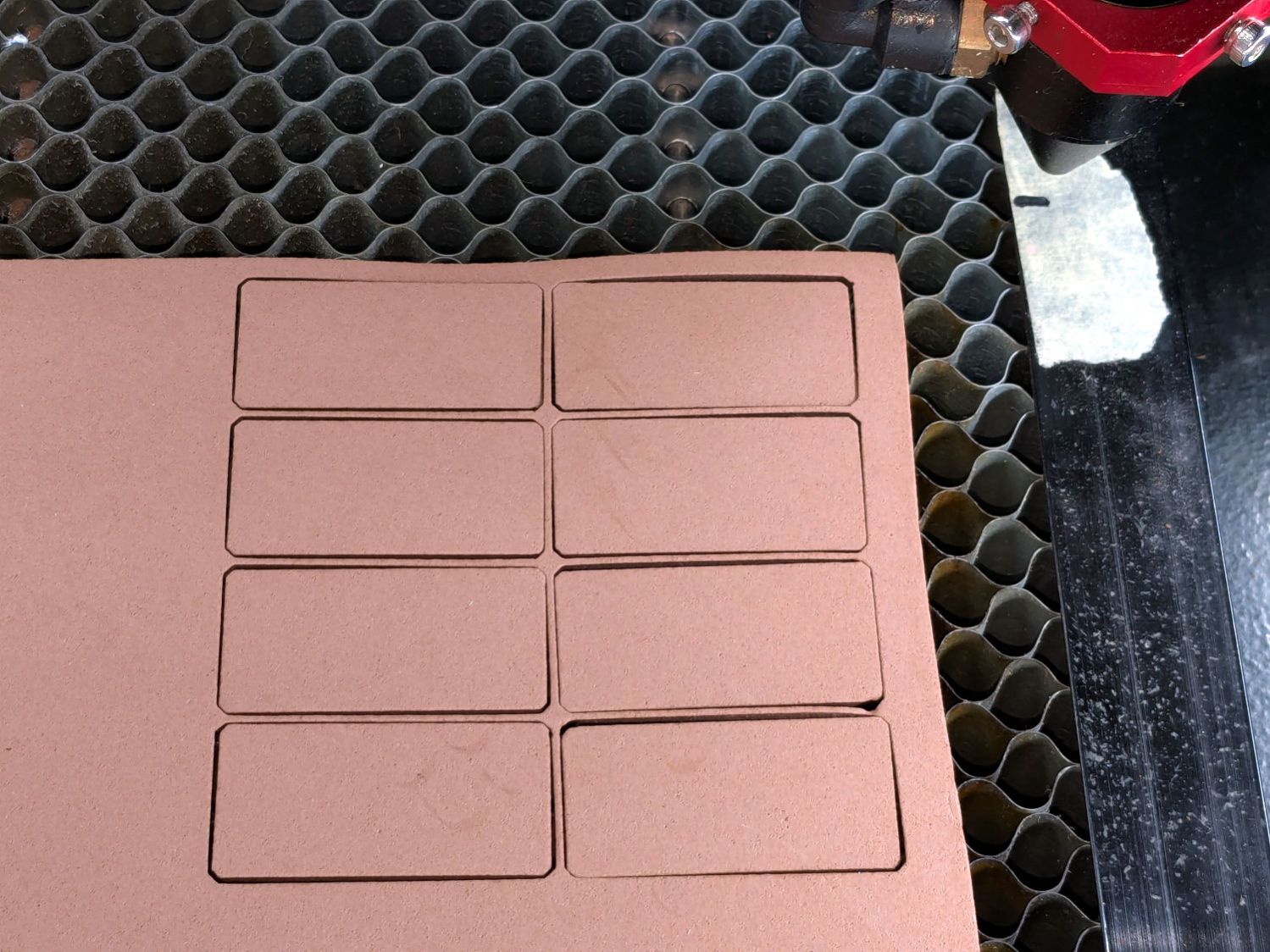
A short module extracts the footprint for export as an SVG image to laser-cut both the foam and the adhesive sheet required to stick it in place:
Trace the outlines and lay smooth curves around them with Inkscape:
Remote profiles – Inkscape curves
They needed a slight lengthening to account for the gauge pin diameter & deflection, but this isn’t a precision project.
Do the same with a scan of the front face, import the curves into OpenSCAD, extrude them, create a solid model of the remote from their mutual intersection, then add a cylinder to punch the depression for the steel plate:
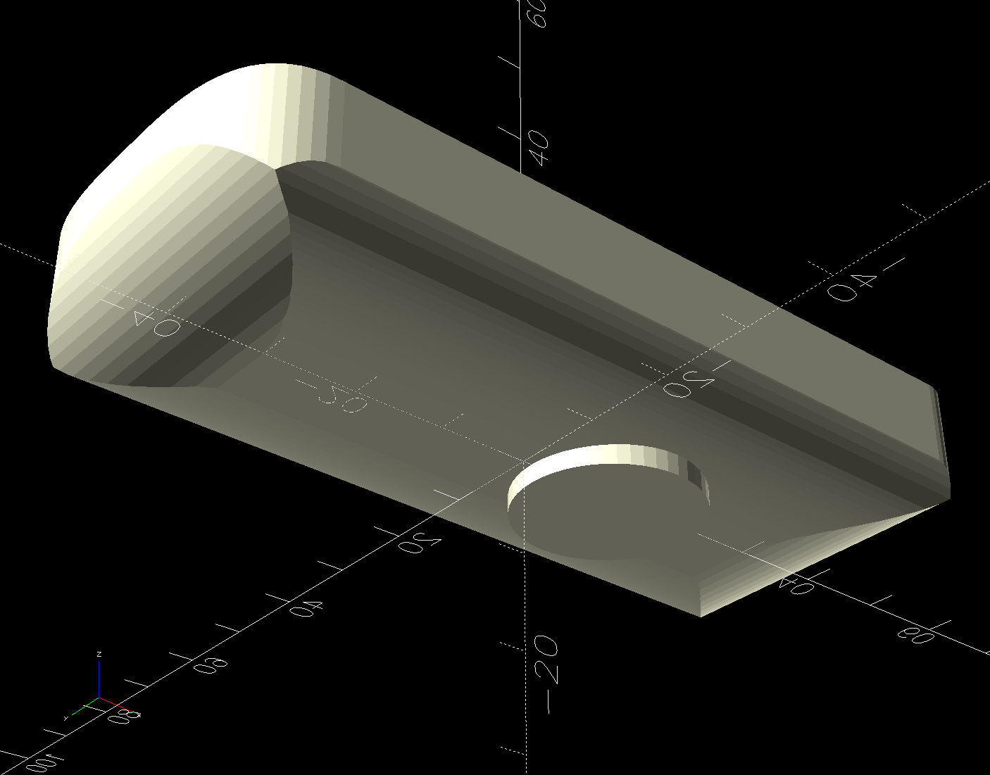
Floor Lamp Remote Holder – solid model – bottom
The chonky model corners stick out too far compared to the stylin’ curves on the real remote, but I made the holder shorter than the remote specifically to avoid fussing with such details.
Floor Lamp Remote Holder – solid model – Show view
I briefly considered a circumferential clamp around the pipe before coming to my senses and making the pipe diameter 2 mm larger to accommodate a strip of double-sided foam tape.
The magnet gets a ferocious grip on the plate and I defined the result to be All Good™.
The OpenSCAD source code and SVG paths as a GitHub Gist:
This file contains hidden or bidirectional Unicode text that may be interpreted or compiled differently than what appears below. To review, open the file in an editor that reveals hidden Unicode characters.
Learn more about bidirectional Unicode characters
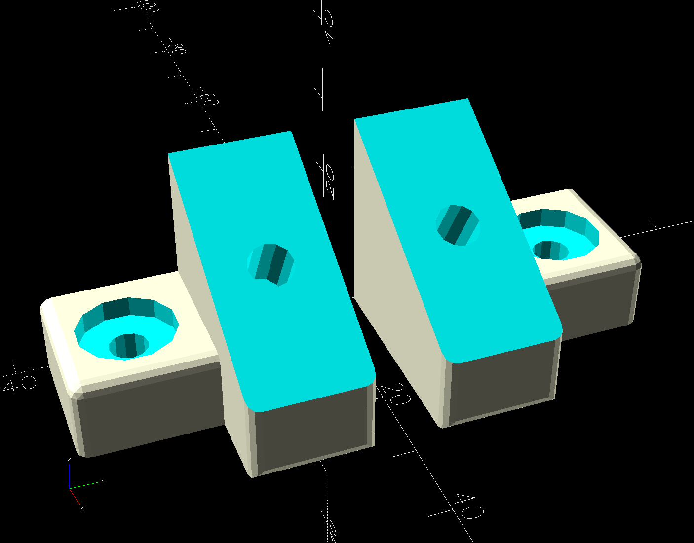
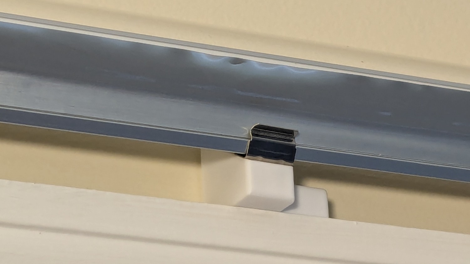
The object of the game being to tilt the LED strip lights at (maybe) 30° to put more light higher on the wall and further out on the ceiling, with the overriding constraint of no visible holes. Given their eventual home atop the window moulding along the front wall of the Living Sewing Room, these seemed adequate:
LED Bar Lamp Mount – solid model
The hole on the angled part fits an M4 brass insert and the recessed holes capture the washer-like head of a sharp-point lath screw.
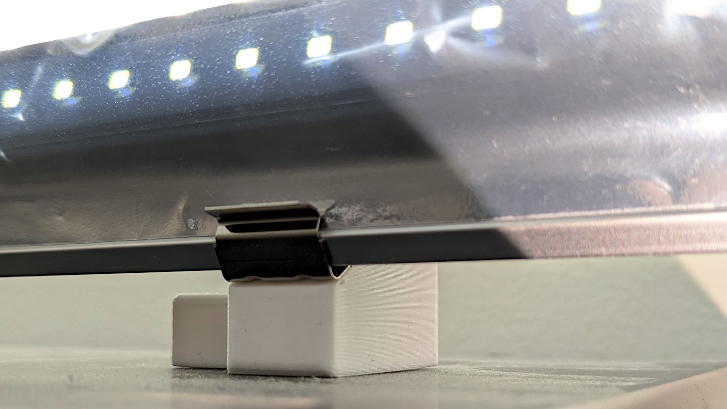
Two pairs applied to the lights sitting atop the Fabric Cabinets served to verify the fit:
LED strip light – moulding mount – on cabinet
They’re held firmly by the aluminum extrusion and don’t need a bigger footprint to remain stable.
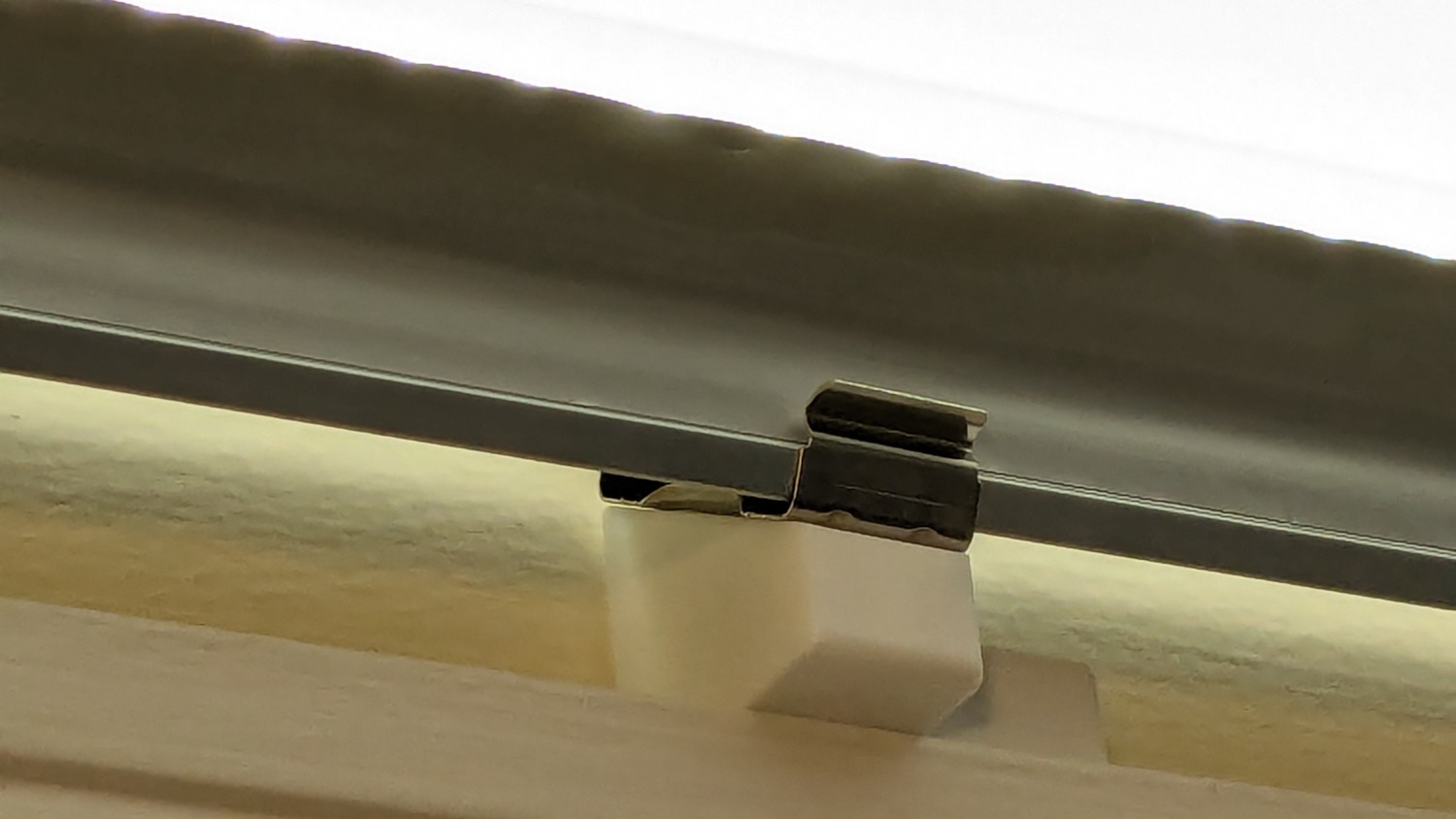
So I made another six, stuck on ⅞ inch strips of aluminized Mylar (cut from a bag in much better condition), and drilled holes where they can’t be seen:
LED strip light – moulding mount – installed
It’s almost too bright in there with 3 × 40 W of LED lights washing the wall and ceiling:
LED strip light – moulding mount – lit
I don’t like the cold 6000 K color temperature, but Mary doesn’t mind it. They fill the Sewing Table with shadowless / glareless light, although that kind of light makes the place look like a store.
I think moving the strip lower and away from the wall could hide the entire mount from view.
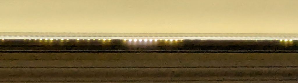
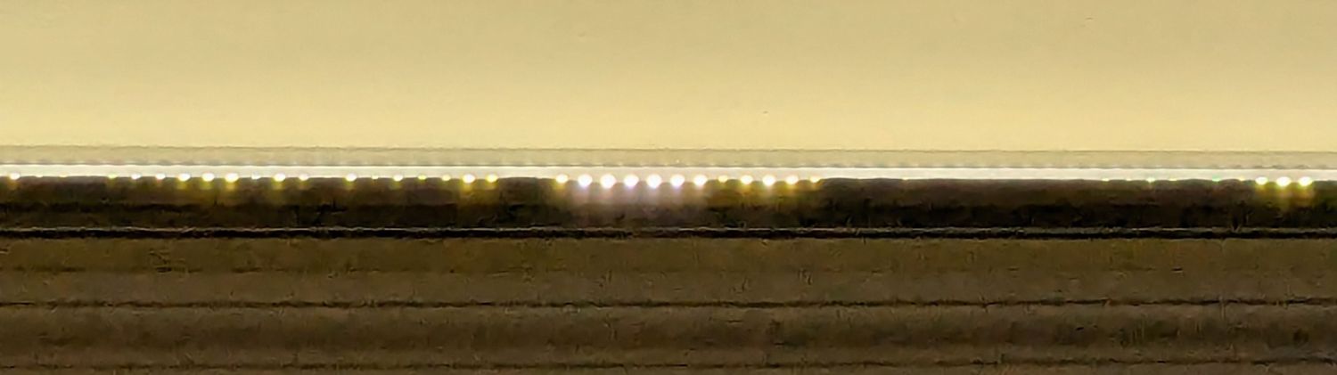
Contrary to what I expected, the Mylar reflectors must be at least an inch tall to avoid Baily’s Beads seen from across the room:
LED strip light – short reflector
With all that in mind, we’ll run these for a while to shake out any other improvements.
This file contains hidden or bidirectional Unicode text that may be interpreted or compiled differently than what appears below. To review, open the file in an editor that reveals hidden Unicode characters.
Learn more about bidirectional Unicode characters
The L4-L5 pair are part of an extensive human anatomic model locating all the pieces at their proper coordinates, so these two hovered about 800 mm above the XY plane. I ran them through the Grid:Tool mesh editor to center them at the XY origin, then put the bottom-most point at Z=0.
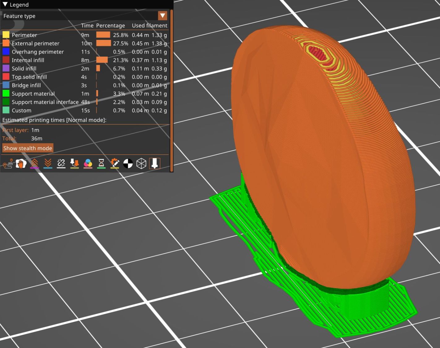
Rotating them individually in PrusaSlicer and painting only the most essential support got them to this state:
L4 L5 vertebrae – PrusaSlicer
Each one take about three hours, so I ran them individually to reduce surface blemishes and maximize the likelihood of happy outcomes. Worked like a champ.
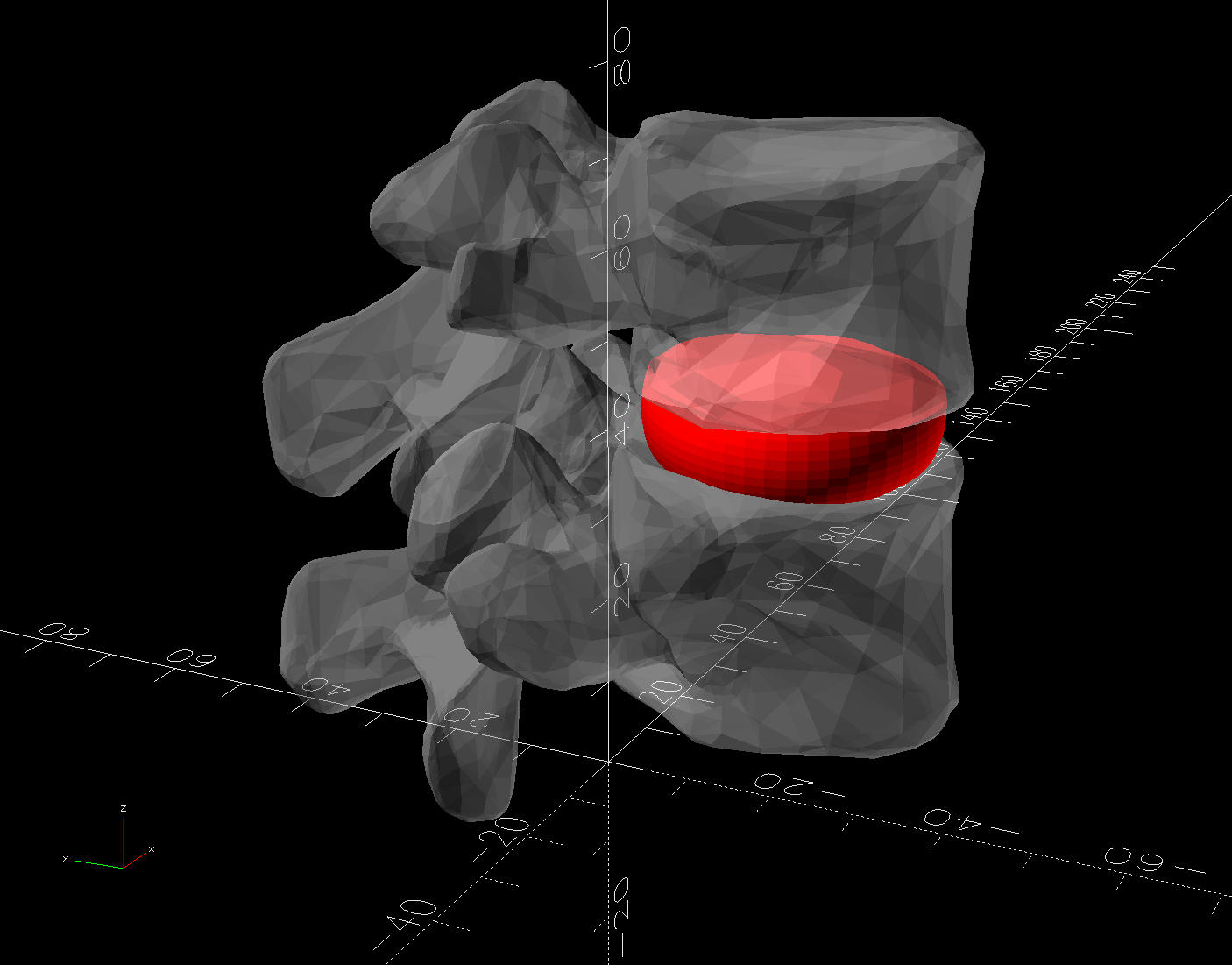
The retina-burn orange disk is not anatomically correct, because the InterWebz apparently does not have a model for spinal cartilage:
L4 L5 vertebrae – assembled – disk detail
Instead, it’s a rounded cylinder resized into an oval, with its top and bottom surfaces formed by subtracting the vertebrae:
L4 L5 vertebrae disk – solid model
The OpenSCAD code doing the heavy lifting:
// Disk between L4 and L5 vertebrae
// Ed Nisley - KE4ZNU
// 2025-03-07
Layout = "Show"; // [Show,Build]
include <BOSL2/std.scad>
module Disk() {
color("Red")
difference() {
translate([9,-18,36])
rotate(110)
resize([33,45])
cyl(d=50,h=14,$fn=48,rounding=7,anchor=BOTTOM);
import("../Spine/human-spinal-column-including-cervical-thoracic-and-lumbar-vertebra-model_files/L4 L5 vertebrae stacked.stl",
convexity=10);
}
}
if (Layout == "Show") {
Disk();
color("White",0.3)
import("../Spine/human-spinal-column-including-cervical-thoracic-and-lumbar-vertebra-model_files/L4 L5 vertebrae stacked.stl",
convexity=10);
}
if (Layout == "Build") {
Disk();
}
All of the magic numbers come from eyeballometric measurement & successive approximation.
The Build layout left the disk floating in space, whereupon I used PrusaSlicer to reorient it edge-downward on the platform with painted-on support for minimal distortion:
L4 L5 vertebrae disk – PrusaSlicer
Two dots of E6000+ adhesive hold everything together.
All in all, it was a useful distraction. I’ve been vertically polarized for the last five days and it’s good to be … back.
Although the images are algorithmically generated in a common layout, figuring out how to get the outlines as paths seemed to require a journey into the depths of the Pygame library and that would turn into a major digression.
Instead, start with one of the webp images:
sq_RGBY
The deliberate blurring apparently simulates what you see in real life.
Import the image into LightBurn, which converts it to grayscale under the plausible assumption you’re going to engrave the image on something. Then:
Create a rounded rectangle overlaying the lower-left-most subpixel to good eyeballometric accuracy
Turn it into a four-element rectangular array, twiddling the center-to-center spacing to match the subpixel layout
Duplicate those four upward in another array to create a subpixel block, as marked in the upper-left corner of the original image
Slam another array across the bottom row and upward, twiddling the spacing to match the subpixel block spacing along both axes
Which eventually looks like this:
SubPixels – LightBurn vector overlay
I made the final array absurdly large, cropped it with a square to match the template I used for the layered paper patterns, resized the result to be 170 mm on a side, then dropped the square into the middle of the template:
Subpixel Zoo – Quattron RGBY – LightBurn black mask layer
One gotcha: crop the subpixels on a Fill layer so LightBurn will close the truncated edges, then put them on a Line layer for cutting. The doc explains why, although it’s not obvious at first, as is the fact that you must delete the group of shapes outside the square before it looks like anything happened during the cut operation.
The resulting layout contains all the subpixel rectangles, so it’s what you want for the top black mask layer. Duplicate the pattern and delete the subpixels corresponding to each color, until you have one template for each of the Red / Green / Blue layers:
Subpixel Zoo – Quattron RGBY – LightBurn layers
The blank over on the right is the Yellow layer, which does get a quartet of layer ID holes cut in the lower right corner.
Then it’s just a matter of cutting the blanks, locating the fixture on the platform, dropping the appropriate color sheet in place, cutting it, then assembling the stack in the gluing fixture:
Subpixel Zoo – Quattron RGBY
It’s kinda cute, in a techie way.
I did a bunch of layouts, just to see what they looked like:
Subpixel Zoo – 8×8 layouts
In person, the RGBY patterns look bright and the RGB patterns seem dull by comparison. I’m using cardstock paper, rather than fancy art paper, which surely makes all the difference.