
The Ruida KT332N controller on my OMTech laser cutter has two settings affecting the final position of the U axis (which controls the platform’s position) after pushing the Focus button on the machine console:
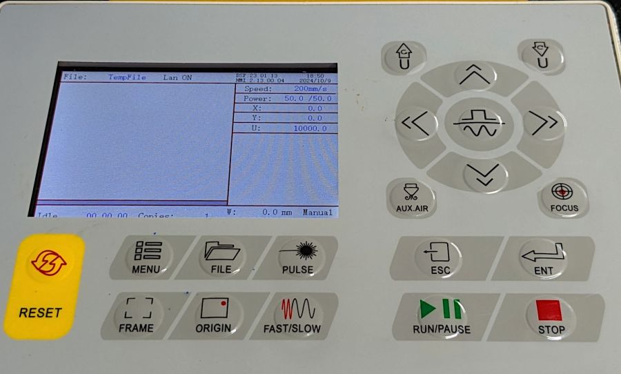
After turning the machine on or pressing the Reset button, the U axis does not automatically home and reports its position as 1000 mm. This allows manual control in either direction with the U↑ and U↓ buttons.
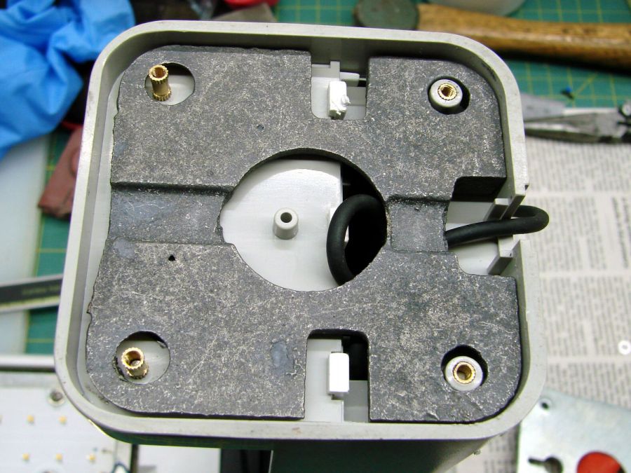
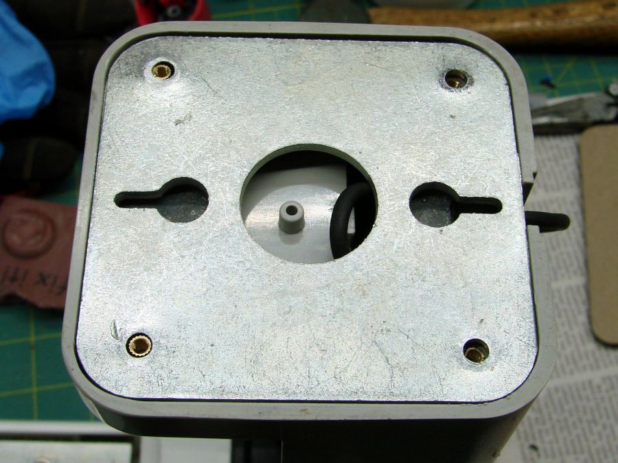
Pushing the Focus button (then confirming the action by pressing the Ent⏎ button) causes the controller to raise the platform until the focus “pen” (which is really a switch) trips, presumably on the material you intend to cut / engrave. This picture shows the pen and its attachment to the laser nozzle:
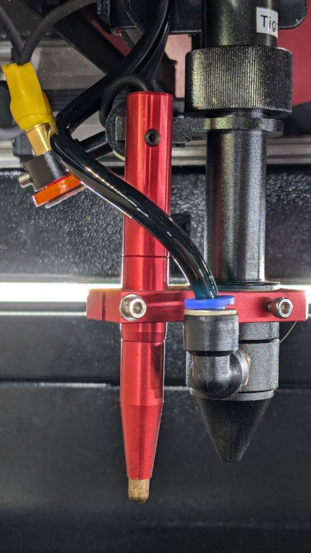
The pen’s position in its clamp has no relation to the laser beam focal point below the nozzle: loosening either of the clamp screws lets you move the pen vertically. You must tell the controller how much to move the platform after the switch trips to properly set the focus, which means you must measure that distance. More on that later.
The vertical position of the platform when the “pen” switch trips is its Home position. The controller then lowers the platform by the distance in the Home Offset setting and defines that position as U = 0.0 mm.
The Home Offset can be zero:

In which case the platform does not move after the switch trips:
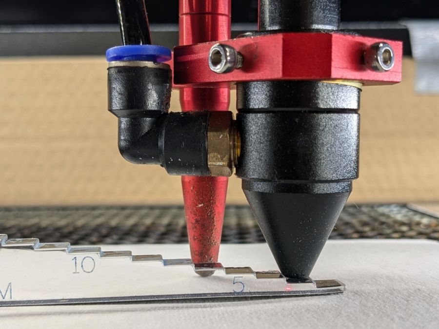
The step gauge shows the nozzle is 3.0 mm above the material (the first step is 2 mm, because a 1 mm acrylic tab is crazy talk) when the switch trips. Although you can’t quite see the switch plunger through the gauge, it has about 5 mm of travel before tripping, which means it’s firmly pressed against the material and you must not move the nozzle in X or Y to avoid scraping the plunger across the material.
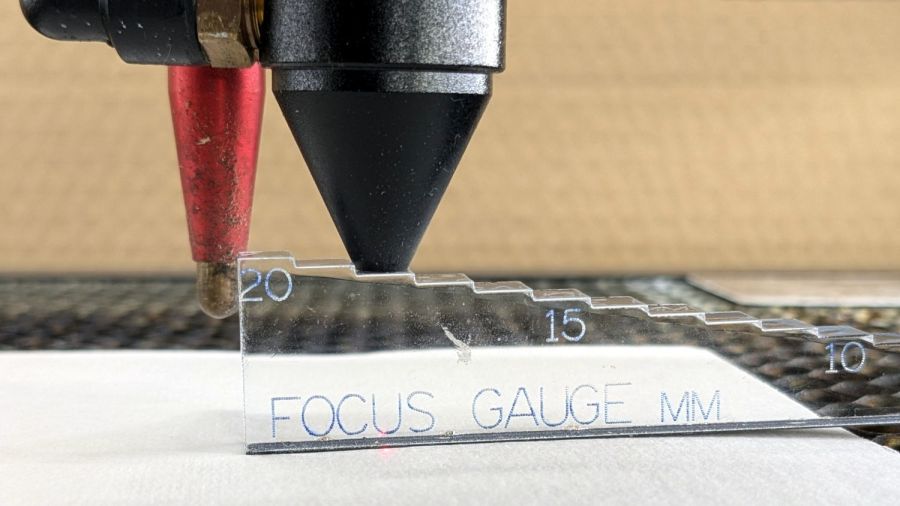
Setting Home Offset to 15.0 mm lowers the platform by 15 mm after the switch trips, putting the nozzle 18 mm above the material:
You can (and I have) set the Home Offset so the platform lowers by exactly enough to put the focused beam at the top of the material: push the Focus button and the machine automatically focuses on the material and sets U=0.0 mm at that level.
Unfortunately, the controller will subsequently not move the platform above that position, corresponding to U axis coordinates below zero. That means you (well, I) cannot move the platform upward to put the focus point into the material, as is sometimes required for a good cut through thicker material.
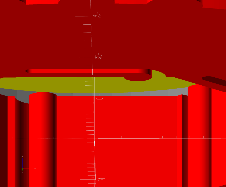
The Focus Distance setting defines an additional distance from wherever the Home Offset leaves the platform:

It’s not 15 mm, because I was fiddling with the focus.
That value will position the platform 16 mm below the switch trip point. Because Home Offset = 0.0 sets the U axis coordinate to zero at the trip point, the U axis will be at 16 mm when the platform stops moving.
The key difference is that the controller will now allow the platform to move upward, with decreasing U axis coordinates, until it reaches the switch trip position at U=0. The last 5 mm of travel will occur with the switch actuator pressing against the material, so it’s pretty much useless for actual cutting or engraving.
So I think the way to go involves setting:
Home Offsetto the 5-ish mm required for full switch releaseFocus Distanceto the remaining 10-ish mm with the focal point on the material surface
I hadn’t done that before, because I hadn’t thought this through.
The Home Offset depends only on the switch travel before it actuates and won’t change when (not if) the pen position changes with respect to the nozzle.
The Focus Distance defines the additional travel for proper focus at the material surface, so that’s where all the variations due to pen position will go. Unfortunately, that distance cannot be directly measured, because it corresponds to the difference between two positions.
Today I Learned, etc.


