Ed Nisley's Blog: Shop notes, electronics, firmware, machinery, 3D printing, laser cuttery, and curiosities. Contents: 100% human thinking, 0% AI slop.
Category: Science
If you measure something often enough, it becomes science
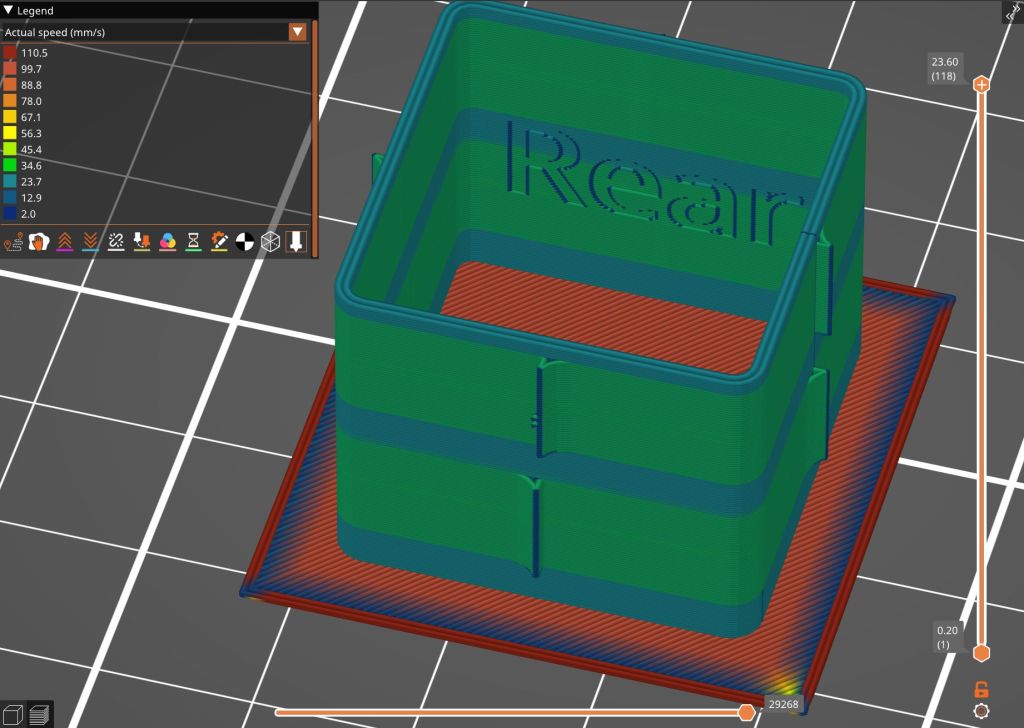
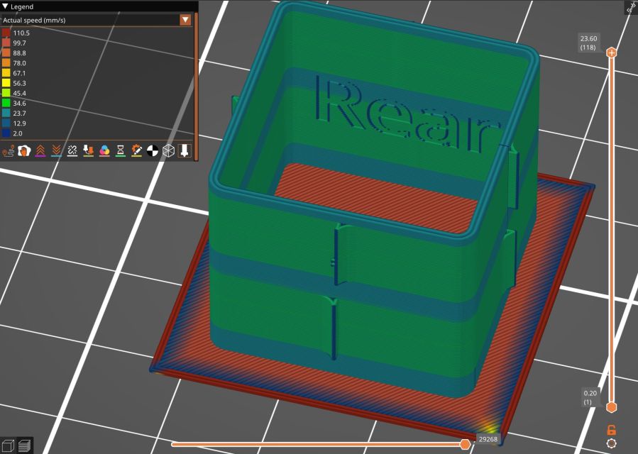
Loading the STL into PrusaSlicer, adding a text label to remind me which way it printed, then slicing with my PETG-CF profile shows the “Actual Speed”, which seems to take acceleration into consideration:
PrusaSlicer preview – actual speed
The colors in the legend don’t quite match the colors on the model, but the greenish layers with the jolts trundle along in the mid-20 mm/s range and the blue-ish straight-through layers at 30-ish mm/s.
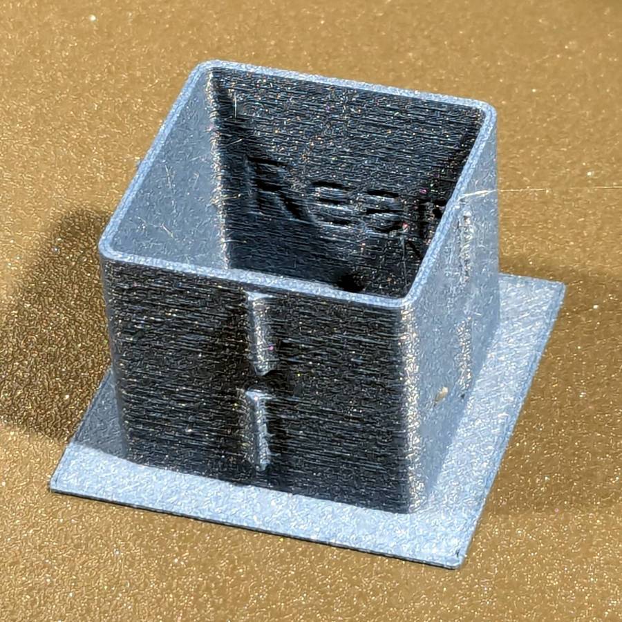
Eryone PETG-CF has a somewhat fuzzy appearance that seems not characteristic of other brands, so I’ll try something else when these spools run out:
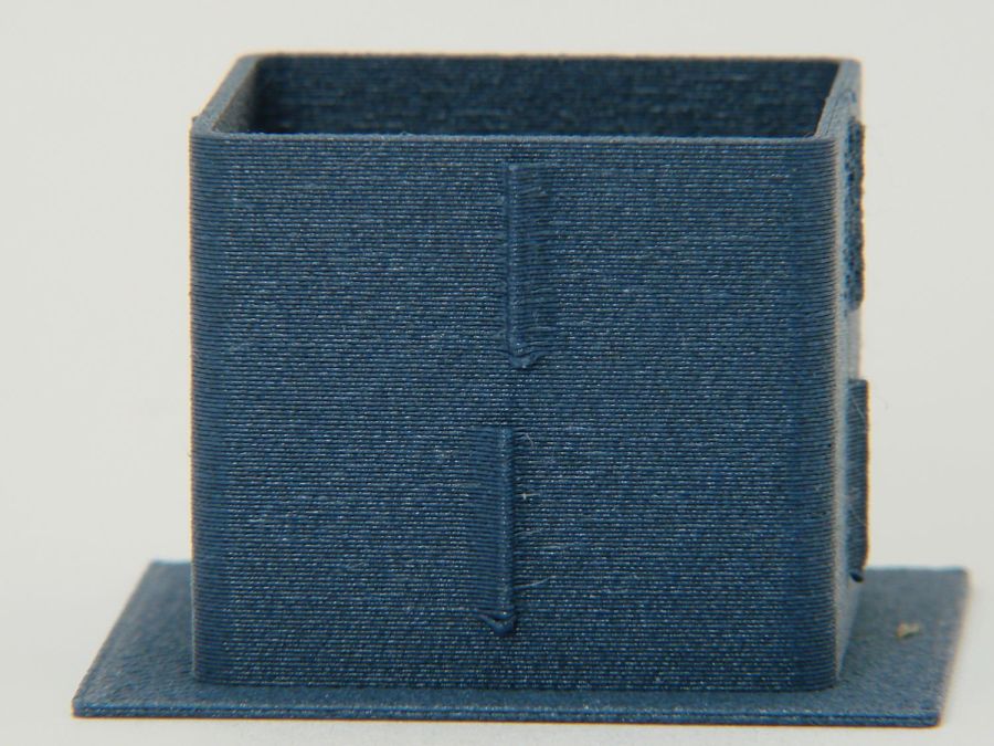
MK4 Resonance Test Box – overview
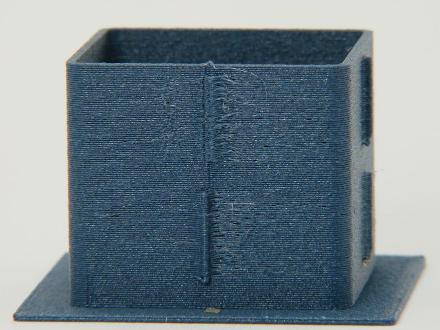
The right side of the box (as oriented on the platform) got all the layer retractions and came out festooned with PETG hairs:
MK4 Resonance Test Box – right side
You can check my labels by tracking the small retraction zit sticking up from the top layer; I got it wrong the first time. Open the images in a new tab to see more pixels.
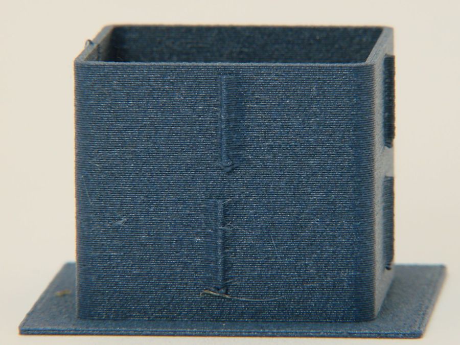
The front:
MK4 Resonance Test Box – front side
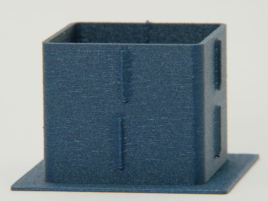
The left:
MK4 Resonance Test Box – left side
And the rear:
MK4 Resonance Test Box – rear side
You can barely see the shadow of the “Rear” text on the surface, even though the wall is two threads thick and the text is indented by 0.2 mm, about half the thread width.
As far as I can tell, the MK4 Input Shaper compensation does a great job of suppressing resonance or wobble in all directions.
The Prusa belt tension guide pretty much explains that subject, with their Belt Tuner making up for my utter tone deafness. FWIW, if the Belt Tuner produces inconsistent results differing by an octave, either up or down from the correct value, the belt is way too loose: give the axis belt tension screw a turn or two to drag the results into the right time zone, then fine-tune from there.
While it is possible to reach both tensioning screws without too much trouble, they’re definitely not convenient.
The accelerometer fits on the hot end:
Prusa MK4 Accelerometer – on hot end
Then under the steel sheet, where it’s clamped by the platform magnets:
Prusa MK4 Accelerometer – on platform
The MK4 firmware measures the resonant frequencies while prompting you to put the accelerometer in the proper locations, then computes the best shaper values.
For reference, the stock OEM values:
X = MZV 50 Hz
Y = MZV 40 Hz
Just after I got the accelerometer and without doing anything to prep the MK4, these results popped out:
X = MZV 56 Hz
Y = MZV 42 Hz
Now, with bling and properly tensioned belts:
X = MZV 59 Hz
Y = MZV 45 Hz
The most recent values were also the most stable, once again pointing out the value of careful assembly and maintenance.
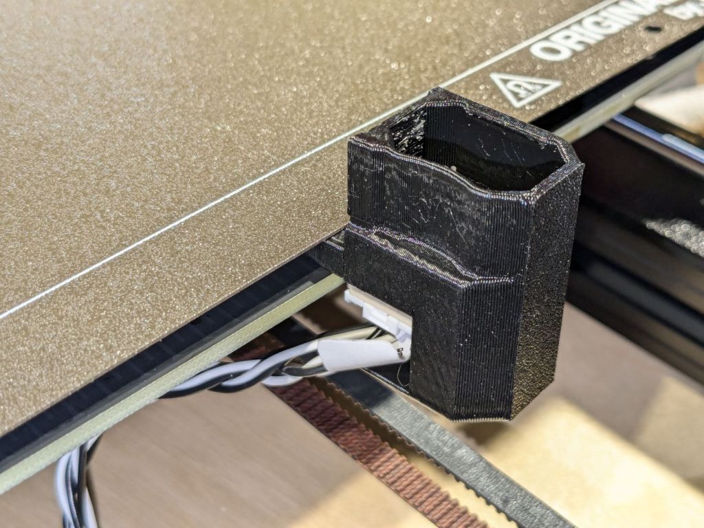
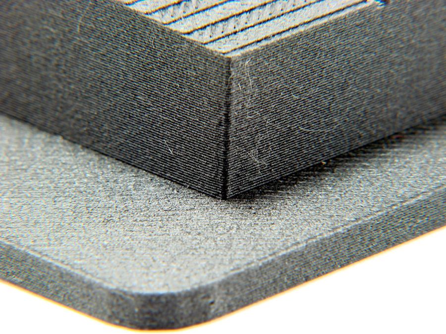
With that in mind, though, I built the laser ramp focus fixture shortly after doing the first recalibration and it has no visible ripples on any of its walls:
Ramp Test Fixture – corner detail
That’s a square corner perpendicular to the sloped top surface at the default 45 mm/s. It’s not as difficult a test as some you’ll see, but it suffices for my simple needs. The MK4 definitely behaves better around corners than the Makergear M2.
Here’s what I think is going on, referring to the 4×8 foot (!) machine in that discussion and lightly edited to improve readability & fix minor errors …
Mirror 1 alignment gets the beam parallel to the Y axis, averaged over the gantry travel between front and rear. The path length variation on your machine is four feet.
Mirror 2 alignment gets the beam parallel to the X axis, averaged over the laser head travel from left to right. The path length variation on your machine is eight feet.
When the laser head is in the left rear corner, the total path length is maybe a foot or two. When it’s in the front right corner, the total path length is upwards of twelve feet.
The “Fourth Corner” problem comes from a slight angular misalignment of Mirror 1, because you (and I and everybody) must set it with a maximum path length around four feet (Mirror 1 to Mirror 2 with the gantry at the front end of the machine). But with the laser head in the right front corner, the path length (Mirror 1 to Mirror 3) is three times longer, so the error due to a slightly mis-set angle at Mirror 1 is correspondingly larger.
A tiny tweak to Mirror 1 changes the spot position at Mirror 2 by very little, but moves the spot at Mirror 3 by much more due to the longer path length.
Tweaking Mirror 1 cannot compensate for a warped machine frame, but it will get the beam alignment as good as it can be made.
The next point of contention was my “middle of the mirror” suggestion. AFAICT, the spot burned into the target at each mirror marks only the useful part of the beam with stray energy in a halo around it. Centering the spot keeps that stray energy away from the mirror mounts, so it doesn’t cause unnecessary heating. This will be particularly important with a high-power laser.
Angular adjustment of each mirror puts the beam parallel to the axes, but cannot also center it on the mirrors. After it’s aligned, the path from the laser tube through the nozzle depends on the position of the tube relative to the nozzle: moving the tube up/down and front/back moves the beam position on the mirrors and through the nozzle, but (in an ideal world) doesn’t change the angular alignment.
So after aligning the beam parallel to the axes, you must move the laser tube, the mirrors (up/down left/right front/back), and maybe the laser head to center the beam in the mirrors and also in the nozzle. Because we don’t live in an ideal world, moving any of those pieces wrecks their angular alignment, so it’s an iterative process.
The goal is to reach this point:
Beam Alignment – Mirror 3 detail – 2023-09-16
Those are five separate pulses, one each at the four corners and center of the platform.
The beam then goes pretty much through the center of the laser head and lens:
Three months of outdoor exposure suggest that laser test paper can survive use as a plant tag for one growing season, at least when it remains flat:
Laser test paper – small plant labels – 3 month exposure
The two upper tags demonstrated the paper has no flexibility worth mentioning, so it cannot become a tag wrapped around a stem.
The two lower labels spent their time tucked into a window frame where they got plenty of sun & rain without the benefit of a backing plate. Looks good to me!
Contrary to my expectation, the craft adhesive sheet behind this label survived intact, although the label itself took some damage, perhaps from the more direct sunlight out on the deck:
Laser test paper – plant marker – 3 month exposure
In any event, they look Good Enough™ for our simple needs and next year’s plants will be properly labeled.
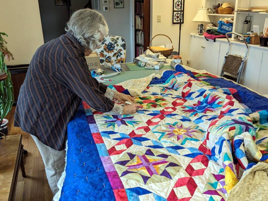
Mary recently finished a multi-year quilt project:
Dancine With The Stars quilt – detail
The overall pattern is “Dancing With The Stars” and it involves more intensive detail work than I have ever deployed on anything I’ve ever done:
Mary with quilt on ping-pong table
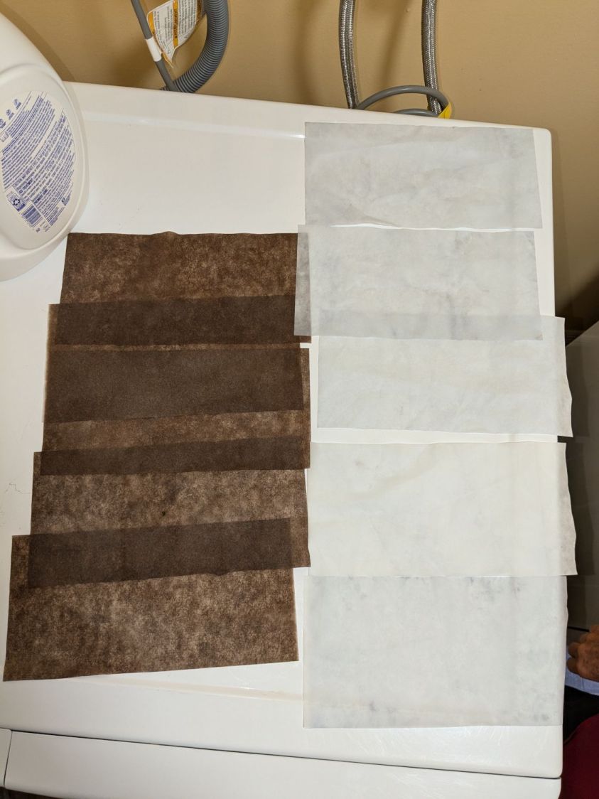
Washing the quilt required a generous handful of Color Catchers to prevent the bold colors from bleeding into the lighter fabrics:
Dancing With The Stars quilt – color catchers
The sheets on the left came from the wash and the ones on the right came from a separate rinse cycle. We didn’t expect the “average” color to be brown, but there it is. We were both mightily relieved when they performed as expected!
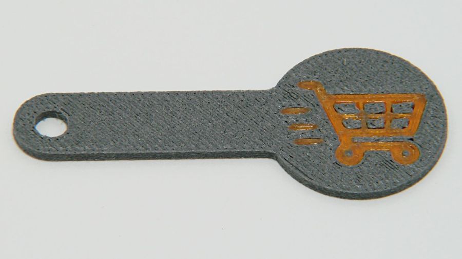
A special request came in for cart coins with a handle:
Overstuffed cart key – 1.0EM
That’s in gray PETG-CF (carbon fiber) with Extrusion Multiplier = 1.0 based on the Pill Tube tests and and slightly lower temperatures based on the temperature tower. It definitely looks overstuffed and so does the Wipe Tower for that set of six coins:
Overstuffed cart key – wipe tower
The orange threads off to the right suggest something went terribly wrong with the top layer, which corresponds to the somewhat recessed cart image in the coin, but there were no other symptoms.
All six of the next set failed completely:
Failed cart key – 1.0EM
Apparently the nozzle hit the clotted gray filament in the Wipe Tower and stalled the X axis motor:
Failed cart key – wipe tower
That suggests the same thing happened to the first set during the last pass over the Wipe Tower, causing a less obvious failure.
Setting the Extrusion Multiplier = 0.65 produced a better result:
Cart key print – blue – 0.65EM
Albeit with a slightly understuffed top layer:
Cart key print – 0.65EM
But not by much:
Cart key print – black – 0.65EM
So the answer depends slightly on the PETG-CF filament color, but not by enough to justify defining three different filament types.
Cart coins are essentially solid plastic layers with no empty infill, so they have nowhere for excess filament to hide. The Wipe Tower should have plenty of room, but even at EM=0.65 the tower looks overstuffed on the side with the carbon fiber purge lines:
Cart key print 0.65EM – wipe towers
The default 110% line spacing in the tower seems too small for PETG-CF, so I’ll increase it to 150% to see if that reduces the clumping.
Judged by the surface finish, a 0.65 Extrusion Multiplier is too low, so I’ll try a set of coins at 0.80.