Ed Nisley's Blog: Shop notes, electronics, firmware, machinery, 3D printing, laser cuttery, and curiosities. Contents: 100% human thinking, 0% AI slop.
Category: Science
If you measure something often enough, it becomes science
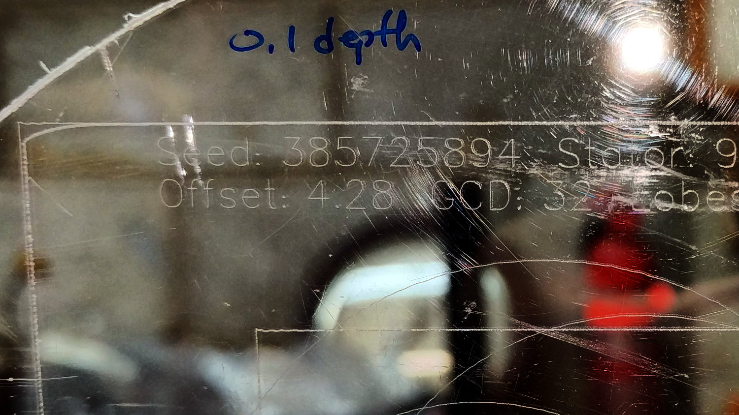
Drawn at Z=-0.1 mm on scrap acrylic with the diamond engraver in the modified collet holder:
MPCNC – Diamond point – acrylic 0.1mm
The badly rounded corner comes from a Z touch off in facepalm mode; the poor diamond must have been trying to dig a 2 mm trench through the acrylic.
Then again at Z=-0.5 mm:
MPCNC – Diamond point – acrylic 0.5mm
At half a millimeter, the holder applies well over 100 g of downforce. There’s no way to know how much lateral force the tip applies to the holder, but it’s obvious the parallel beams on the MPCNC drag knife adapter lack lateral stability:
MPCNC knife adapter mods – OpenSCAD model
Bending beams still seem much better than a linear bearing, though.
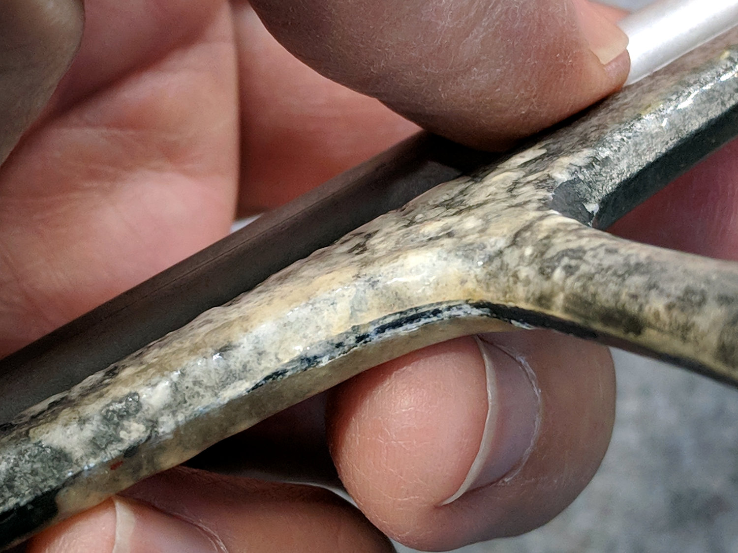
Most of the epoxy remains in good shape, but it’s obviously not the right hammer for this job.
Having recently spotted my tiny sandblaster, I think I can clear off the corrosion and epoxy well enough to try again with good old JB Weld epoxy. It’s not rated for underwater use, so I don’t expect long-term goodness, but it’ll be an interesting comparison.
Bonus: the slicer will start with a uniform gray surface!
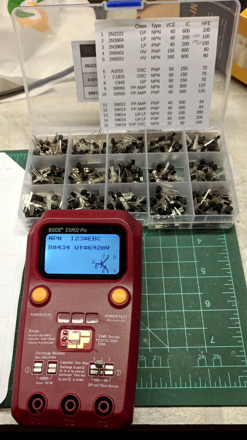
Most of the VBE variation comes from temperature differences: re-measuring the 2N3904 transistors with VBE ≅ 672 mV put them with their compadres at 677 mV.
The 2N3906 transistors have wider gain and VBE variations, so selecting a matched pair for the LM3909 current mirror makes sense.
The sheet inside the lid collects some essential parameters for ease of reference:
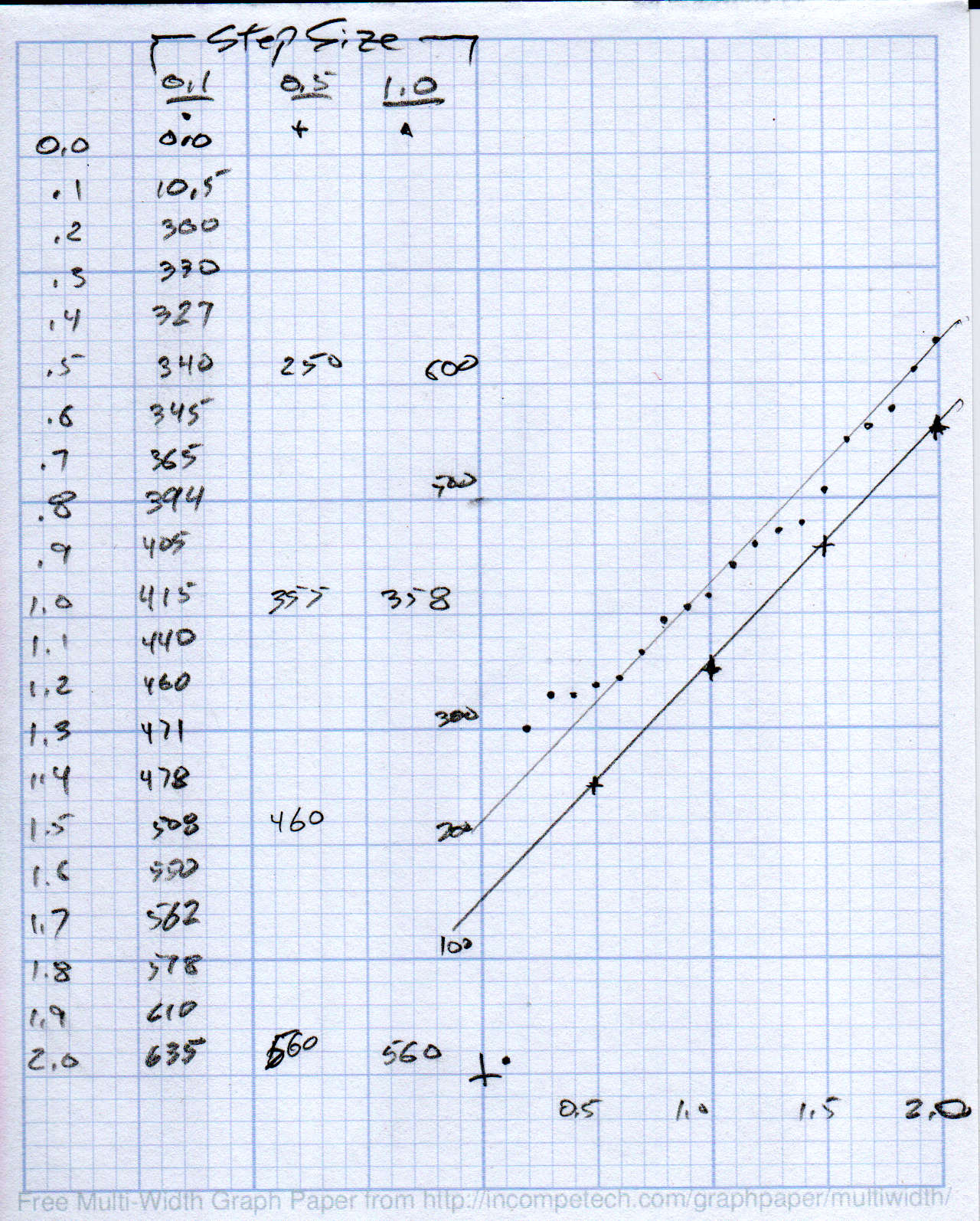
Sliding a drag knife body in a PETG holder, even after boring the plastic to fit, shows plenty of stiction along 2 mm of travel:
MPCNC – Drag Knife Holder – spring constant
Punching the Z axis downward in 0.5 or 1.0 mm steps produced the lower line at 210 g/mm. Dividing by three springs, each one has a 70 g/mm spring constant, which may come in handy later.
The wavy upper line shows the stiction as the Z axis drops in 0.1 mm steps. The line is eyeballometrically fit to be parallel to the “good” line, but it’s obvious you can’t depend on the Z axis value to put a repeatable force on the knife.
I cranked about a turn onto the three screws to preload the springs and ensure the disk with the knife body settles onto the bottom of the holder:
MPCNC – DW660 adapter drag knife holder – spring loaded
The screws are M4×0.7, so one turn should apply about 140 g of preload force to the pen holder. Re-taking a few data points with a 0.5 mm step and more attention to an accurate zero position puts the intercept at 200 g, so the screws may have been slightly tighter than I expected. Close enough, anyway.
The stiction is exquisitely sensitive to the tightness of the two DW660 mount clamp screws (on the black ring), so the orange plastic disk isn’t a rigid body. No surprise there, either.
Loosening the bored slip fit would allow more lateral motion at the tip. Perhaps top-and-bottom Delrin bushings (in a taller mount) would improve the situation? A full-on linear bearing seems excessive, even to me, particularly because I don’t want to bore out a 16 mm shaft for the blade holder.
It’s certainly Good Enough™ as-is for the purpose, as I can set the cut depth to, say, 0.5 mm to apply around 250-ish g of downforce or 1.0 mm for 350-ish g. The key point is having enough Z axis compliance to soak up small table height variations without needing to scan and apply compensation.
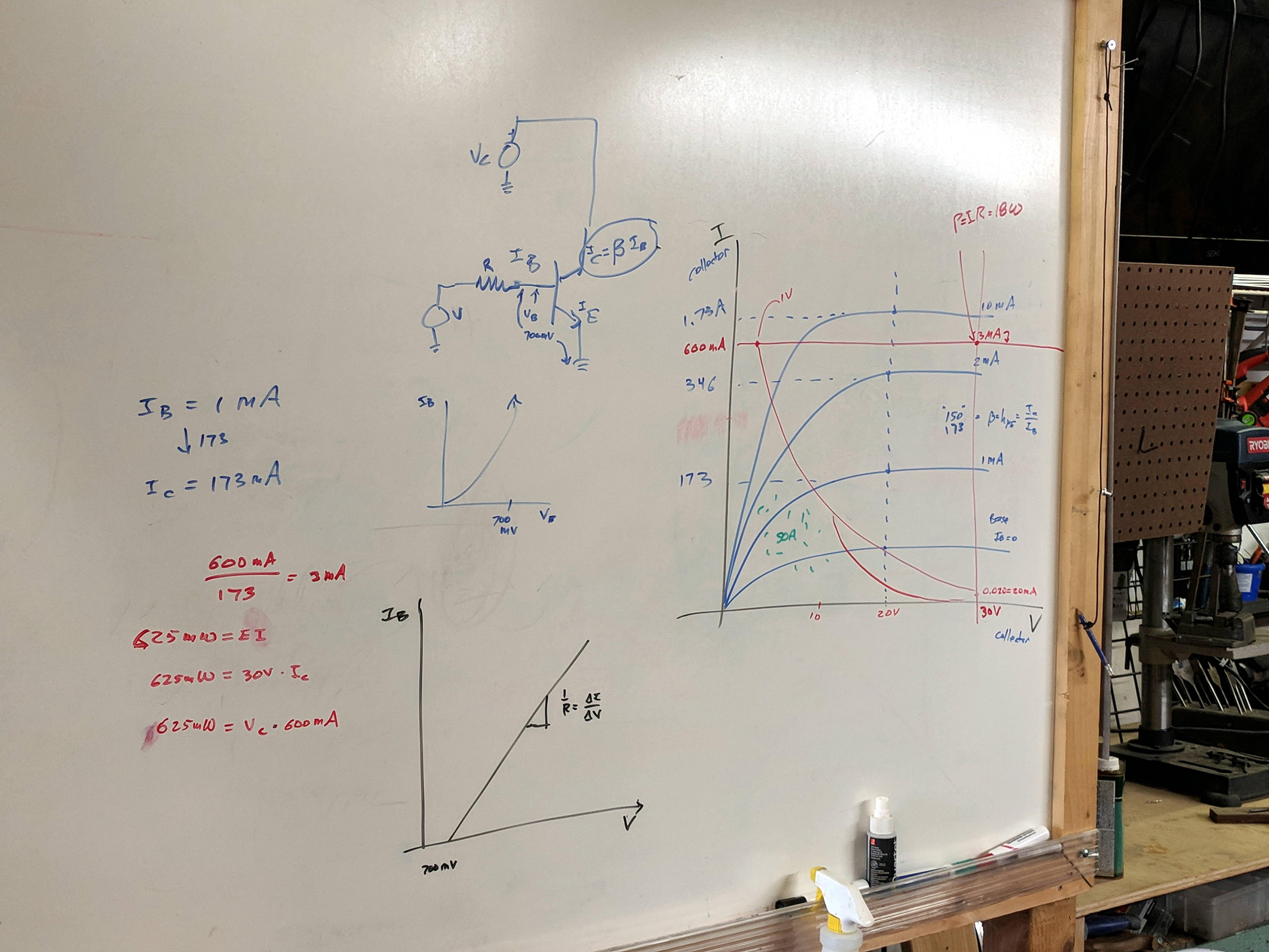
Whiteboards from the SqWr Electronics Session 5, covering transistors as switches …
Reviewing I vs V plots, starting with a resistor and then a transistor as a current amplifier:
SqWr Electronics 5 – whiteboard 1
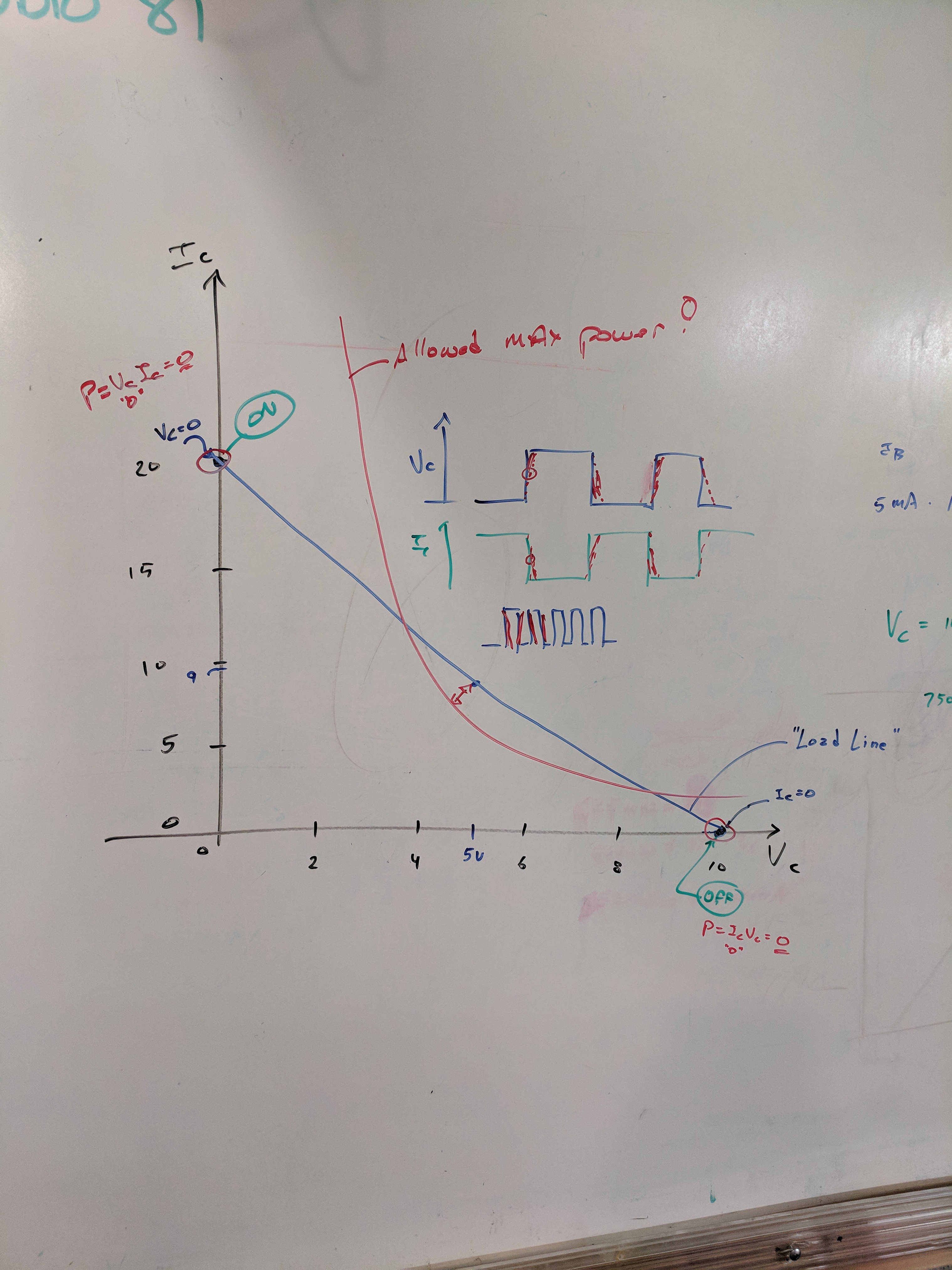
Reminder of why you can’t run a transistor at its maximum voltage and current at the same time:
SqWr Electronics 5 – whiteboard 2
A resistor load line, with power calculation at the switch on and off coordinates:
SqWr Electronics 5 – whiteboard 3
Detail of the power calculations, along with a diagram of the current and voltage when you actually switch the poor thing:
SqWr Electronics 5 – whiteboard 3 detail
Oversimplification: most of the power happens in the middle, but as long as the switching frequency isn’t too high, it’s all good.
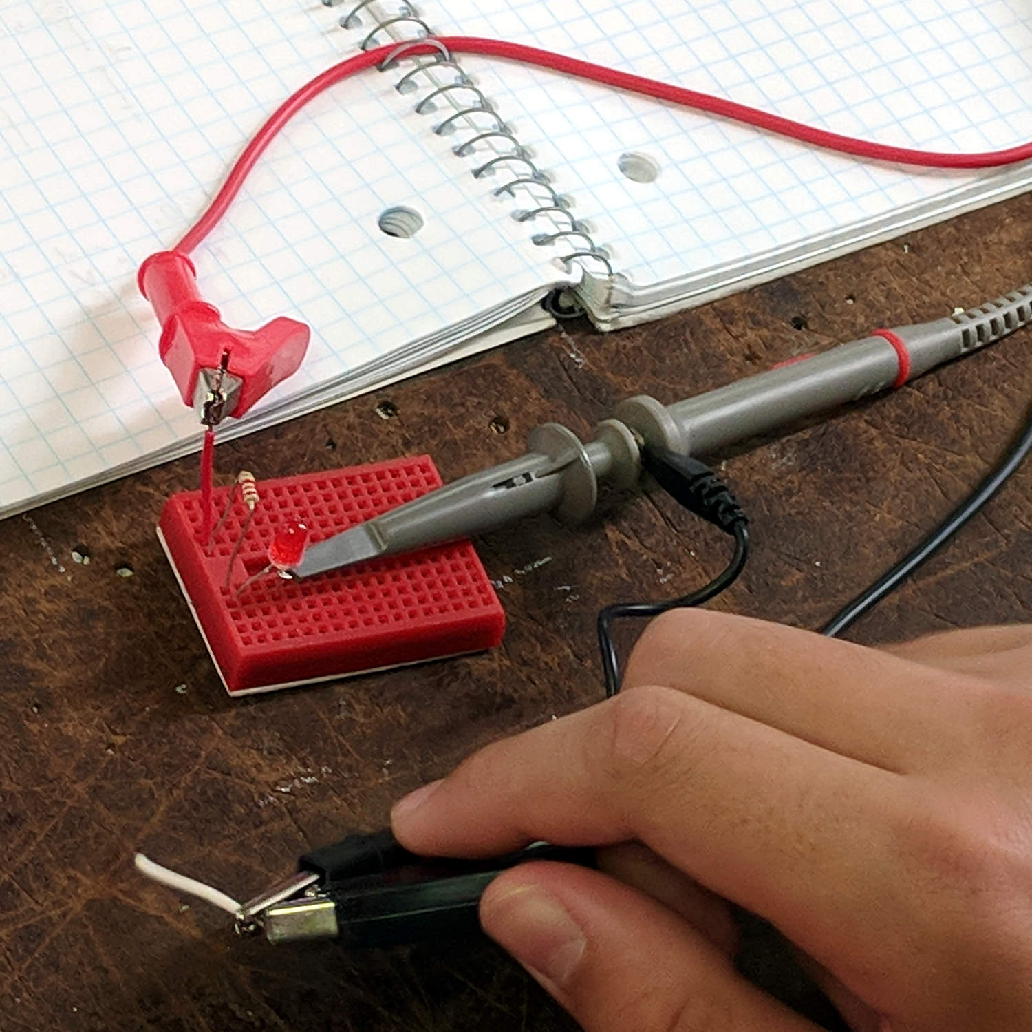
Schematic of the simplest possible switched LED circuit, along with a familiar mechanical switch equivalent:
SqWr Electronics 5 – whiteboard 4
We started with the “mechanical switch” to verify the connections:
SqWr Session 5 – Switched LED breadboard
Building the circuitry wasn’t too difficult, but covering the function generator and oscilloscope hookup took far more time than I expected.
My old analog Tek 2215 scope was a crowd-pleaser; there’s something visceral about watching a live CRT display you just don’t get from the annotated display on an LCD panel.
I’d planned to introduce capacitors, but just the cap show-n-tell went well into overtime. We’ll get into those in Session 6, plus exploring RC circuitry with function generators and oscilloscopes.