A House Finch suffering from Finch Eye Disease prompted me to sterilize our feeder, which meant providing a temporary feeder to keep the birds flying. Having an abundance of lids from six gallon plastic cans / buckets, this made sense:

Which required an adapter betwixt pole and lid:

Which requires a bit of solid modeling:
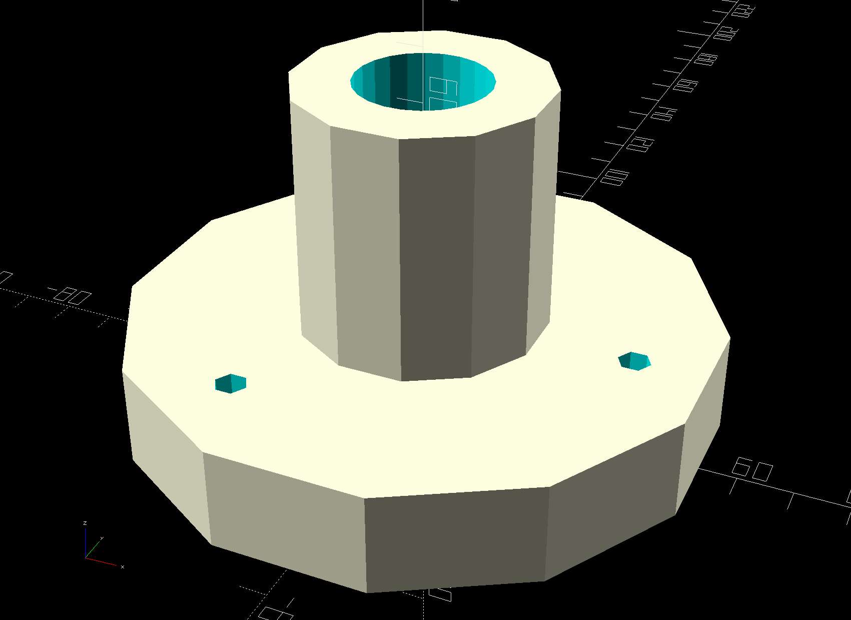
The lids have a central boss, presumably for stiffening, so the model includes a suitable recess:

As usual, automatically generated support fills the entire recess, so I designed a minimal support structure into the model and cracked it out with very little effort:

The tangle off to the right comes from a bridge layer with a hole in the middle, which never works well even with support:

Didn’t bother the birds in the least, though, so it’s all good.
I loves me my 3D printer …
The OpenSCAD source code as a GitHub Gist:
| // Adapter from steel pole to 5 gallon plastic can lid | |
| // Turns the lid into a improvised platform feeder | |
| // Ed Nisley – KE4ZNU – 2018-11 | |
| Layout = "Build"; // Show Build | |
| ThreadThick = 0.25; | |
| ThreadWidth = 0.40; | |
| HoleWindage = 0.2; | |
| function IntegerMultiple(Size,Unit) = Unit * ceil(Size / Unit); | |
| Protrusion = 0.1; // make holes end cleanly | |
| // Sizes | |
| ID = 0; | |
| OD = 1; | |
| LENGTH = 2; | |
| Wall = 10; // minimum thickness or width for anything | |
| Boss = [15,50,9]; // central boss on lie | |
| Flange = [50,110,Boss[LENGTH] + Wall]; | |
| echo(Boss); | |
| echo(Flange); | |
| Pole = [(23.5 + 4*HoleWindage),26,45]; // small end of steel pole | |
| Screw = [5.0,8.0,25.0]; // 5 mm or 10-32 | |
| ScrewOC = 80; // lid mounting screws | |
| NumScrews = 3; | |
| NumSides = NumScrews*2*4; | |
| $fn = NumSides; | |
| //———————- | |
| // Useful routines | |
| module PolyCyl(Dia,Height,ForceSides=0) { // based on nophead's polyholes | |
| Sides = (ForceSides != 0) ? ForceSides : (ceil(Dia) + 2); | |
| FixDia = Dia / cos(180/Sides); | |
| cylinder(r=(FixDia + HoleWindage)/2,h=Height,$fn=Sides); | |
| } | |
| //———————- | |
| // Build it | |
| module Bracket() { | |
| difference() { | |
| union() { | |
| rotate(180/(NumSides/2)) { | |
| cylinder(d=Flange[OD],h=Flange[LENGTH],$fn=NumSides/2); // fewer sides is OK | |
| cylinder(d=Pole[OD] + 2*Wall,h=Pole[LENGTH] + Flange[LENGTH],$fn=NumSides/2); | |
| } | |
| } | |
| translate([0,0,-Protrusion]) | |
| rotate(180/NumSides) | |
| cylinder(d=Boss[OD],h=Boss[LENGTH] + Protrusion,$fn=NumSides); | |
| translate([0,0,-Protrusion]) | |
| rotate(180/NumSides) | |
| cylinder(d=Pole[ID],h=2*(Pole[LENGTH] + Flange[LENGTH]),$fn=NumSides); | |
| for (i=[0:NumScrews-1]) | |
| rotate(i*(360/NumScrews)) | |
| translate([ScrewOC/2,0,-Protrusion]) | |
| PolyCyl(Screw[ID],2*Flange[LENGTH],6); | |
| } | |
| } | |
| module Support() { | |
| NumRibs = NumSides/2; | |
| Rib = [0.95*(Boss[OD] – Pole[ID])/2,2*ThreadWidth,Boss[LENGTH] – ThreadThick]; | |
| color("Yellow") { | |
| for (i=[0:NumRibs-1]) { | |
| a = i*360/NumRibs; | |
| rotate(a) | |
| translate([Pole[ID]/2 + Rib.x/2,0,Rib.z/2]) | |
| cube(Rib,center=true); | |
| } | |
| rotate(180/NumSides) | |
| difference() { | |
| cylinder(d=Pole[ID] + 10*ThreadWidth,h=1*ThreadThick,$fn=NumSides); | |
| translate([0,0,-Protrusion]) | |
| cylinder(d=Pole[ID],h=Rib.z + 2*Protrusion,$fn=NumSides); | |
| } | |
| } | |
| } | |
| if (Layout == "Show") | |
| Bracket(); | |
| if (Layout == "Build") { | |
| Bracket(); | |
| Support(); | |
| } |