Ed Nisley's Blog: Shop notes, electronics, firmware, machinery, 3D printing, laser cuttery, and curiosities. Contents: 100% human thinking, 0% AI slop.
Category: Science
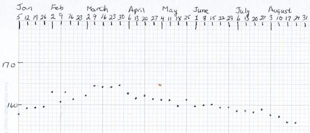
If you measure something often enough, it becomes science
The Butterfly Bush in front of the house attracts all kinds of insects, including Monarch Butterflies (shown here on the Goldenrod planted in the garden):
Monarch on Goldenrod – left
This year, the bush also attracted a Praying Mantis:
I started low-key upper-body strength training in June with encouraging results: my biceps no longer require exotic instrumentation for detection and my abs may soon transition from “throw pillow” to “two-pack”.
This is, however, the season of bounteous garden harvests, including delicious corn-on-the-cob and summer squash …
The X axis driver is an unmodified DRV8825 PCB operating in default mixed-decay mode. The Y axis DRV8825 has its DECAY pin pulled high, thereby putting it in fast decay mode.
The scope timebase varies to match the programmed feed rate. Because the X and Y axes move simultaneously, each axis moves at 1/√2 the programmed speed:
G1 X10 Y10 F100 → 71 mm/min on X and Y
The motor generates minimal back EMF at slow speeds, so the winding sees nearly the full supply voltage. As described in the previous post, the basic problem arises when the current rises too fast during each PWM cycle:
V = L di/dt
di/dt = 24 V / 3 mH = 8 kA/s
The first 1:32 microstep away from 0 calls for 5% of max current = 50 mA at a 1 A peak. The DRV8825 datasheet says the PWM typically runs at 30 kHz = 33 µs/cycle, during which the current will change by 270 mA:
267 mA = 8 kA/s × 33.3 µs
Notice how the current slams to a nearly constant, much-too-high value just after the first microstep. The incorrect current level decreases with lower supply voltage, because the rate-of-change decreases and the commanded current level reaches the actual (incorrect) current sooner.
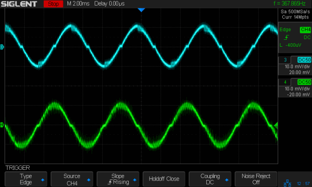
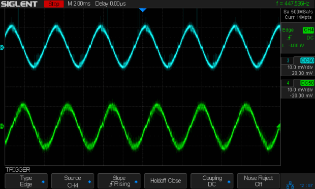
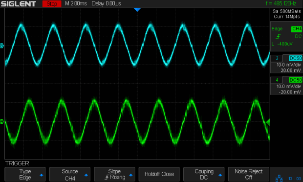
Varying the motor voltage at a constant 10 mm/min:
3018 XY – Mixed Fast – 24V – 10mm-min 1A-div
3018 XY – Mixed Fast – 20V – 10mm-min 1A-div
3018 XY – Mixed Fast – 15V – 10mm-min 1A-div
3018 XY – Mixed Fast – 12V – 10mm-min 1A-div
3018 XY – Mixed Fast – 10V – 10mm-min 1A-div
Note that reducing the supply voltage doesn’t change the motor winding current, because the DRV8825 controls the current during each microstep, at least to the best of its ability.
Also note that the current overshoots the target for those microsteps, even when the motor is stopped, because there’s no back EMF, so the power dissipation is too high even at rest.
Enough back EMF appears at 100 mm/min to begin tamping down the current overshoot at 24 V:
3018 XY – Mixed Fast – 24V – 100mm-min 1A-div
The current waveform looks good at 12 V:
3018 XY – Mixed Fast – 12V – 100mm-min 1A-div
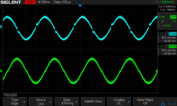
The back EMF at 1000 mm/min nearly eliminates the overshoot at 24 V, with fast decay in the Y axis causing some PWM ripple:
3018 XY – Mixed Fast – 24V – 1000mm-min 1A-div
Both decay modes look good at 12 V:
3018 XY – Mixed Fast – 12V – 1000mm-min 1A-div
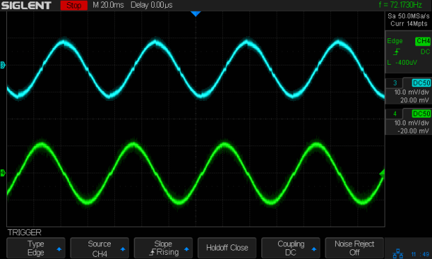
At 1500 mm/min, the highest reasonable speed for the thing, and a 24 V supply, both waveforms still look good:
3018 XY – Mixed Fast – 24V – 1500mm-min 1A-div
However, the back EMF is now high enough to buck the 12 V supply, preventing the current from decreasing fast enough in mixed decay mode (top trace):
3018 XY – Mixed Fast – 12V – 1500mm-min 1A-div
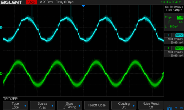
Tweaking the GRBL config to allow 2000 mm/min feeds shows the waveforms starting to become triangular, even at 24 V:
3018 XY – Mixed Fast – 24V – 2000mm-min 1A-div
And a 12 V supply opposed by the back EMF simply can’t change the current fast enough to keep up with the DRV8825 microstep current levels:
3018 XY – Mixed Fast – 12V – 2000mm-min 1A-div
Bottom line: a +12 V motor supply and DRV8825 drivers modified to run in fast decay mode look like the best setup for the 3018-Pro: good current control at low speeds with enough moxie to handle higher speeds.
I should hack the DRV8825 boards into 1:8 microstep mode to reduce the IRQ rate by a factor of four, then see what happens to the back EMF at absurd speeds.
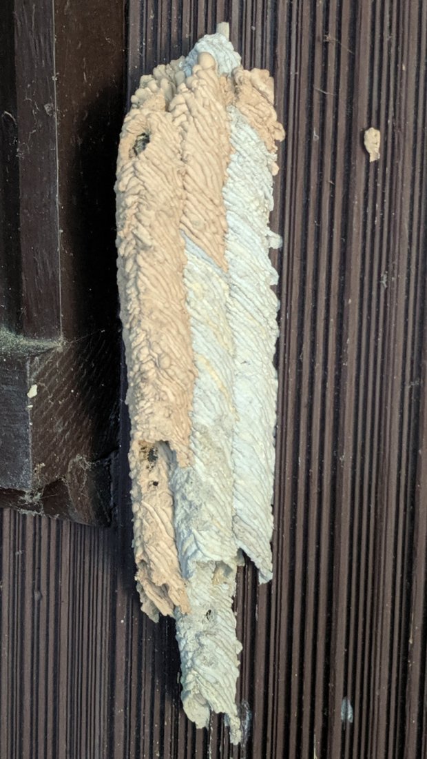
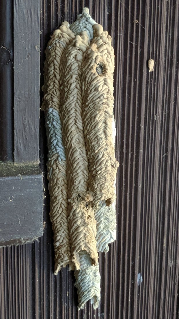
Their offspring began emerging in early July, with our first picture on 3 July. I’ll leave the image file dates in place so you can reach your own conclusions:
IMG_20190703_184657 – Organ Pipe Mud Dauber Nest – right
We think a titmouse (a known predator) pecked some holes, including the upper hole on the middle tube, as they seemed to expose solid (and presumably inedible) chitin from the outside:
IMG_20190703_184647 – Organ Pipe Mud Dauber Nest – left
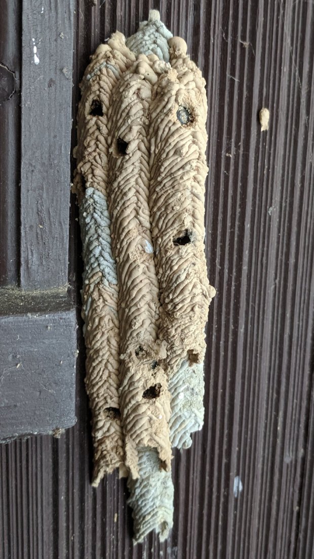
More holes appeared in a few days:
IMG_20190709_172632 – Organ Pipe Mud Dauber Nest – right
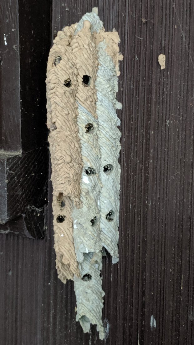
The irregular spacing along each tube suggests they don’t emerge in the reverse order of installation:
IMG_20190709_172623 – Organ Pipe Mud Dauber Nest – left
Three days later:
IMG_20190712_181634 – Organ Pipe Mud Dauber Nest – right
IMG_20190712_181625 – Organ Pipe Mud Dauber Nest – left
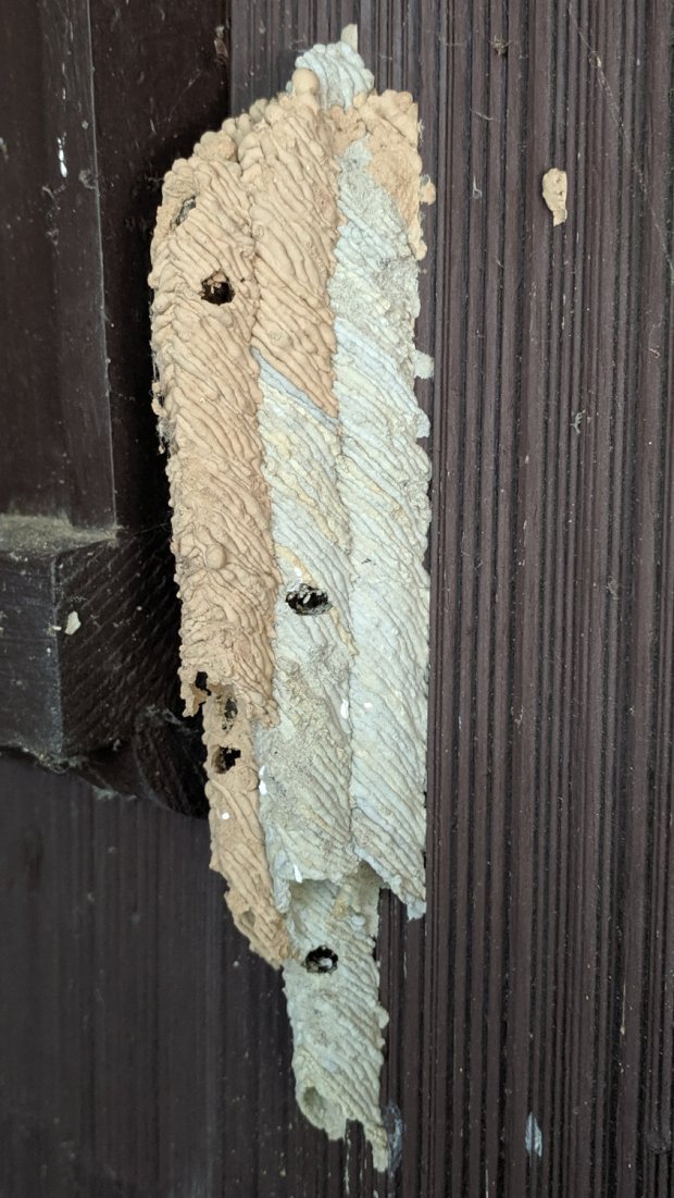
Two weeks after the first holes appeared:
IMG_20190717_172908 – Organ Pipe Mud Dauber Nest – right
IMG_20190717_172922 – Organ Pipe Mud Dauber Nest – left
No more holes have appeared since then, so it seems one young wasp emerges every few days.
This nest produced about a dozen wasps, with perhaps as many launch failures. We’ll (try to) remove it and examine the contents in a few months.
We expect they’ll start building nests all over the house in another month …
Update: Fortunately for us, no nests appeared before the first freeze, so the wasps are holed up elsewhere for the winter.
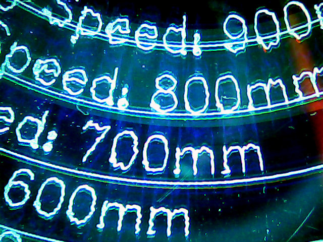
The MPCNC isn’t the most stable of CNC machine tools, given its large masses and 3D printed structure. My early plotting pen tests suggested speeds around 250 mm/min were appropriate:
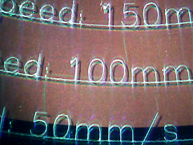
Those “mm/s” labels are typos; they should read “mm/min”. Plotting at -1.0 mm on scrap CDs and DVDs produces a downforce around 200 g.
Eyeballometrically, 100 mm/min seems fine, but 50 mm/min (I’d likely use 60 for a nice round 1 mm/s) eliminates all the shakes.
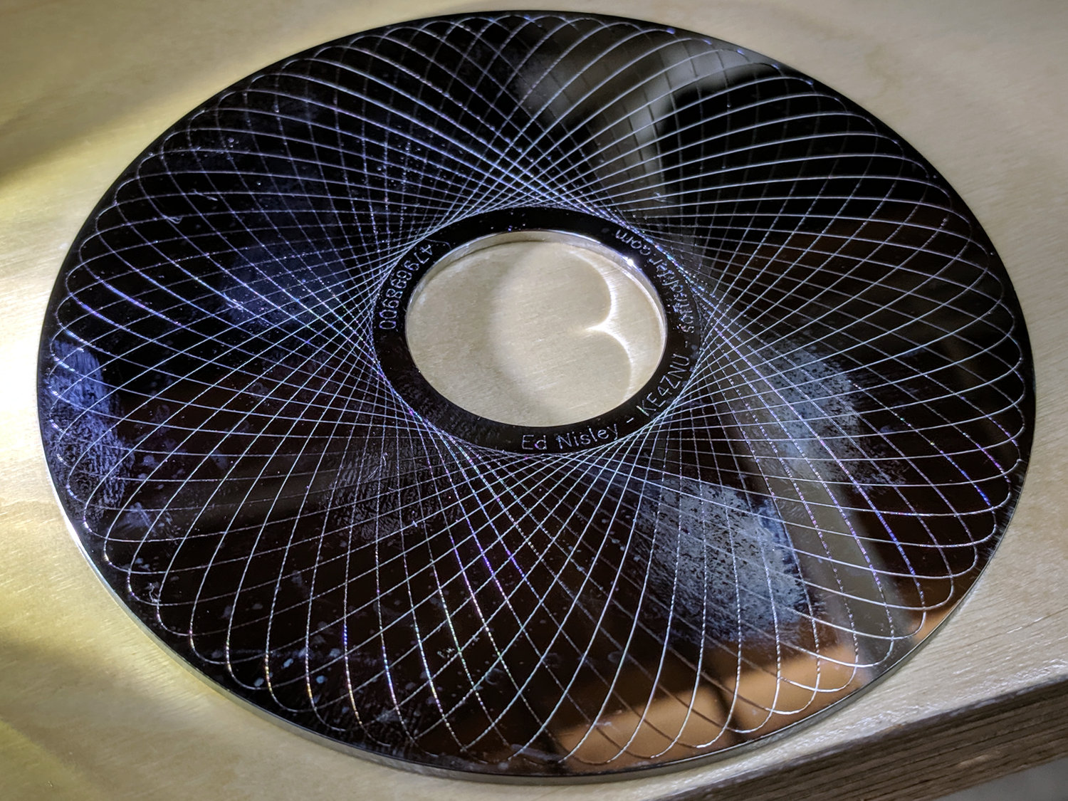
Smooth curves, like Guillloché patterns, can run much faster, because they don’t have abrupt direction changes. This 3-½ inch hard drive platter has text engraved at 100 mm/min and the pattern at 600 mm/min, both at -3.0 mm for 300 g of downforce:
MPCNC Engraving – Guilloche drive platter test
A closer look at the text:
MPCNC Engraving – hard drive platter – detail A
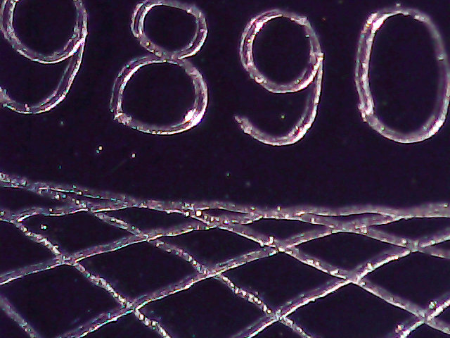
And some digits:
MPCNC Engraving – hard drive platter – detail B
When I want to brand an engraved CD, this will suffice:
MPCNC Engraving – CD attribution text
All in all, the MPCNC engraves much better than I expected!
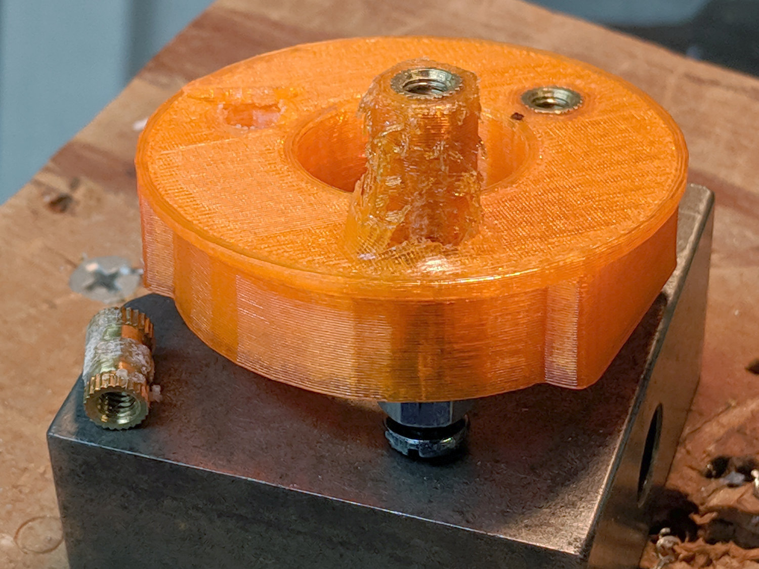
The retina-burn orange ring is printed in PETG with my usual slicer settings: three perimeter threads, three top and bottom layers, and 15% 3D honeycomb infill. That combination is strong enough and stiff enough for essentially everything I do around here.
The insert on the left came out of its hole carrying its layer of epoxy: the epoxy-to-hole bond failed first. Despite that, punching it out required enough force to convince me it wasn’t going anywhere on its own.
The column of plastic around the insert standing up from the top fits into the central hole (hidden in the picture) in the bench block. Basically, the edge of the hole applied enough shear force to the plastic to break the infill before the epoxy tore free, with me applying enough grunt to the drill press quill handle to suggest I should get a real arbor press if I’m going to keep doing this.
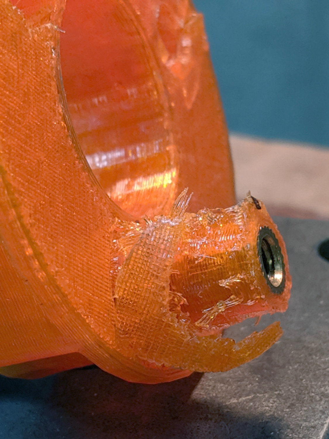
The third insert maintained a similar grip, as seen from the left:
Brass Insert Retention test – C left
And the right:
Brass Insert Retention test – C right
The perimeter threads around the hole tore away from the infill, with the surface shearing as the plastic column punched through.
Bottom line: a dab of epoxy anchors an insert far better than the 3D printed structure around it can support!